

LG LSC27950SW, LSC27950SB, LSC27950ST, LSC27960ST Service Manual

CAUTION
PLEASE READ CAREFULLY THE SAFETY PRECAUTIONS OF THIS MANUAL
BEFORE CHECKING OR OPERATING THE REFRIGERATOR.
REFRIGERATOR
SERVICE MANUAL
MODEL : LSC27950SW/ LSC27950SB
LSC27950ST/ LSC27960ST
COLOR : SUPER WHITE
WESTERN BLACK
STAINLESS
http://aic.lgservice.com

CONTENTS
WARNINGS AND PRECAUTIONS FOR SAFETY ................................................................................................................ 3
SPECIFICATIONS................................................................................................................................................................... 4
PARTS IDENTIFICATION ........................................................................................................................................................6
HOW TO INSTALL THE REFRIGERATOR ............................................................................................................................ 8
HOW TO ADJUST DOOR HEIGHT...................................................................................................................................... 8
FILTER ................................................................................................................................................................................. 9
HOW TO CONTROL THE ICEMAKER WATER SUPPLY.................................................................................................. 10
MICOM FUNCTION............................................................................................................................................................... 11
EXPLANATION OF MICOM CIRCUIT.................................................................................................................................. 26
EXPLANATION OF PWB CIRCUIT .....................................................................................................................................26
PWB PARTS DIAGRAM AND LIST .....................................................................................................................................45
PWB CIRCUIT DIAGRAM ...................................................................................................................................................50
ICEMAKER AND DISPENSER WORKING PRINCIPLES AND REPAIR ............................................................................52
WORKING PRINCIPLES.................................................................................................................................................... 52
FUNCTION OF ICEMAKER ............................................................................................................................................... 53
CIRCUIT................................................................................................................................................................................ 55
TROUBLE DIAGNOSIS........................................................................................................................................................ 57
TROUBLESHOOTING ....................................................................................................................................................... 57
FAULTS .............................................................................................................................................................................. 67
COOLING CYCLE HEAVY REPAIR ................................................................................................................................... 84
HOW TO DEAL WITH CLAIMS.......................................................................................................................................... 91
HOW TO DISASSEMBLE AND ASSEMBLE....................................................................................................................... 96
DOOR................................................................................................................................................................................. 96
HANDLE ............................................................................................................................................................................. 97
FAN SHROUD GRILLE ...................................................................................................................................................... 97
WATER VALVE DISASSEMBLY METHOD .........................................................................................................................98
FAN and FAN MOTOR DISASSEMBLY METHOD..............................................................................................................98
DISPENSER....................................................................................................................................................................... 99
EXPLODED VIEW .............................................................................................................................................................. 101
REPLACEMENT PARTS LIST............................................................................................................................................ 113
- 2 -

WARNINGS AND PRECAUTIONS FOR SAFETY
Please observe the following safety precautions to use the
refrigerator safely and correctly and to prevent accident or
injury when servicing.
1. Be careful of an electric shock. Disconnect the power
cord from wall outlet and wait for more than three
minutes before replacing PWB parts. Shut off the power
whenever replacing and repairing electric components.
2. When connecting the power cord, please wait for more
than five minutes after the power cord was disconnected
from the wall outlet.
3. Check if the power cord is pinched between the
refrigerator and the wall. If the plug or cord is damaged,
it could cause a fire or an electric shock
4. If the wall outlet is overloaded, it may cause a fire. Use a
dedicated circuit for the refrigerator.
5. Make sure the outlet is properly grounded.
Particularly in a wet or damp area.
6. Use standard electrical components.
7.Remove dust and foreign materials from the housing and
connecting parts.
8. Do not fray, damage, run over, kink, bend, pull out, or
twist the power cord.
9. Check for evidence of moisture intrusion in the
electrical components. Replace the parts or mask with
insulation tape if moisture intrusion was confirmed.
10. Do not insert fingers or tools into the icemaker. The
geared motor drive could cause an injury or damage to
tools or the icemaker .
11. Do not suggest that customers repair their refrigerator
themselves. This work requires special tools and
knowledge. Non-professionals could cause fire, injury,
or damage to the product.
12. Do not store flammable materials such as ether,
benzene, alcohol, chemicals, or gas.
13. Do not put anything on top of the refrigerator,
especially something containing water, like a vase.
14. Do not put glass bottles with full of water into the
freezer. The contents will freeze and break the glass
bottles.
15. When you scrap or discard the refrigerator, remove the
doors and dispose of it where children are not likely to
play in or around it.
16. This is a consumer grade product. It is not intended for
precise storage of medication.
- 3 -
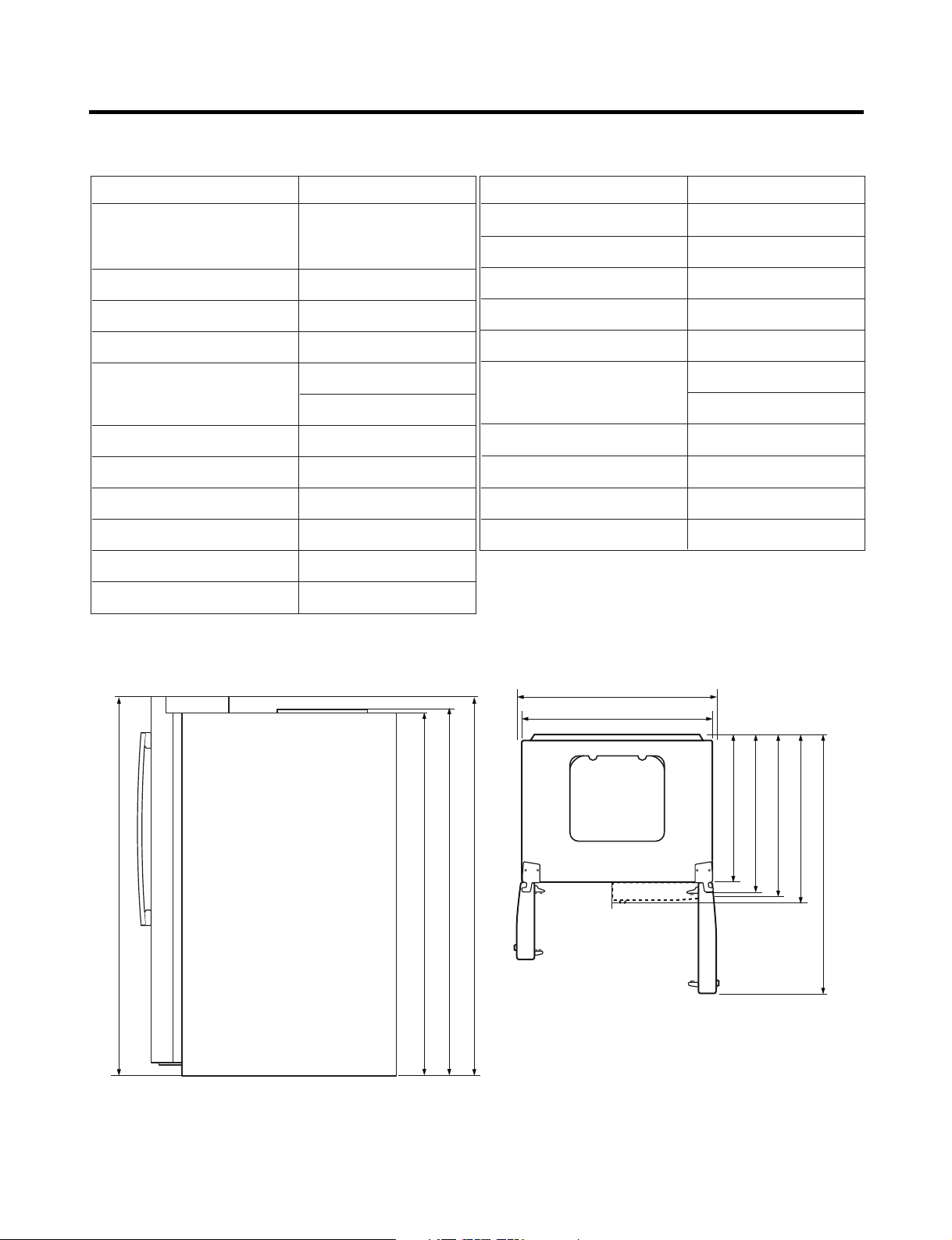
SPECIFICATIONS
724 mm (28
1
/
2
in.)
1004 mm (391/2 in.)
908 mm (39
11
/16 in.)
779 mm (30
5
/
8
in.)
829 mm (32
5
/
8
in.)
897 mm (35
5
/
16
in.)
1261 mm (49
5
/
8
in.)
1741.5 mm (68
1
/
2
in.)
1746.5 mm (68
3
/
4
in.)
1771 mm (69
11
/
16
in.)
1771 mm (69
11
/
16
in.)
1. Ref No. : GR-L277SV(S)VA (LSC27950SW, LSC27950SB, LSC27950ST)
ITEMS SPECIFICATIONS
DIMENSIONS 908 X 896 X 1771 mm
W
X D X
H (35
NET WEIGHT 149 kg (328.5 lbs.)
COOLING SYSTEM Fan Cooling
TEMPERATURE CONTROL Micom Control
DEFROSTING SYSTEM Full Automatic
INSULATION Cyclo-Pentane
COMPRESSOR PTC Starting Type
EVAPORATOR Fin Tube Type
CONDENSER Wire Condenser
REFRIGERANT R134a (185g) (6
LUBRICATING OIL FREOL @10G (320 cc)
11
/16X355/16X6911/16 in.)
Heater Defrost
1
/2 oz.)
ITEMS SPECIFICATIONS
DRIER MOLECULAR SIEVE XH-7
CAPILLARY TUBE ID Ø0.83
FIRST DEFROST 4 - 5 Hours
DEFROST CYCLE 13 - 15 Hours
DEFROSTING DEVICE Heater, Sheath
ANTI-SWEAT HEATER Dispenser Duct Door Heater
Dispenser Heater
ANTI-FREEZING HEATER Damper Heater
FREEZER LAMP 40W (1 EA)
REFRIGERATOR LAMP 40W (4 EA)
DISPENSER LAMP 15W (1 EA)
Front View Top View
- 4 -
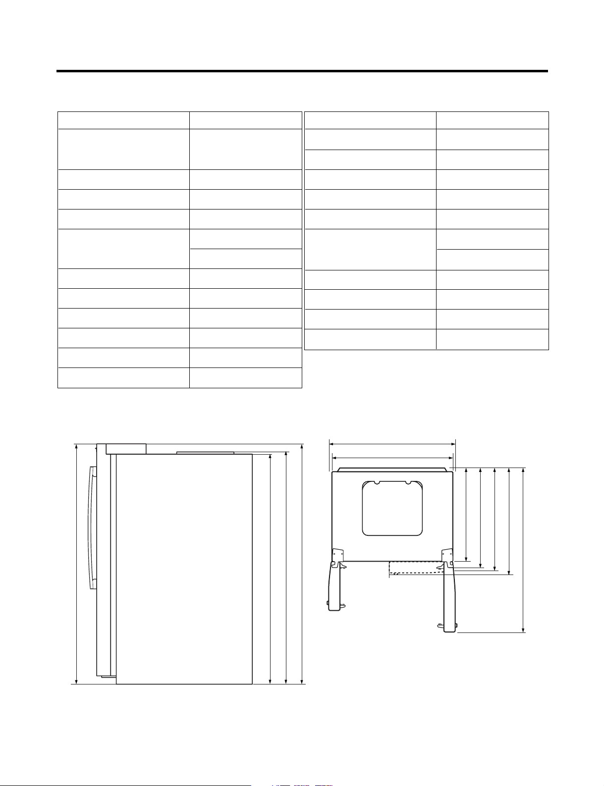
SPECIFICATIONS
2. Ref No. : GR-L277SSWA (LSC27960ST)
ITEMS SPECIFICATIONS
DIMENSIONS 908 X 896 X 1771 mm
W
X D X
H (35
NET WEIGHT 149 kg (328.5 lbs.)
COOLING SYSTEM Fan Cooling
TEMPERATURE CONTROL Micom Control
DEFROSTING SYSTEM Full Automatic
INSULATION Cyclo-Pentane
COMPRESSOR PTC Starting Type
EVAPORATOR Fin Tube Type
CONDENSER Wire Condenser
REFRIGERANT R134a (185g) (6
LUBRICATING OIL FREOL @10G (320 cc)
11
/16X355/16X6911/16 in.)
Heater Defrost
1
/2 oz.)
ITEMS SPECIFICATIONS
DRIER MOLECULAR SIEVE XH-7
CAPILLARY TUBE ID Ø0.83
FIRST DEFROST 4 - 5 Hours
DEFROST CYCLE 13 - 15 Hours
DEFROSTING DEVICE Heater, Sheath
ANTI-SWEAT HEATER Dispenser Duct Door Heater
Dispenser Heater
ANTI-FREEZING HEATER Damper Heater
FREEZER LAMP 40W (1 EA)
REFRIGERATOR LAMP 40W (4 EA)
DISPENSER LAMP 15W (1 EA)
in.)
16
/
11
1771 mm (69
1004 mm (391/2 in.)
11
908 mm (39
in.)
in.)
2
/
1
1741.5 mm (68
Front View Top View
in.)
4
/
16
3
/
11
1771 mm (69
1746.5 mm (68
/16 in.)
in.)
in.)
in.)
2
8
8
/
/
1
/
5
5
724 mm (28
779 mm (30
829 mm (32
in.)
in.)
8
/
16
5
/
5
897 mm (35
1261 mm (49
- 5 -
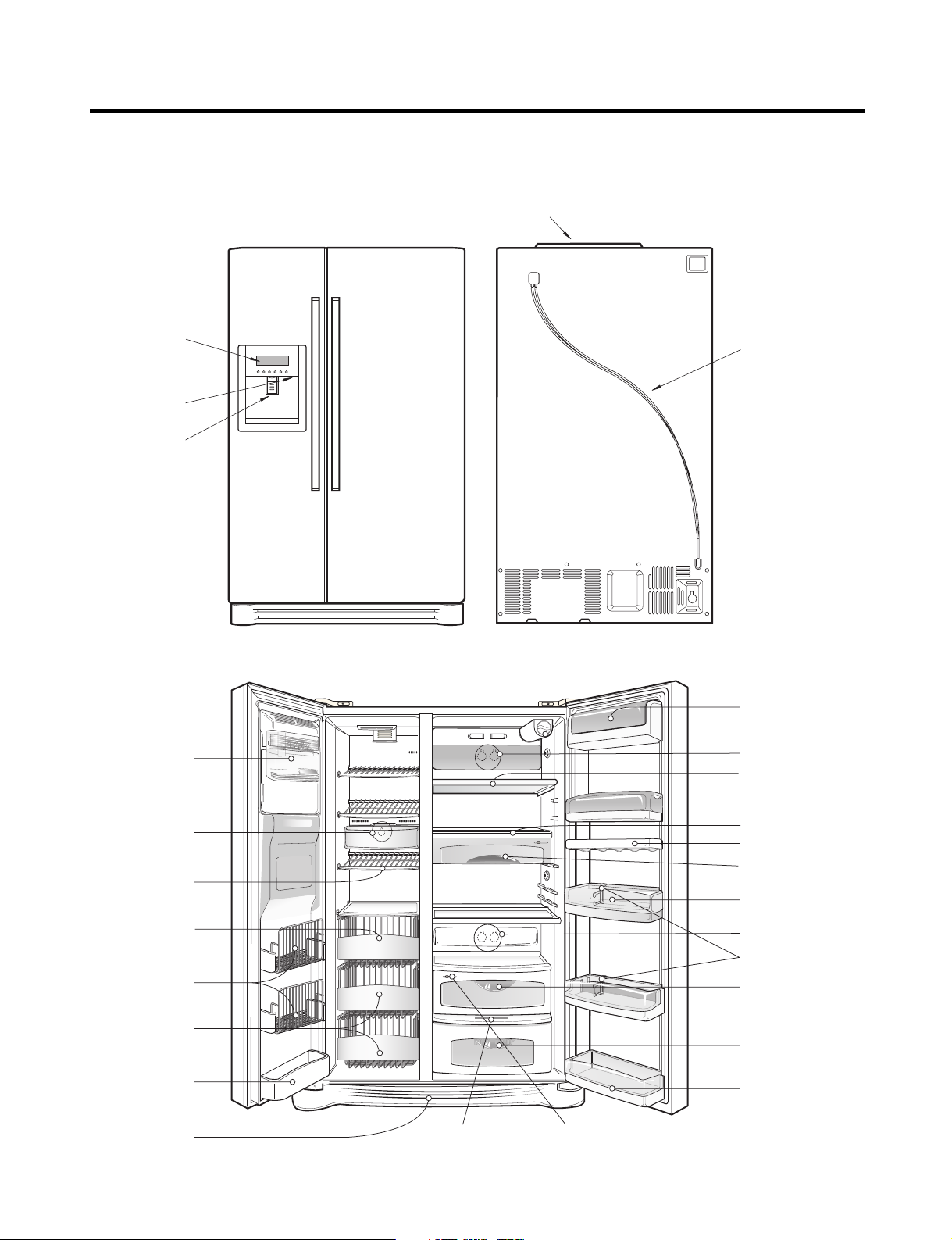
PARTS IDENTIFICATION
1. Ref No. : GR-L277SV(S)VA (LSC27950SW, LSC27950SB, LSC27950ST)
PWB Cover
Frame Display
Dispenser Lamp
Ice & Water
Dispenser Button
Automatic
Icemaker
Freezer
Compartment
Water Tubes
Refrigerator
Compartment
Dairy Product Corner
Water Filter
Lamp
Shelf
Lamp
Shelf
Drawer
Door Rack
Drawer
Door Rack
Lower Cover OptiFresh Display Humidity Switch
- 6 -
Shelf
Can Server
Snack Drawer
Door Rack
Lamp
Bottle Guide
Vegetable Drawer
OptiFresh
Door Rack

PARTS IDENTIFICATION
2. Ref No. : GR-L277SSWA (LSC27960ST)
PWB Cover
Frame Display
Dispenser Lamp
Ice & Water
Dispenser Button
Automatic
Icemaker
Freezer
Compartment
Water Tubes
Refrigerator
Compartment
Dairy Product Corner
Water Filter
Lamp
Shelf
Lamp
Shelf
Drawer
Door Rack
Drawer
Door Rack
Lower Cover OptiFresh Display Humidity Switch
- 7 -
Shelf
Can Server
Snack Drawer
Door Rack
Lamp
Bottle Guide
Vegetable Drawer
OptiFresh
Door Rack
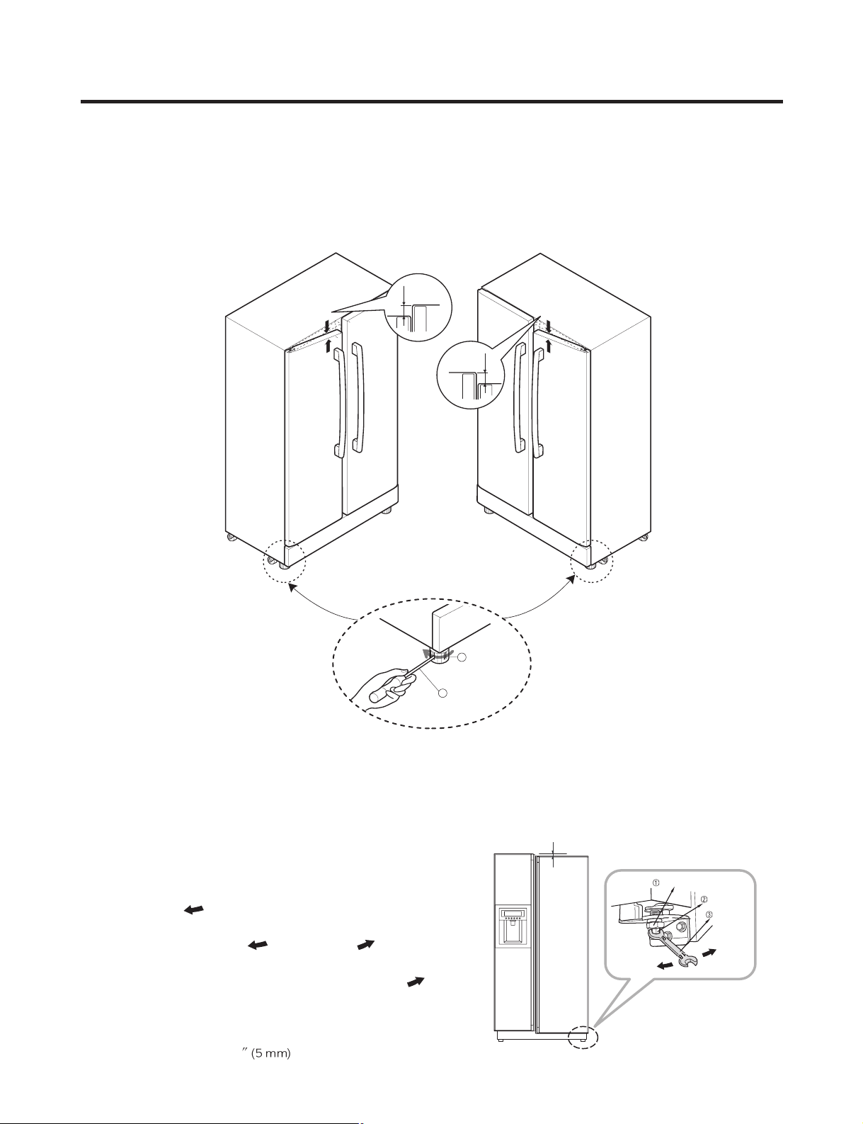
HOW TO INSTALL REFRIGERATOR
Adjusting
Screw
Driver
Height
Difference
Height
Difference
Height
Difference
Height
Difference
1
2
Keeper nut
Up
Down
Adjustment
hinge pin
Tool for
adjustment
1. How to Adjust Door Height of Refrigerator
■ Make the refrigerator level first. (If the refrigerator is not installed on a flat floor, the height of freezer and refrigerator
door may not be the same.)
1) If the freezer door is lower than the refrigerator
door:
2) If the freezer door is higher than the refrigerator
door:
Insert a driver into the groove of the adjusting
screw and turn in the direction of the arrow (clockwise)
until the refrigerator is level.
3) When the refrigerator door is lower than the freezer door
Adjust the level when the refrigerator door is lower than the
freezer door during
the use of the refrigerator.
(1) Using the wide side of the tool for adjustment , turn the
keeper nut ( ) clockwise to loosen the keeper nut.
(2) Using the narrow side of the tool for adjustment, turn the
adjustment hinge pin ( ) clockwise or ( )
counterclockwise to level the refrigerator and freezer door.
(3) After setting the level of the door, turn the keeper nut ( )
counterclockwise to tighten.
Caution : Do not force too hard to level the height. The hinge
pin can be pulled out (Adjustable range of height:
Maximum of 2/10
).
- 8 -
Insert a driver into the groove if the adjusting screw
and turn in the direction of the arrow (clockwise) until the
refrigerator is level.

HOW TO INSTALL REFRIGERATOR
2. Filter
Replace the filter when the indicator light comes on or the
performance of the icemker or water dispenser decreases
noticeably.
After changing the water filter cartridge, reset the water
filter status display and indicator light by pressing and
holding the FILTER Button for 3 seconds. (page 13)
1) Remove the old cartridge.
Twist the knob of the cartridge counterclockwise.
2) Replace with a new cartridge.
Take the new cartridge out of its packaging and remove
protective cover from the o-rings.
With cartridge knob in the vertical position, push the new
filter cartridge into the cover until it stops.
If you can’t turn the filter from side to side, it isn’t fully
inserted. Push it in firmly and twist it into place. You will
hear the snap when it clicks into place.
Using the handle, twist the cartridge clockwise about 1/4
turn.
When the cartridge is removed, you will feel it click .
Pull out the cartridge.
NOTE: There will be some water (25cc) in the filter
cartridge. Some spilling may occur. Catch it in a
bowl or towel.
3) Flush the Water System After Replacing Filter
Dispense water through the water dispenser for 3
minutes to purge the system.
There may be a little air in the line, causing noise or
hissing. Run the water at the dispenser until the hissing
stops to purge the air from the system.
NOTE: - To purchase replacement water filter cartridges,
visit your local appliance dealer or part distributor.
- You can also visit our website :
www.lgappliances.com or call 1-877-714-7481.
LG MDL PART NO MAKER
GR-L277SV(S)VA
LSC27950 SW/SB/ST
GR-L277SSWA
LSC27960ST
5231JA2006A CUNO
- 9 -
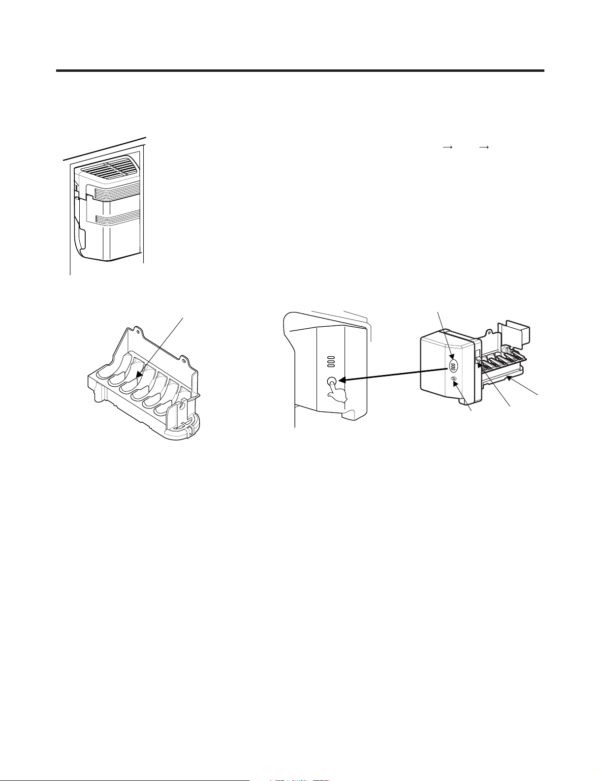
HOW TO INSTALL REFRIGERATOR
Water Amount
Indicator Light
Power
Switch
Water Amount
Selection Button
Feeler
Arm
Check water level
3. How to Control the Amount of Water Supplied to Icemaker.
3-1. Confirm the amount of water supplied to the icemaker.
1) Confirm the amount of water supplied to the icemaker
(1) Press the button (Figure 1) to selsct the level of water (Optimum level
2) Icemaker Operation Test (Test mode)
(1) Press the button (Figure 1) for more than 3 seconds and It will start the Test mode.
(2) Test the operation of the operating part of the icemaker.
(3) If there is no problem with the operation, water is supplied through the water tube (up to the
selected lebel of water).
(4) The test mode is completed after the water is supplied.
Note : When using the test mode more than twice consecutively, water can overflow.
When the water overflows, wipe the ice storage bin.
Large Small.)
* It is acceptable if the adjusted level of water is a bit smaller than optimum level.
Figure 1.
- 10 -
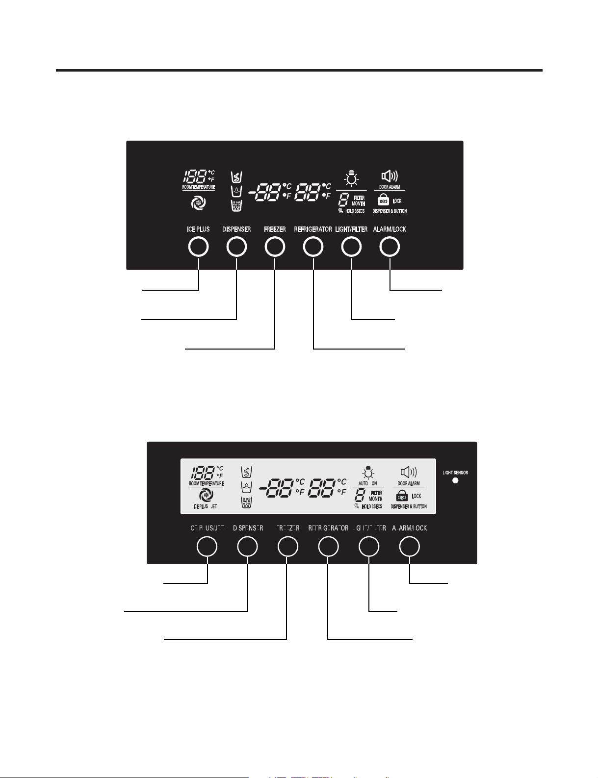
MICOM FUNCTION
Dispenser
Selection Button
Ice Plus Freezer
Selection Button
Door Alarm Button/
Dispenser Lock Button
Dispenser Light On/Off Button/
Filter Status Display RESET Button
Temperature Adjust Button
For Refrigerator Compartment
Temperature Adjust Button
For Freezer Compartment
Dispenser
Selection Button
Ice Plus Freezer/Jet Freezer
Function Selection Button
Door Alarm Button/
Dispenser Lock Button
Dispenser Light Auto On/Off Button/
Filter Status Display RESET Button
Temperature Adjust Button
For Refrigerator Compartment
Temperature Adjust Button
For Freezer Compartment
1. Monitor Panel
1-1. GR-L277SV(S)VA (LSC27950SW, LSC27950SB, LSC27950ST)
1-2. GR-L277SSWA (LSC27960ST)
- 11 -
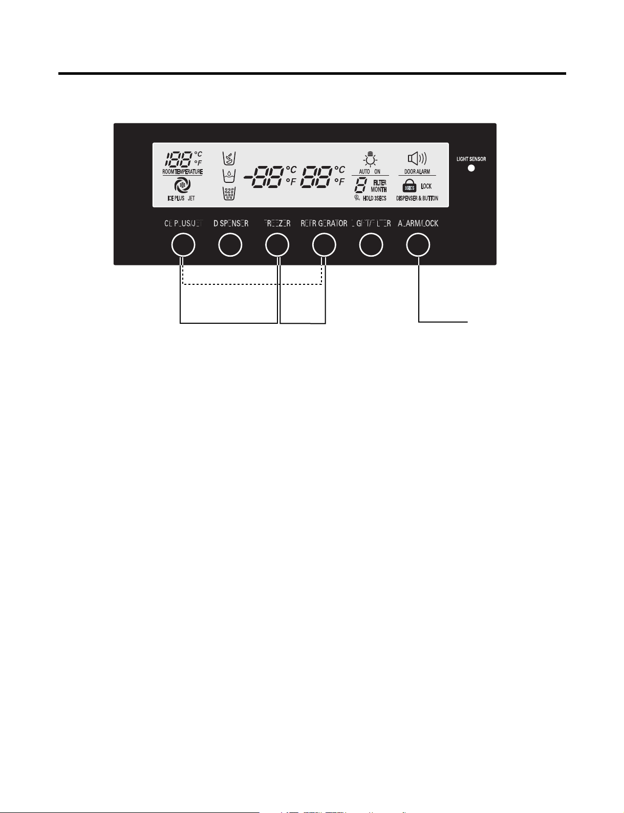
MICOM FUNCTION
Display Power
Saving Mode
Demo Mode
Change Display Degree from
Fahrenheit to Centigrade Mode
Buzzer Mute Mode
1-3. Display Second Function
1. Door Alarm Buzzer Mute Mode
Press ALARM/LOCK to turn the buzzer on or off.
2. Display Power saving Mode
It places display in standby mode until door is opened.
Press FREEZER and ICE PLUS/JET buttons simultaneously to turn all LEDs ON and then OFF with the recognition
sound of Ding~ after 5 seconds. (Be sure not to press only one button to work.)
Once the mode activates, the display is always OFF. Until door is opened or display button is pressed. When 20 seconds
has elapsed after closing door or pressing button, the display turns OFF. To deactivate this mode is same as the
activation methods. The mode inactivates when resetting the power.
3. Change Display Degree to Centigrade Mode from Fahrenheit Mode
To change temperature display from Fahrenheit to Celsius press and hold FREEZER and REFRIGERATOR buttons
simultaneously for more than 5 seconds. Do the same to convert back to Celsius.
4. Exhibition Mode
Demo mode is available for displaying the refrigerator in a sales setting or similar condition.
It allows the display, dispenser, lights, and fan to operate without running the compressor.
To enter the DEMO mode, press and hold the REFRIGERATOR and ICE PULS/JET buttons simultaneously for 5
seconds until the Ding~ sounds.
To exit the DEMO mode and return to normal operation, press and hold the REFRIGERATOR and ICE PULS/JET buttons
simultaneously for 5 seconds until the Ding~ sounds again.
The refrigerator will default to the NORMAL mode (DEMO mode OFF) if the power fails.
- 12 -
MICOM FUNCTION
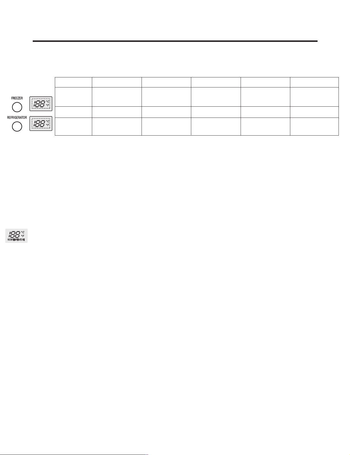
2. Description of Function
2-1-1. Function of Temperature Selection
Division Power Initially On 1st Press 2st Press 3th Press 4th Press
Temperature
Control
Freezer Control
Refrigeration
Control
* The temperature can vary ±5°F (±3°C) depending on the load condition.
❉ Whenever pressing button, setting is repeated in the order of COLD ➝ COLDER ➝ COLDEST ➝ COOL ➝ COLDER.
• The actual inner temperature varies depending on the food status, as the indicated setting temperature is a target
temperature, not actual temperature within refrigerator.
• Refrigeration function is weak in the initial time. Please adjust temperature as above after using refrigerator for minimum
2~3 days.
• Freezer Notch is fixed COLDER unconcerned with display Notch during Icemaking Control Mode and Icemaker Stop
switch is selected with ON.
2-1-2. Outside temperature display function
1. The ambient temperature sensor is located under the upper right hinge cover. This sensor reads the temperature of the
room and displays it in the upper right corner of the display.
2. The ambient temperature is displayed between 16 °F and 120 °F. Outside of that range, the display will show Er.
3. Since the ambient temperature sensor is located at the hinge, its reading may differ from other thermometers in the room.
COLD COLDER COLDEST COOL COOLER
-2 °F -5 °F -8 °F 7 °F 1 °F
37 °F 34 °F 32 °F 46 °F 41 °F
- 13 -
MICOM FUNCTION
LOCK
DISPENSER & BUTTON
3 SECS
LOCK
DISPENSER & BUTTON
3 SECS
LOCK LOCK again
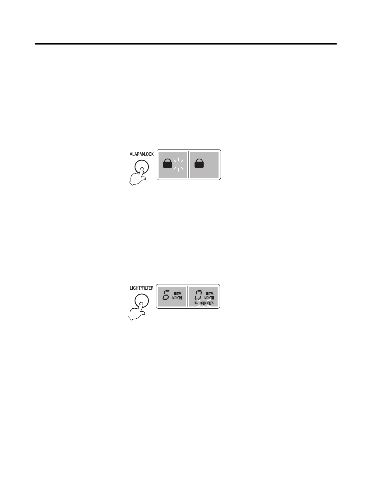
2-1-3. Lock function (dispenser and display button lock)
1. In power application of refrigerator, the LOCK text is turned off at the right side of lock graphic of display with the lock
replease status.
2. If desiring to lock the dislay the dispenser and control panel, push on the LOCK button more than 3 seconds. LOCK is
turned on at the right side of lock graphic of display with lock status.
3. The buzzer sound and control panel and dispenser function is not performed even if pressing display button other than
lock key in the lock status.
4. If desiring to release the lock status and pressing the lock button more than 3 seconds. LOCK text is turned off at the right
side of lock graphic of display with the lock release status.
LED
2-1-4. Filter condition display function
1. There is a replacement indicator light for the water filter cartridge on the dispenser.
2. Water filter needs replacement once six months.
3. Water filter light and FILTER RESET HOLD 3SECS text turn on to tell you need to replace the filter soon.
4. After replacing the filter, press and hold the lock button more than 3seconds.
Then water filter light and FILTER RESET HOLD 3SECS text turn off with reset status.
- 14 -
MICOM FUNCTION
DISPENSER
Pressing
Switch
LED (GR-L277SV(S)VA)
(LSC27950SW, LSC27950SB, LSC27950ST)
LCD (GR-L277SSWA) (LSC27960ST)
ON ON OFF
LED (GR-L277SV(S)VA) LCD (GR-L277SSWA)
(LSC27960ST)
(LSC27950SW, LSC27950SB, LSC27950ST)
DISPENSER
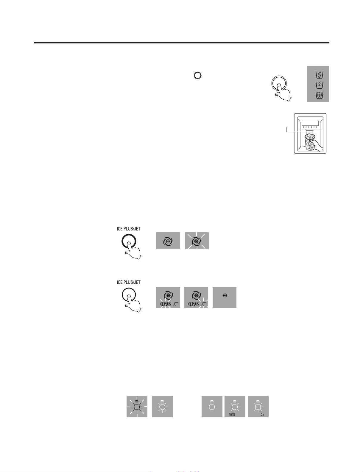
2-2. Dispenser use selection
You can select water or ice.
❉ Select WATER, CRUSHED ICE, or CUBED ICE by pressing the button as
you desire.
❉ Use your cup to press lightly on the actuator.
• Each graphic is indicated for the selected function.
• You’ll hear a CLICK when the ice door closes 5 seconds after ice is dispensed.
REFERENCE : Hold your cup in the dispenser for a few seconds after dispensing
ice or water to catch the last few drops or pieces of ice.
2-3. ICE PLUS Freezing/JET Freezing Selection
Select this function to expedite freezing.
• Press the button to cycle to toggle between the settings.
• The arrow mark graphic remains at the ON status after flickering 4 times when selecting Special Refrigeration ICE PLUS
FRZ or JET FRZ.
• ICE PLUS freezer or JET freezer function automatically turns off after a set time.
• Jet Freezing : Not applicable to all models.
2-4. Dispenser Light
• The dispenser light function is repeated following below whenever pressing LIGHT/FILTER button.
• Auto mode is automatic control of the dispender light by using the light sensor.
- 15 -

MICOM FUNCTION
2-5. ICE PLUS freezing
1. ICE PLUS freezing is a function to increase the cooling speed of the freezer compartment by running both the
compressor and the fan simultaneously.
2. ICE PLUS is cancelled and the refrigerator returns to its default setting in the event of a power interruption.
3. Selecting ICE PLUS changes only the speed of the cooling without affecting the set temperature.
4. The temperature can be adjusted even when ICE PLUS has been selected and is in progress.
5. The freezer operates at whatever temperature was set at the time ICE PLUS was selected.
6. If you select ICE PLUS, the compressor and fan will run until it is deselected or the cycle time has elapsed.
(3 hours : compressor and fan run / 3 ~ 24 hours : COLDEST operation)
7. If a defrost cycle occurs while an ICE PLUS is already running, ICE PLUS runs for its remaining cycle time after the
defrost cycle is completed. If the defrost cycle takes longer than 30 minutes, ICE PLUS will run for only 2 hours at the end
of the defrost cycle.
8. If you press ICE PLUS during a defrost cycle, the ICE PLUS indicator (LCD or LED, depending upon the model) will
illuminate but the compressor will not operate until the defrost cycle is complete.
9. If you press ICE PLUS within 7 minutes of compressor cut-off, the compressor will not operate until the 7-minute delay
has passed.
10. The freezer fan motor runs at high speed during the ICE PLUS cycle.
2-6. JET FREEZING (GR-L277SSWA / LSC27960ST)
1. JET FREEZING is a function to increase the cooling speed of the JET FREEZING compartment within the freezer by
running both the compressor and the JET FREEZING fan simultaneously.
2. JET FREEZING is cancelled and the refrigerator returns to its default setting in the event of a power interruption.
3. The display temperature is not changed by selecting JET FREEZING.
4. If JET FREEZING is selected, the compressor (after the 7-minute compressor delay time passes) and the freezer fan
motor will operate. The temperature in the refrigerator will drop and the fan motor will be off while the JET FREEZING
cycle runs, a maximum of 2 hours. The JET FREEZING indicator will go off at the end of the JET FREEZE cycle.
5. To prevent icing up, the JET FREEZING fan motor will cycle for 10 seconds every hour when JET FREEZING is not
selected.
6. If the JET FREEZING fan motor fails, this failure will not be detected because it is a 12-volt DC operation.
7. To check the JET FREEZING function, press and hold the FREEZER button or ICE PLUS/JET button for more than one
second. The JET FREEZE fan will operate.
- 16 -
MICOM FUNCTION
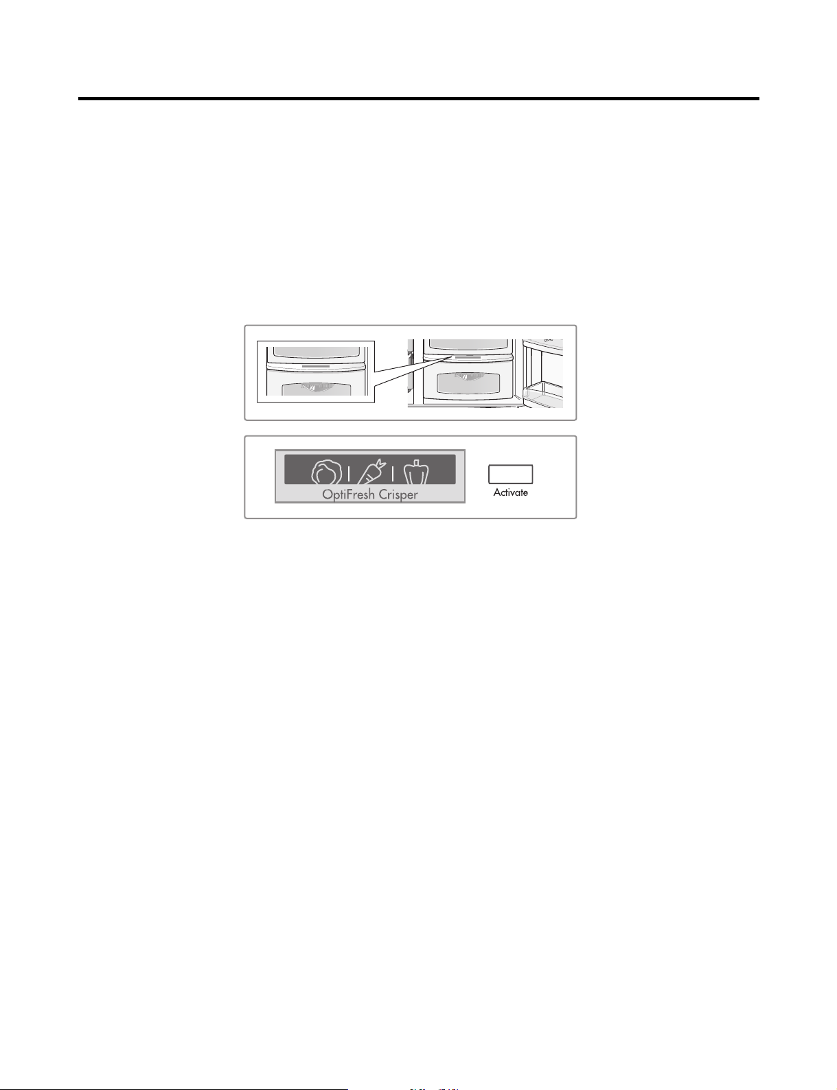
2-7. OptiFresh Function
1. The OptiFresh bin is positioned at the bottom of the refrigerator compartment and has a separate temperature control to
allow perfect storage of fruits and vegetables.
2. OptiFresh comprises of OptiFresh sensor at the rear of OptiFresh and a damper between OptiFresh and Freezer
compartment and a temperature adjusting display at the top of it.
3. When powered on, the initial NOTCH of OptiFresh display will be on OptiFresh Crisper.
If only the refrigerator door is opened, the OptiFresh LED will be ON.
4. The OptiFresh sensor opens and closes the damper based on the temperature.
5. The OptiFresh damper will cycle every hour to prevent icing up.
• Press the button to toggle between ON and OFF.
- 17 -
MICOM FUNCTION
Doors of freezer,
refrigerator, or
home bar.
BUZZER
Closing
Opening
Less than
one minute
One minute
30
seconds30seconds30seconds
Opening
Closing Closing
3 Times 3 Times 3 Times 3 Times
2-8. Control of variable type freezing fan
1. To increase cooling speed and response to load, the MICOM will vary the speed of the freezer fan between low and high.
2. The MICOM runs the fan at high speed only at power-up and for ICE PLUS or JET FREEZING cycles, and runs at low
speed for all other settings.
3. If you open the freezer door, the refrigerator door, or the home bar door, and the freezer fan was running at high speed, it
will reduce to low speed. If it was running at low speed when a door was opened, it will turn off.
4. If the MICOM determines the BLDC fan motor is locked up, (no signal for 115 seconds) it will show a failure code on the
display and cut power to the fan. To power the fan again, unplug the refrigerator for a few seconds and plug it in again.
2-9. Control of cooling fan motor
1. The cooling fan motor performs ON/OFF control by linking with the COMPRESSOR.
2. It controls at the single RPM without varying RPM.
3. Failure sensing method is same as in fan motor of freezing fan motor (refer to failure diagnosis function table for failure
display).
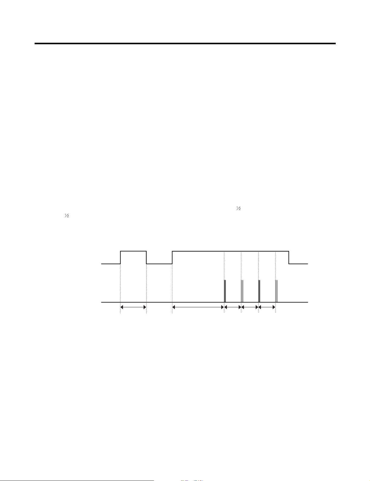
2-10. Door opening alarm
1. The buzzer sounds when any door is held open for more than one minute.
2. After any door has been open for one minute, the buzzer sounds three times for
times for
3. When all open doors have been closed, the buzzer stops.
second each every thirty seconds until the door is closed.
second each, then it sounds three
2-11. Ringing of button selection buzzer
1. If pressing the front display button, Ding ~ sound rings.
- 18 -

MICOM FUNCTION
2-12. Ringing of manual operation, manual frost defrost buzzer
1. The buzzer sounds briefly when the test button on the main PCB is pressed.
2
2. If you select manual operation, the buzzer sounds three times for
second each every thirty seconds until the door is closed.
3. If you select manual defrost, the buzzer sounds three times for
each every thirty seconds until the door is closed.
2-13. Defrost function
1. Defrost is cycled whenever the compressor’s runtime reaches 7 ~ 7 hours.
2. In providing initial power (or returning power failure), defrost starts whenever total operation time of compressor becomes
4 ~ 4
3. Defrost is completed if temperature of a frost removal sensor becomes more than 5°C after starting frost removal. Poor
frost removal is not displaced if it does not arrive at 5°C even if two hours have passed after starting frost removal.
4. No defrost cycle is run if the defrost sensor fails.
hour.
2-14. Refrigerator room lamp automatic off
• Refrigerator room lamp turn on and off by refrigerator door switch.
• If refrigerator room lamp continuously turns on more than 7 minutes, the refrigerator room lamp turns off automatically.
/10second each, then it sounds three times for 2/
2
/10second each, then it sounds three times for 2/
10
second
10
- 19 -

MICOM FUNCTION
POWER
ON
COMP
ON
F-FAN
&
C-FAN
ON
R-STEP
MOTOR
DAMPER
ON
OPTICHILL
STEP
DAMPER
MOTOR
ON
FROST
REMOVAL
HEATER
OFF
FROST
REMOVAL
HEATER
ON
DAMPER
&
DUCT DOOR
&
OPTICHILL
HEATER ON
DAMPER
&
DUCT DOOR
&
OPTICHILL
HEATER OFF
0.3
sec.
6.0
sec.
0.3
sec.
0.3
sec.
0.3
sec.
0.3
sec.
PIPE
&
DISP'
HEATER
OFF
0.3
sec.
COMP
ON
0.3
sec.
F-FAN
&
C-FAN
ON
0.3
sec.
R-STEP
MOTOR
DAMPER
ON
0.3
sec.
OPTICHILL
STEP
DAMPER
MOTOR
ON
PIPE
&
DISP'
HEATER
ON
TEST
SWITCH
(PRESS
Once)
OTHER
LOAD
OFF
COMP
ON
F-FAN
&
C-FAN
ON
R-STEP
MOTOR
DAMPER
ON
OPTICHILL
STEP
DAMPER
MOTOR
CLOSE
TEST
SWITCH
(PRESS
2 Times)
COMP
OFF
F-FAN
&
C-FAN
OFF
FROST
REMOVAL
HEATER
ON
R-STEP
MOTOR
DAMPER
CLOSE
0.3
sec.
0.3
sec.
0.3
sec.
0.3
sec.
0.3
sec.
0.3
sec.
0.3
sec.
0.3
sec.
0.3
sec.
0.3
sec.
0.3
sec.
POWER
ON
2-15. Sequential operation of components
Component products such as compressor, frost removal heater, freezing room fan, cooling fan, and step motor damper are
sequentially operated as follows for preventing noise and part damage occurred due to simultaneous operation of many
parts in applying initial power and completing test.
Function Load Operation Sequence Remark
When temperature
of a frost removal
sensor becomes
more than 45°C
If error occurs
during operation,
initial operation is
not done.
(At purchase,
shipping)
In applying Initial power TEST MODE
When
temperature of a
frost removal
sensor becomes
less than 45°C
(In power failure,
■
Sequence of
load operation
when closing
FREEZER and
REFRIGERATOR.
service)
Test mode 1
(Manual function)
If you press the
switch in the
again test mode 2
or temperature of
a frost removal
sensor is more
Test mode 2
(Manual frost
removal)
than 5°C, it
immediately
returns to the test
mode for initial
operation
(COMPRESSOR
operates after 7
minutes).
- 20 -
MICOM FUNCTION
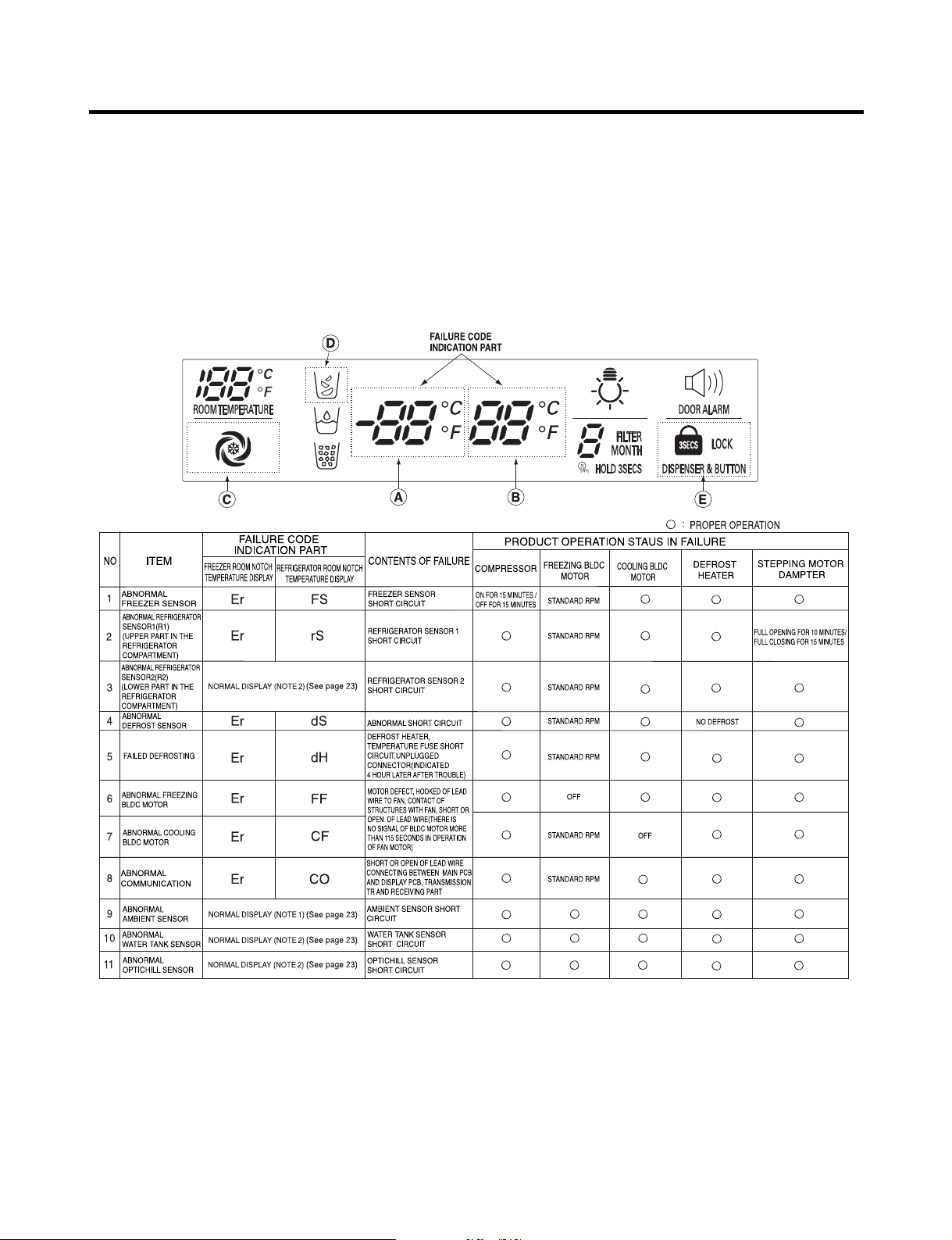
2-16. Failure Diagnosis Function
1. Failure diagnosis facilitates service when a failure code shows during product operation.
2. When a failure is detected, the buttons are deactivated.
3. If a failure code is released, the MICOM resets and normal operation continues.
4. The failure code is displayed on the FRZ TEMP display. All display graphics that are not part of the failure code are
turned off
(1) GR-L277SV(S)VA (LSC27950SW, LSC27950SB, LSC27950ST)
- 21 -
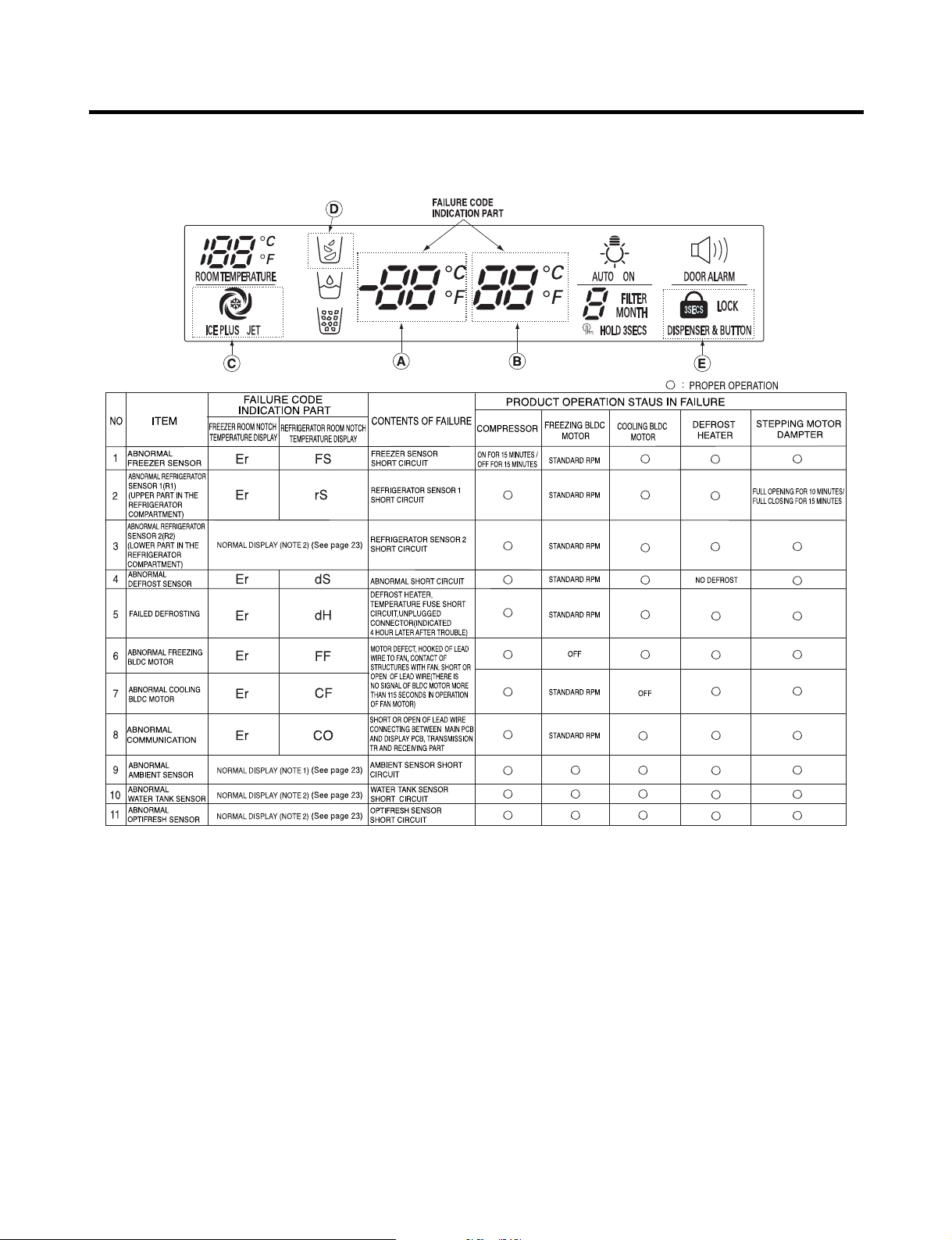
MICOM FUNCTION
(2) GR-L277SSWA (LSC27960ST)
- 22 -

MICOM FUNCTION
Note1) Freezer room notch temperature display and refrigerator room notch temperature display (failure code indication
part) are normally indicated in abnormal ambient sensor, and “Er” indicated on the ambient temperature dispaly
(except for the ambient temperature display, other display parts are indicated normally)
Note 2) R2-sensor, water-tank sensor and opti-fresh sensor is not indicated on the failure indicating part but indIicated in
checking all displaly parts (when pressing for more than the button of freezing temperature and quick rfeezing
button for more than 1 second).
R2-sensor (middle room)
Water-tank sensor
Opti-fresh sensor
Note 3) Freezer room notch temperature display and refrigerator room notch temperature display (Failure code indication
part) are normally indicated in abnormal ambient sensor, and Er indicated on the amvient temperature display
(except for the ambient temperature display, other LEDs or LCDs are indicated normally)
✻ LCD (LED) check function: If simultaneously pressing express freezer button and freezing temperature adjustment button
Normal:
Abnormal:
Normal:
Abnormal:
Normal:
Abnormal:
for a second, a back light is turned on and all display LCD (LED) graphics on. If releasing the
button, the LCD (LED) graphic displays the previous status, the back light is turned off (LCD
graphic and back light ON/OFF check).
display part graphic on the (C) part turns on
display part graphic on the (C) part turns off
display part graphic on the (D) part turns on
display part graphic on the (D) part turns off
display part graphic on the (E) part turns on
display part graphic on the (E) part turns off
The other
display
graphics turn
on
- 23 -

MICOM FUNCTION
2-17. Test Function
1. The test function assists in diagnosing the PWB and determining the exact mode of failure.
2. The test button is on the main PCB. When test mode is engaged, it will complete its test cycle and default to normal
operation within 2 hours.
3. The buttons are disabled while the test mode is in effect.
4. When you have finished running test mode, unplug the refrigerator to reset it to normal operation.
5. If a failure is detected during test mode, release the test mode to display the failure code.
6. If a failure code is displayed, the test mode cannot be started.
Mode Operation Contents Remarks
Test 1
Test 2
Normal
Status
Press test button once
(strong cold mode)
Press test button once at
the test mode 1 status
(forced defrost mode)
Press test button once at
the test mode 2 status
1. Continuous operation of compressor
2. Continuous operation of freezing BLDC motor
(high-speed RPM) and cooling BLDC motor
3. Defrost heater turns off
4. Stepping motor damper is completely opened
(baffle is closed)
5. OptiFresh stepping motor damper is
completely closed.
6. All display LEDs or LCD graphics turn on.
1. Compressor OFF
2. Freezing BLDC motor and cooling BLDC
motor turn off
3. Defrost heater turns on
4. Stepping motor damper is completely closed
(baffle is closed)
5. OptiFresh stepping motor damper is
completely closed.
Return to the initial status.
Freezer fan turns off when
door is opened.
Return to the normal mode
when the defrost sensor is
above +5°C (+41°F)
Compressor will operate
after delay for 7 minutes
TEST MODE 1 STATUS DISPLAY
TEST MODE 2 STATUS DISPLAY
- 24 -

MICOM FUNCTION
2-18. Dispenser Function
1. The dispenser allows serving ice and water without opening the door.
2. Pressing the dispenser switch dispenses crushed or cubed ice or water. If ice is selected, the switch operates the door
solenoid also. The door will close 5 seconds after the ice is dispensed.
3. If the freezer door is opened, the dispenser is deactivated.
4. If there is no OFF signal 3 minutes after the ice dispenser is activated, the auger and door solenoid are turned off.
The auger will stop immediately, but the door will not close for another 5 seconds.
5. The dispenser lamp turns on automatically if the crushed/cubed/water button is pressed or if the dispenser button is
pressed. It will turn off automatically shortly thereafter.
6. Selection function of water/crushed/cube ice
1) Select crushed/cubed/water. The display will show your selection.
2) If you select cubed ice, the auger is rotated to dispense cubes.
3) If you select crushed ice, the auger is rotated in the opposite direction to direct the cubes through the crusher.
7. Water dispenser function
1) If you select water, the display will indicate water.
2) The water dispenser uses a solenoid connected directly to the water pipe. Pressing the dispenser switch operates the
solenoid, which is at the right side of the back plate.
- 25 -
EXPLANATION FOR MICOM CIRCUIT
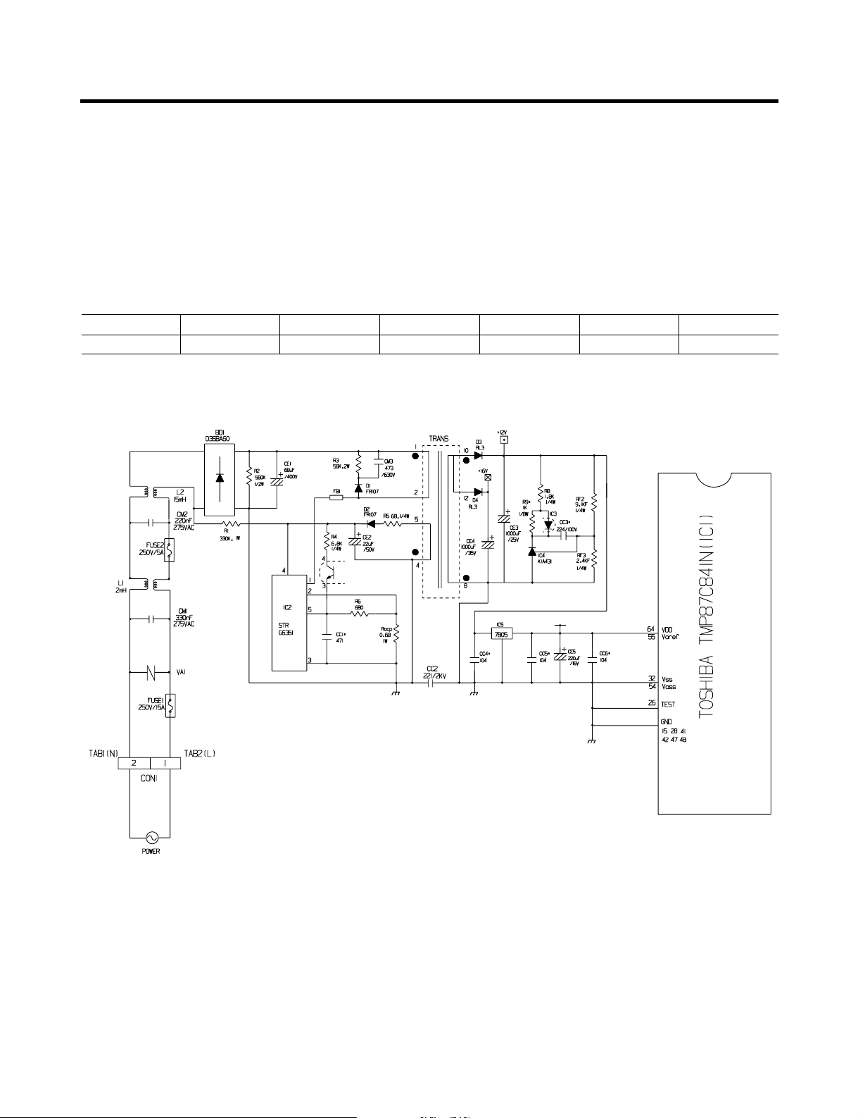
1. Explanation for PWB circuit
1-1. Power circuit
The power circuit includes a Switched Mode Power Supply (SMPS). It consists of a rectifier (BD1 and CE1) converting AC
to DC, a switch (IC2) switching the DC voltage, a transformer, and a feedback circuit (IC3 and IC4).
Caution : Since high voltage (160 Vdc) is maintained at the power terminal, wait at least 3 minutes after unplugging the
appliance to check the voltages to allow the current to dissipate.
Voltage of every part is as follows:
Part VA1 CE1 CE2 CE3 CE4 CE5
Voltage 120 Vac 160 Vdc 14 Vdc 12 Vdc 15.5 Vdc 5 Vdc
(1) GR-L277SV(S)VA, SSWA (LSC27950SW, LSC27950SB, LSC27950ST, LSC27960ST)
- 26 -

EXPLANATION FOR MICOM CIRCUIT
1-2. Oscillation circuit
The oscillation circuit generates a basic clock signal for synchronization and time calculation related to the transmission of
data and calculations made by the MICOM (IC1). The oscillator (OSC1) must always be replaced with an exact replacement
part. If this specification is changed, the change will affect the time calculations of the MICOM and it might not work at all.
(1) GR-L277SV(S)VA, SSWA (LSC27950SW, LSC27950SB, LSC27950ST, LSC27960ST)
- 27 -
EXPLANATION FOR MICOM CIRCUIT
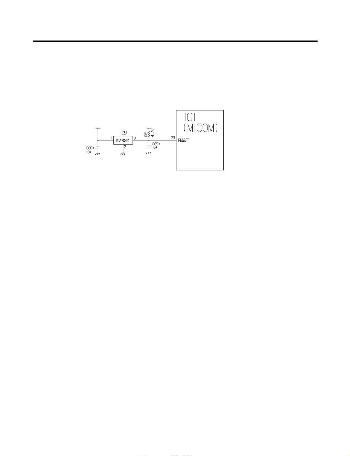
1-3. Reset circuit
The RESET circuit allows various parts of the MICOM, such as RAM, defrosting, etc., to be restarted from the initial state
when power is interrupted or restored. A LOW signal applied to the reset terminal for 10 ms causes the MICOM to reset
itself. During normal operation, the voltage at the reset terminal is 5 Vdc. If the reset fails, the MICOM will not operate.
(1) GR-L277SV(S)VA, SSWA (LSC27950SW, LSC27950SB, LSC27950ST, LSC27960ST)
- 28 -
EXPLANATION FOR MICOM CIRCUIT
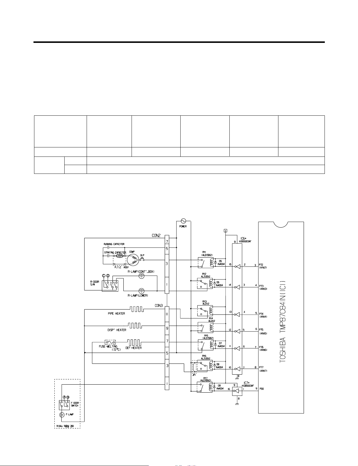
1-4. Load/dispenser operation, door opening circuit
1. LOAD DRIVING CIRCUIT
✽ The fan operates at the regular speed even if the door of the refrigerator or freezer is opened. When the doors are closed,
the fan reverts to its original speed.
✽ (A), (B), (C), and (D) of door switch for the freezer or refrigerator are connected to the door open sensing circuit in parallel
toward both ends of switch to determine door open at MICOM.
✽ In the TEST mode, the fan will stop if any door is opened. It will resume operation when the door is closed.
Type of Load Compressor
Measuring part (IC6) IC6-16 IC6-13 IC6-12 IC6-15 IC6-14
Status
ON Within 1 V
OFF 12 V
Defrost
Heater
AC Converting
Relay
Refrigerator
LAMP
Dispenser
Heater
(1) GR-L277SV(S)VA, SSWA (LSC27950SW, LSC27950SB, LSC27950ST, LSC27960ST)
- 29 -
EXPLANATION FOR MICOM CIRCUIT
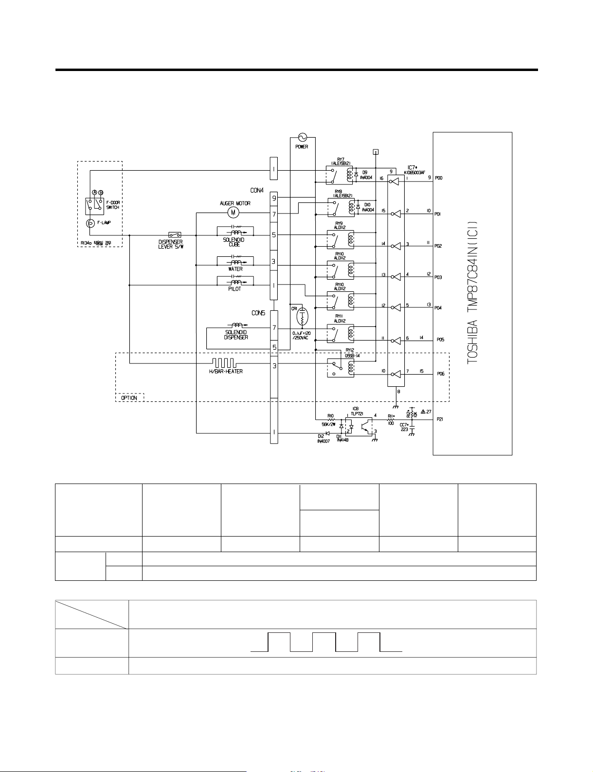
1-5. Dispenser operation circuit
(1) GR-L277SV(S)VA, SSWA (LSC27950SW, LSC27950SB, LSC27950ST, LSC27960ST)
1) Check load driving status
Type of Load
Measuring part IC7-15 IC7-14 IC7-13 IC7-12 IC7-11
Status
2) Lever Switch sensing circuit
Measuring part
Lever S/W
On
OFF 5V
ON Within 1 V
OFF 12 V
GEARED
MOTOR
SOLENOID
CUBE
5 V
0 V
WATER VALVE
WATER
IC1(Micom) (No. 16)
PILOT
VALVE
(60 Hz)
DISPENSER
- 30 -
SOLENOID
 Loading...