

LG LS-C1260HD, LS-C1120CM, LS-C1420CM, LS-C1420CN, LS-C1260CD Service Manual
...
K
M
K
M
Room Air Conditioner
SERVICE MANUAL
MODEL : LS-B0760CM/B0760HM
LS-B0960CM/B0960HM
LS-B0962CM/B0962HM
LS-B0962CD/B0962HD
LS-B0960CD/B0960HD
LS-C1260CM/C1260HM
LS-C1260CD/C1260HD
LS-C1120CM/C1420CM
LS-C1420CN
CAUTION
BEFORE SERVICING THE UNIT,
READ THE "SAFETY PRECAUTIONS" IN THIS MANUAL.

Functions
......................................................................................................................................
3
Product Specifications (Cooling Only)
......................................................................................
5
Product Specifications (Cooling & Heating)
..............................................................................
6
Dimensions
...................................................................................................................................
7
Maximum Length of Pipe and Freon Extra Charge
...................................................................
9
Refrigeration Cycle Diagram
.....................................................................................................
10
Wiring Diagram
..........................................................................................................................
11
Operation Details
.......................................................................................................................
13
Display Function
........................................................................................................................
20
Self-diagnosis Function
............................................................................................................
20
Installation
..................................................................................................................................
21
Operation
....................................................................................................................................
39
Disassembly of the parts(Indoor Unit)
.....................................................................................
41
2-way, 3-way V alve
.....................................................................................................................
44
Cycle Troubleshooting Guide
...................................................................................................
51
Electronic Parts Troubleshooting Guide
..................................................................................
52
Electronic Control Device
.........................................................................................................
56
Schematic Diagram
....................................................................................................................
59
Exploded View & Replacement Parts List
...............................................................................
61
- 2 -
Contents
- 3 -
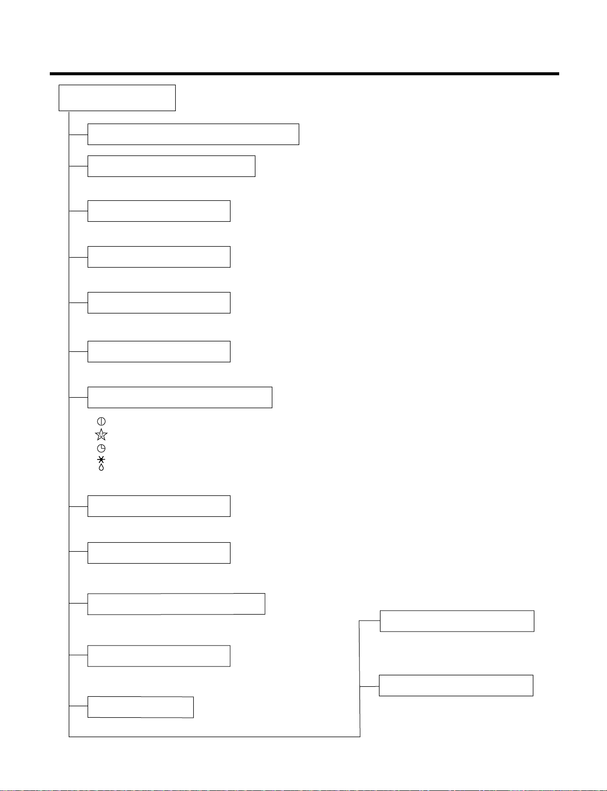
Functions
Indoor Unit
Operation ON/OFF by Remote controller
Sensing the Room Temperature
Room temperature control
Starting Current Control
Time Delay Safety Control
Indoor Fan Speed Control
Operation indication Lamps (LED)
Soft Dry Operation Mode
Sleep Mode Auto Control
Auto Air Control by CHAOS Logic
Airflow Direction Control
AUTO Wind
Deice(defrost) control(Heating)
Hot-start Control(Heating)
• Room temperature sensor(THERMISTOR).
• Maintains the room temperature in accordance with the Setting Temp.
• Indoor fan is delayed for 5 seconds at the starting.
• Restarting is inhibited for approx. 3 minutes.
• High, Med, Low, Chaos or Auto
• Intermittent operation of fan at low speed
• The louver can be set at the desired position or swing up
and down, right and left (not on all models) automatically.
• The fan speed is automatically switched from high to low speed.
• Both the indoor and outdoor fan stops
during deicing.
• Hot start after deice ends.
• The indoor fan stops until the
evaporator piping temperature will be
reached at 28°C.
• The fan is switched to low(Cooling), med(Heating) speed.
• The unit will be stopped after 1, 2, 3, 4, 5, 6, 7 hours.
• The fan is switched to intermittent or irregular operation.
• The fan speed is automatically switched from high to low speed.
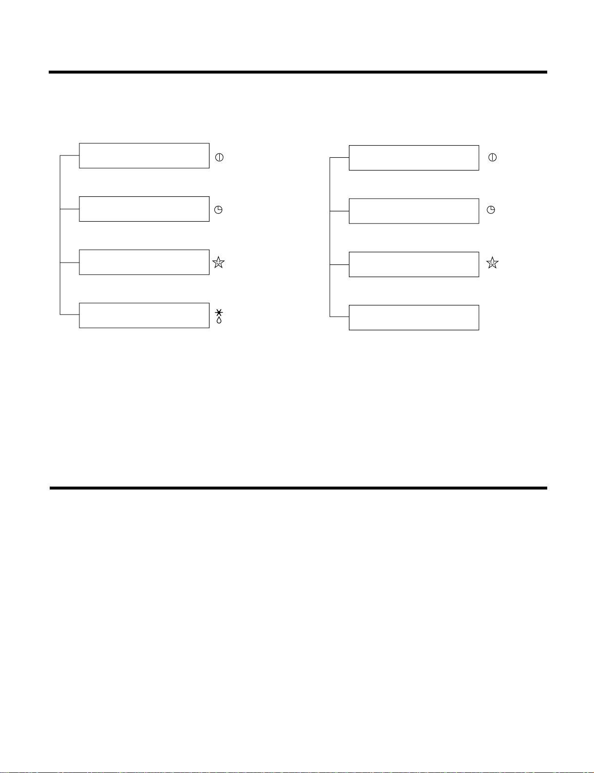
--- Lights up in Operation
--- Lights up in Sleep Mode
--- Lights up in Timer Mode
--- Lights up in Deice Mode or Hot Start Mode (only Heating Model)
--- Lights during in compressor running (for Cooling Model)
OUT
DOOR
- 4 -
TEMPERATURETEMPERATURE
LOWLOW
HIGHHIGH
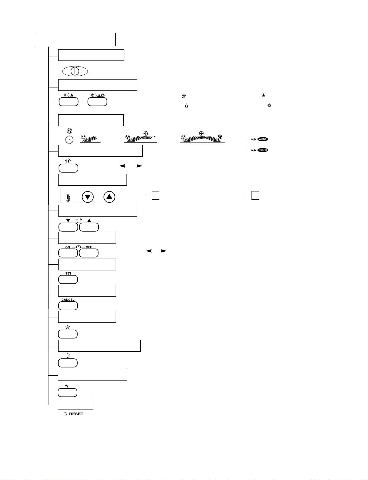
Remote Controller
Operation ON/OFF
(Cooling model only)
(Heatling model only)
Cooling Operation Mode ( )
Soft Dry Operation Mode ( )
(Low)
(Med)
(High)
(AUTO WIND)
(CHAOS)
: High: 39°C LOW : 11°C
Down to 18°C
Up to 30°C,
Cooling
: OFF, ON, OFF ON
: Cancel Sleep Mode, Timer ON or Timer OFF
: 1, 2, 3, 4, 5, 6, 7, Off Timer
: Fan Operates without cooling or heating.
Auto Operation Mode ( )
Heating Operation Mode ( )
Operation Mode Selection
Fan Speed Selection
Room, Temperature Display
Temperature Setting
Setting the Time or timer
Timer Selection
Timer Setting
Timer Cancel
Sleep Operation
Airflow Direction Control
Fan Operation Mode
Reset
Down to 16°C
Up to 30°C,
Heating
Cooling Capacity BTU/h(kcal/h)
Moisture Removal ℓ/h
Power Source Ø, V, Hz
Air Circulation m3/min
Noise Level dB(A)
Input W
Runnig Current A
E.E.R. BTU/h-W
Motor Output W
mm
Net. Weight kg
Refrigerant(R-22) g
Airflow Direction Control (Up & Down)
Remocon type
Service valve
Sleeping Operation
Drain Hose
Connecting Cable
Power Cord
- 5 -
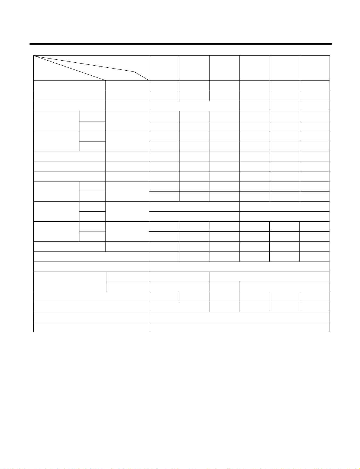
Product Specifications (Cooling Only)
7,300(1,840) 8,700(2,190) 8,700(2,190) 11,000(2,770) 12,000(3,020) 14,000(3,528)
1.0 1.2 1.2 1.2 1.7 1.7
1Ø, 220-240V, 50Hz
1Ø, 220V~,60Hz
1Ø, 220-240V,50Hz
1Ø, 220V~,60Hz
4.85 5.3 5.3 8.5 10.2 9.5
25 25 25 25 25 25
36±339±338±339±341±341±3
47±349±349±349±350±350±3
755 920 920 1,050 1,140 1,270
3.2 4.0 4.0 4.9 5.0 5.9
9.7 9.5 9.5 10.5 10.5 11
7 1010101515
25 25 25 25 25 25
810 x 220.5 x 152 900 x 290 x 183
660 x 540 x 260 801 x 555 x 262
6.5 6.5 6.5 10 10 10
27 27 27 33 33 35
540 670 690 1,080 840 980
OOOOOO
L.C.D Wireless
1/4"(6.35) 1/4"(6.35)
3 /8"(9.52) 3/8"(9.52) 1/2"(12.7)
OOOOOO
O OOOO
1.0mm
2
1.0mm
2
Model Name
Unit
Indoor
Outdoor
Indoor
Outdoor
Indoor
Outdoor
Indoor
Outdoor
Indoor
Outdoor
Liquid
Gas
Dimensions
(W x H x D)
Item
LS-B0760CM
LS-B0960CD
LS-B0960CM
LS-B0962CD
LS-B0962CM
LS-C1120CM
LS-C1260CD
LS-C1260CM
LS-C1420CM
LS-C1420CN
- 6 -
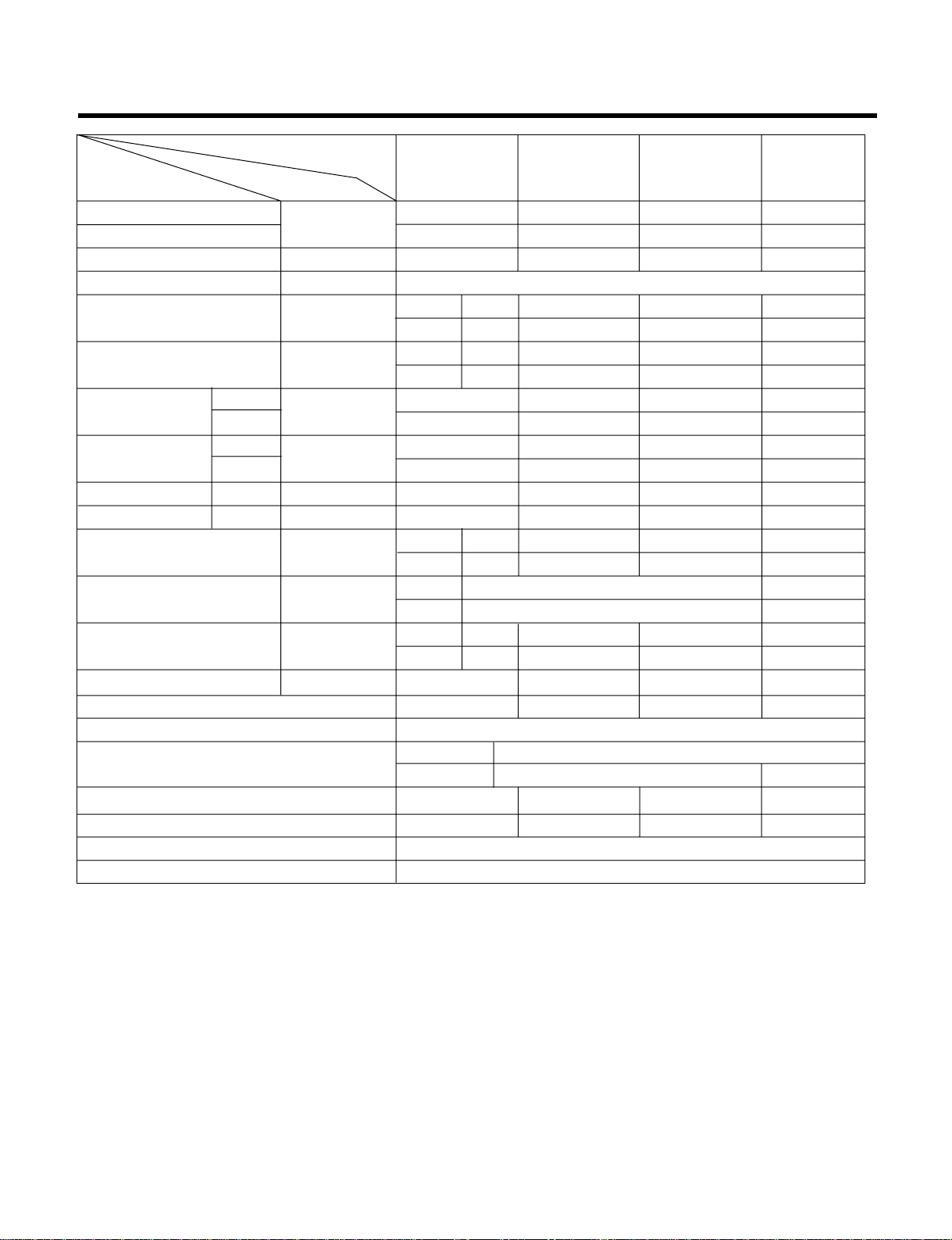
Product Specifications (Cooling & Heating)
Cooling Capacity
Heating Capacity
Moisture Removal ℓ/h
Power Source Ø, V, Hz
Air Circulation m3/min
Noise Level dB(A)
Input W
Runnig Current
A
E.E.R. BTU/h·W
C.O.P W/W
Motor Output W
mm
Net. weight kg
Refrigerant(R-22) g
Airflow Direction Control (Up & Down)
Remocon Type
Service Valve
Sleeping Operation
Drain Hose
Connecting Cable
Power Cord
7,000(1,764) 8,500(2,142) 8,500(2,142) 12,000(3,020)
7,500(1,890) 9,500(2,394) 9,500(2,394) 12,500(3,150)
1.0 1.2 1.2 1.7
1Ø, 220-240V, 50Hz
4.85 5.3 5.6 10.2
25 25 25 25
36±339±340±141±3
47±349±350±151±3
760 940 895 1,250
780 1,030 950 1,100
3.2 4.1 3.8 5.5
3.3 4.4 4.1 4.8
9.2 9.0 9.5 9.6
2.82 2.7 2.76 3.3
710 10 15
25 25 25 25
810 x 220.5 x 152
900 x 290 x 183
660 x 540 x 260
810 x 555 x 262
6.5 6.5 6.5 10
30 30 30 35
590 690 720 810
OOOO
L.C.D Wireless
1/4"(6.35)
3/8"(9.52) 1/2"(12.7)
OOOO
OOOO
1.0mm
2
1.0mm
2
Model Name
Unit
Indoor
Outdoor
Indoor
Outdoor
Cooling
Heating
Cooling
Heating
Cooling
Heating
Indoor
Outdoor
Indoor
Outdoor
Indoor
Outdoor
Liquid
Gas
Dimensions
(W x H x D)
Item
LS-B0760HM
LS-B0960HD
LS-B0960HM
LS-B0962HD
LS-B0962HM
LS-C1260HD
LS-C1260HM
BTU/h(kcal/h)
- 7 -
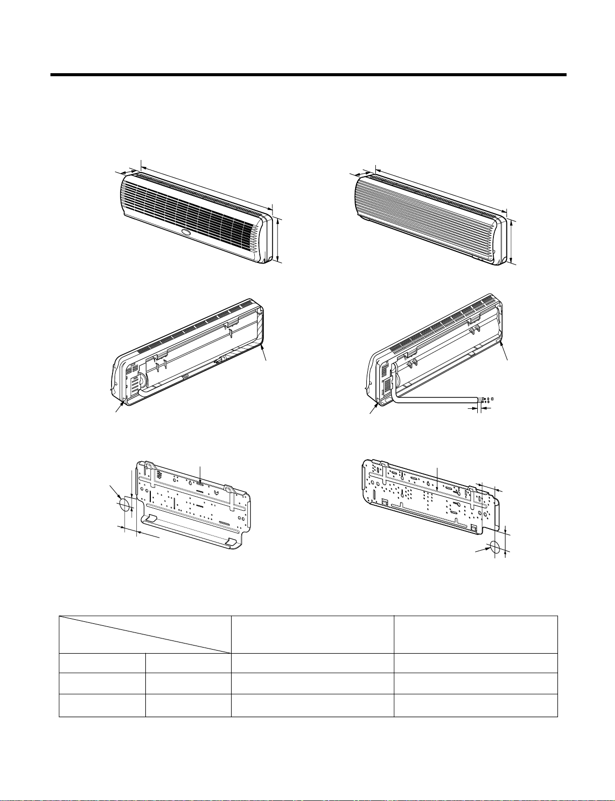
Dimensions
(1) Indoor Unit
4.5cm
4cm
50
8cm
2cm
W
W
D
D
H
H
Installation plate
Tubing hole cover
Tubing hole cover
Tubing hole cover
Tubing hole cover
Installation plate
Hole for piping
Hole for piping
(7K, 9K)
(11K, 12K, 14K)
MODEL 7K, 9K BTU 11K, 12K, 14K BTU
DIM Series Series
W mm 810 900
H mm 220.5 290
D mm 152 183
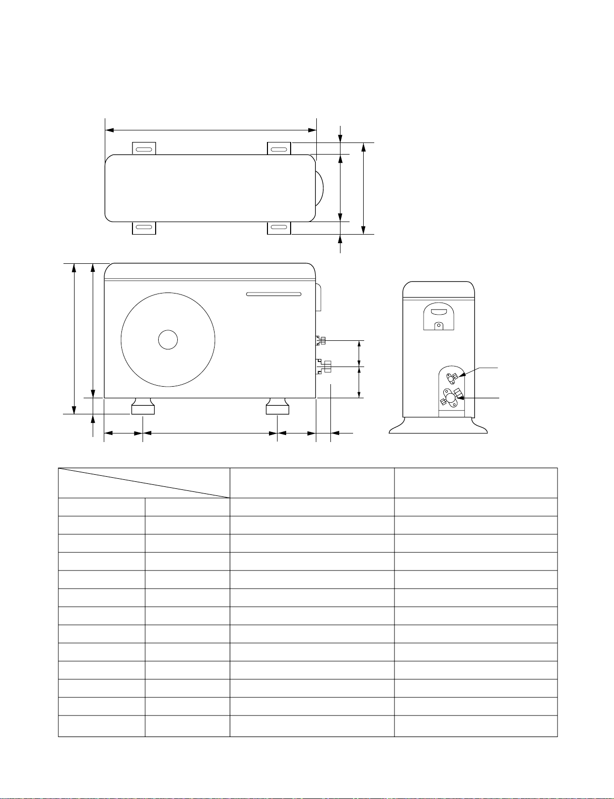
- 8 -
W
D
L1
L2
H
L3
L4
L5L6 L7 L8
L9
L10
Liquid side
2-way valve
Gas side
3-way valve
(2) Oudoor Unit (7K, 9K, 11K, 12K, 14K)
MODEL
7K, 9K, 11K BTU Series 12K, 14K BTU Series
DIM
W mm 660 801
H mm 540 555
D mm 260 262
L1 mm 297 339
L2 mm 18.5 37
L3 mm 523 543.6
L4 mm 17 11.4
L5 mm 447 591
L6 mm 76.5 105
L7 mm 76.5 105
L8 mm 66 72.5
L9 mm 82 86.4
L10 mm 77 77
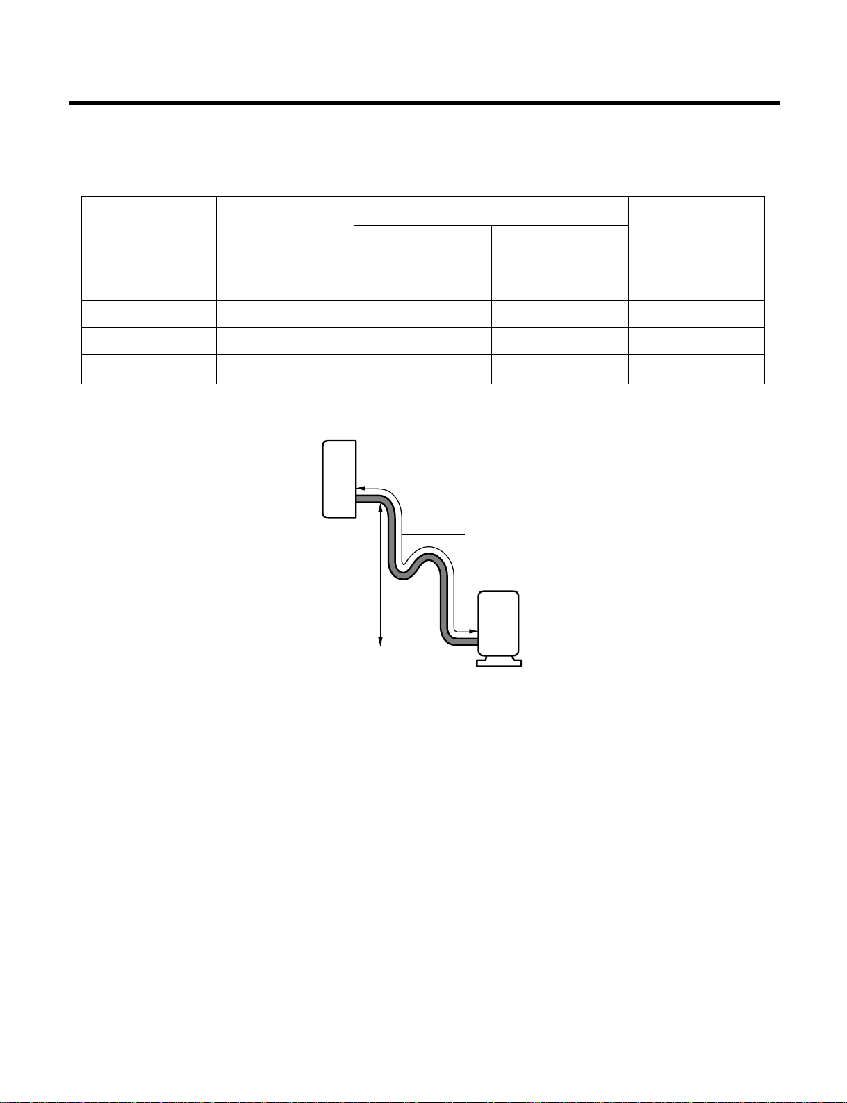
- 9 -
Maximum Length of Pipe and Freon Extra Charge
Charge amount per 1m
A
B
Oil trap
Outdoor unit
Indoor unit
Capacity STANDARD
MAXIMUM LENGTH Charge amount (g)
(Btu/h) LENGTH(m)
AB
per 1m
~7000 4 7 15 20
~9000 4 7 15 20
~12000 4 7 15 20
~18000 5 15 30(25) 40
~24000 5 15 25 40
* A, B mean indoor unit higher located than outdoor unit
* Capicity is based on standard length and maximum allowance length is the basis of relia-
bility.
* Oil trap should be installed per 10 meters.
* Numerical value in "( )" is for Rotary Comp. model.
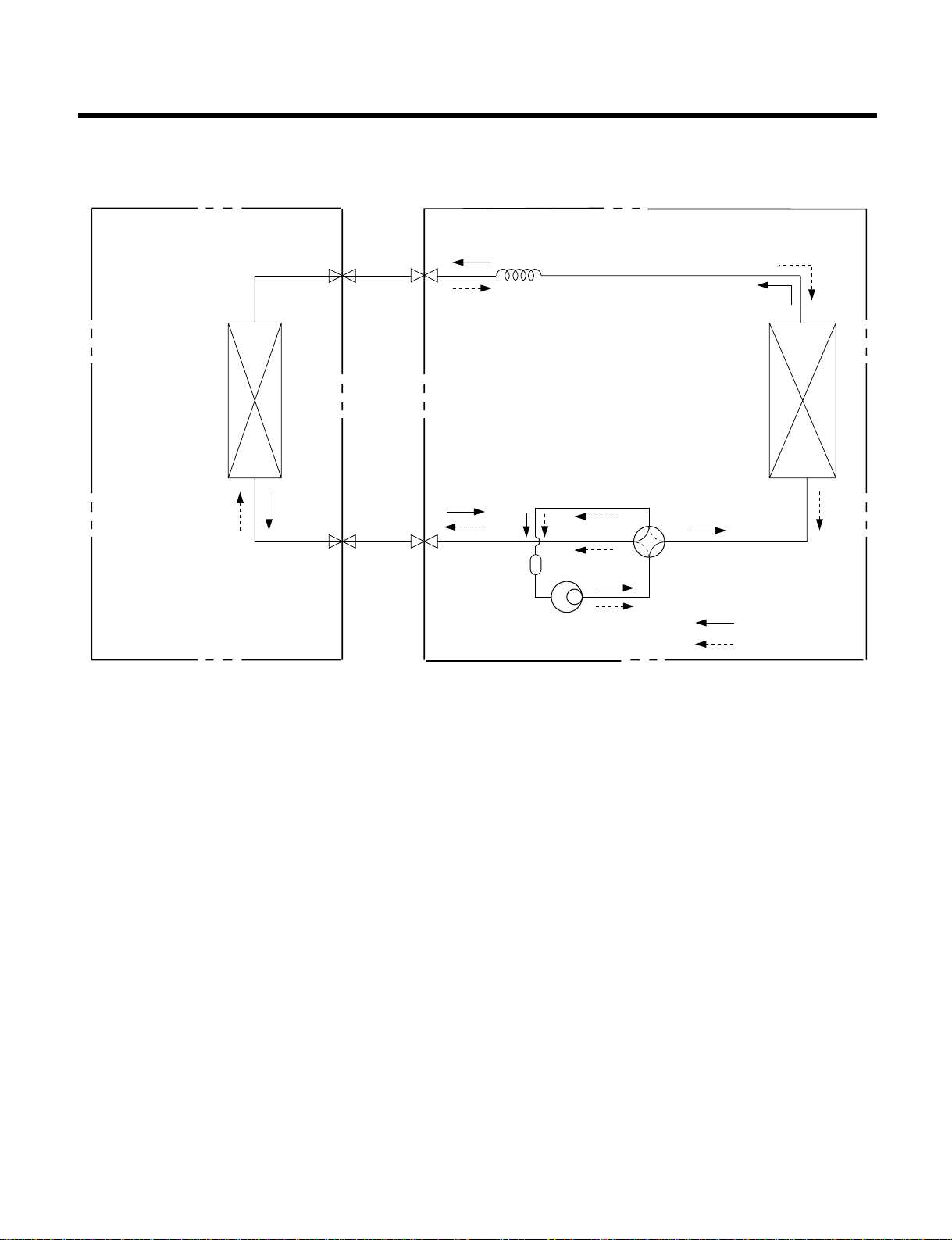
- 10 -
Refrigeration Cycle Diagram
INDOOR UNIT
HEAT
EXCHANGE
(EVAPORATOR)
HEAT
EXCHANGE
(CONDENSER)
COMPRESSOR
COOLING
HEATING
ACCUMULATOR
REVERSING
VALVE
GAS SIDE
CAPILLARY TUBE
LIQUID SIDE
2-WAY VALVE
3-WAY VALVE
OUTDOOR UNIT

- 11 -
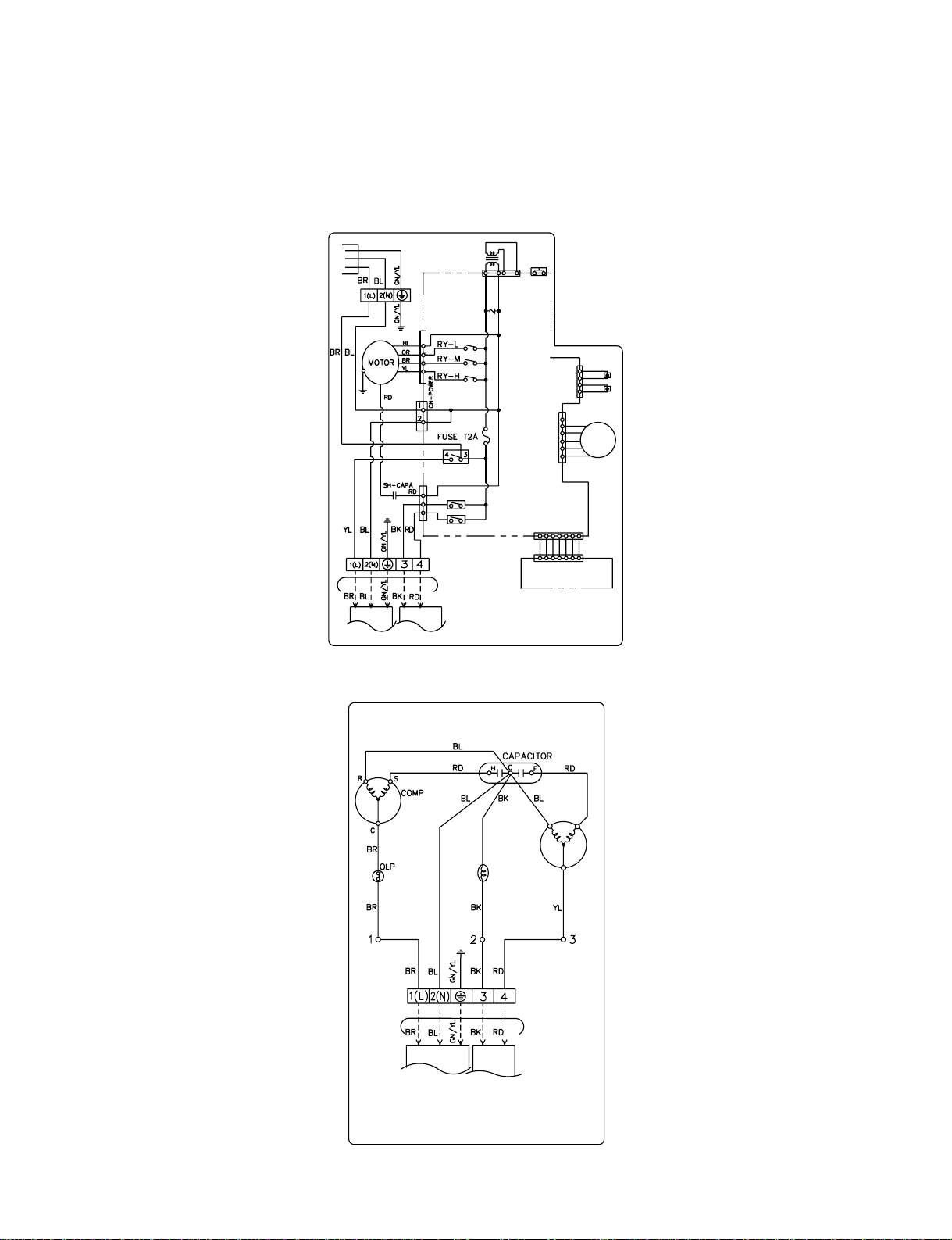
Wiring Diagram
(1) 7K, 9K, 11K, 12K, 14K BTU Cooling Only
1. Indoor Unit
2. Outdoor Unit
YL BL
YL
RD
SH-CAPA
OR
BR
BR
BR BL
GN/YL
POWER
BL
RY-L
RY-M
RY-H
MOTOR
STEP
MOTOR
GN/YN
PILLAR
TO OUTDOOR UNIT
CN-POWER
CN-FAN
CN-TRANS
CN-TH
THERMISTOR
RY-COMP
MAIN PCB
DISPLAY PCB ASM
ASM
CN-DISP
FUSE T2A
CN-UP/DOWN
1
2
43
TERMINAL
TRANS
FORCED
OPERATION
SWITCH
FORMER
N
INDOOR WIRING DIAGRAM
1
2
(N)(L)
1
2
(N)(L)
TRANS
FORMER
FORCED
OPERATION
SWITCH
THERMISTOR
PILLAR
TERMINAL
MAIN PCB
ASM
DISPLAY PCB ASM
INDOOR WIRING DIAGRAM
(7K, 9K, 12K)
(11K, 14K)
COMP
FAN
MOTOR
TO INDOOR UNIT
PILLAR
TERMINAL
OUTDOOR WIRING DIAGRAM
- 12 -
(2) 7K, 9K, 12K BTU Cooling & Heating
1. Indoor Unit
2. Outdoor Unit
POWER
CN-FAN
CN-TH
CN-UP/DOWN
TRANS
FORMER
THERMISTOR
CN-DISP
RY-FAN
RY-4W AY
CN-4WAY
RY-COMP
PILLAR
TERMINAL
TO OUTDOOR UNIT
DISPLAY PCB ASM
INDOOR WIRING DIAGRAM
MAIN PCB
ASM
STEP
MOTOR
CN-TRANS
FORCED
OPERATION
SWITCH
OUTDOOR WIRING DIAGRAM
TO INDOOR UNIT
PILLAR
TERMINAL
FAN
MOTOR
REVERSING
VALVE
1. Time Delay Safety Control
• 3min
...
The compressor is ceased for 3minutes to balance the pressure in the refrigeration cycle.
(Protection of compressor)
• 2sec
...
The indoor fan is ceased for 2sec. to prevent relay noise.
(Protection of fan relay and micro chip)
• 30sec
...
The 4-way valve is ceased for 30sec. to prevent the refrigerant-gas abnormal noise when the Heating
operation is OFF or switched to the other operation mode.
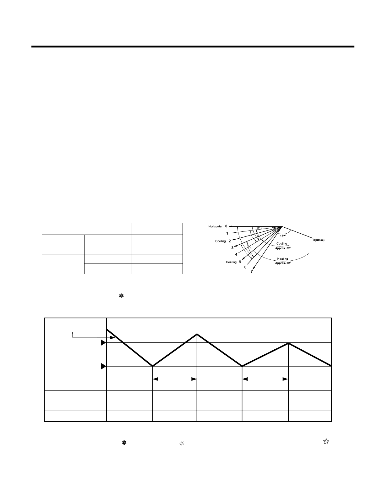
2. Airflow Direction Control
• This function is to swing the louver up and down automatically and to set it at the desired position.
• The procedure is as the following.
1st ;Press the ON/OFF Button to operate the product.
2nd ;Press the Airflow Direction Control Button to swing the louver up and down automatically.
3rd ;Repress the Airflow Direction Control Button to set the louver as the desired position.
3. Cooling Mode Operation
• When selecting the Cooling ( ) Mode Operation, the unit will operate according to the setting by the remote controller and the operation diagram is as following.
4. Cooling or Heating Mode with Sleep Mode Auto Operation
• When selecting the Cooling( ) or the Heating( ) combined with the Sleep Mode Auto Operation( ), the
operation diagram is as following.
- 13 -
Operation Details
Operating Mode Louver Position
Cooling
Start 2
Auto. Swing 1~4
Heating
Start 5
Auto. Swing 3~6
Selectig
fan speed
Intake Air temp.
More than
3 minutes
More than
3 minutes
Selecting
fan speed
Low
ON
OFF
ON ON
OFF
Low
Selectin
fan speed
COMP. ON
(SET TEMP.+0.5°C
COMP. OFF
(SET TEMP.-0.5°C
INDOOR FAN SPEED
COMPRESSOR
(1) The function of main control
- 14 -
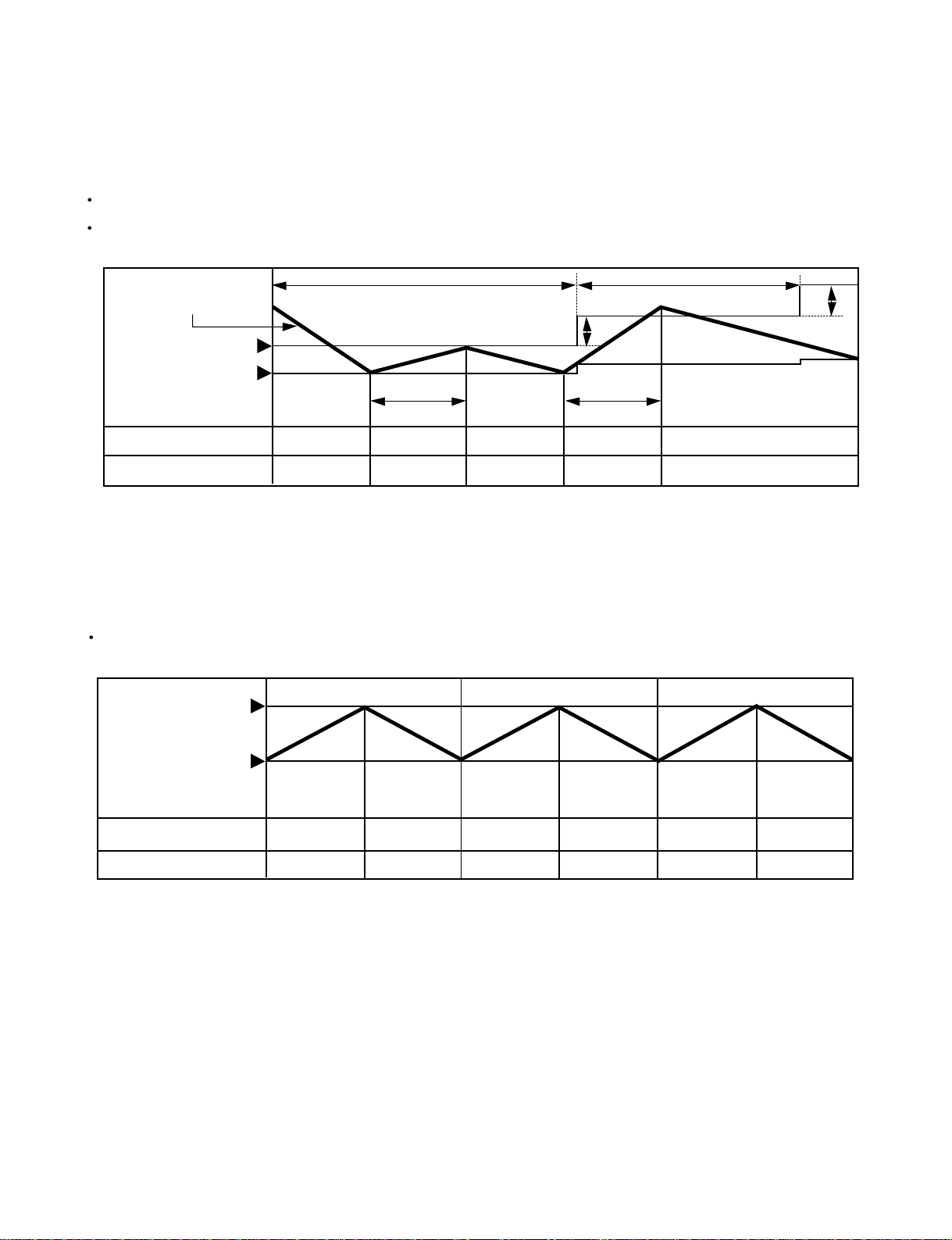
• Cooling Mode with the Sleep Mode
The setting temperature will be raised by 1°C 30minutes later and by 2°C 1 hour later.
The operation will be stopped after 1, 2, 3, 4, 5, 6, 7 hours.
• Heating Mode with the Sleep Mode.
The operation will be stopped after 1, 2, 3, 4, 5, 6, 7 hours.
Intake Air temp.
COMP. ON
(SET TEMP. +0.5°C
COMP. OFF
(SET TEMP. -0.5°C
INDOOR FAN SPEED
COMPRESSOR
ON OFF OFFON ON
Low Low Low Low
1°C
1°C
Low
30 minutes
30 minutes
More than
3 minutes
More than
3 minutes
SETTING TEMP. +3°C
(COMPRESSOR OFF)
SETTING TEMP.
(COMPRESSOR ON)
INDOOR FAN SPEED
COMPRESSOR
Med.
ON
ON
ON
Low or OFF Low or OFF Low or OFF
OFF
OFF
OFF
Med. Med.
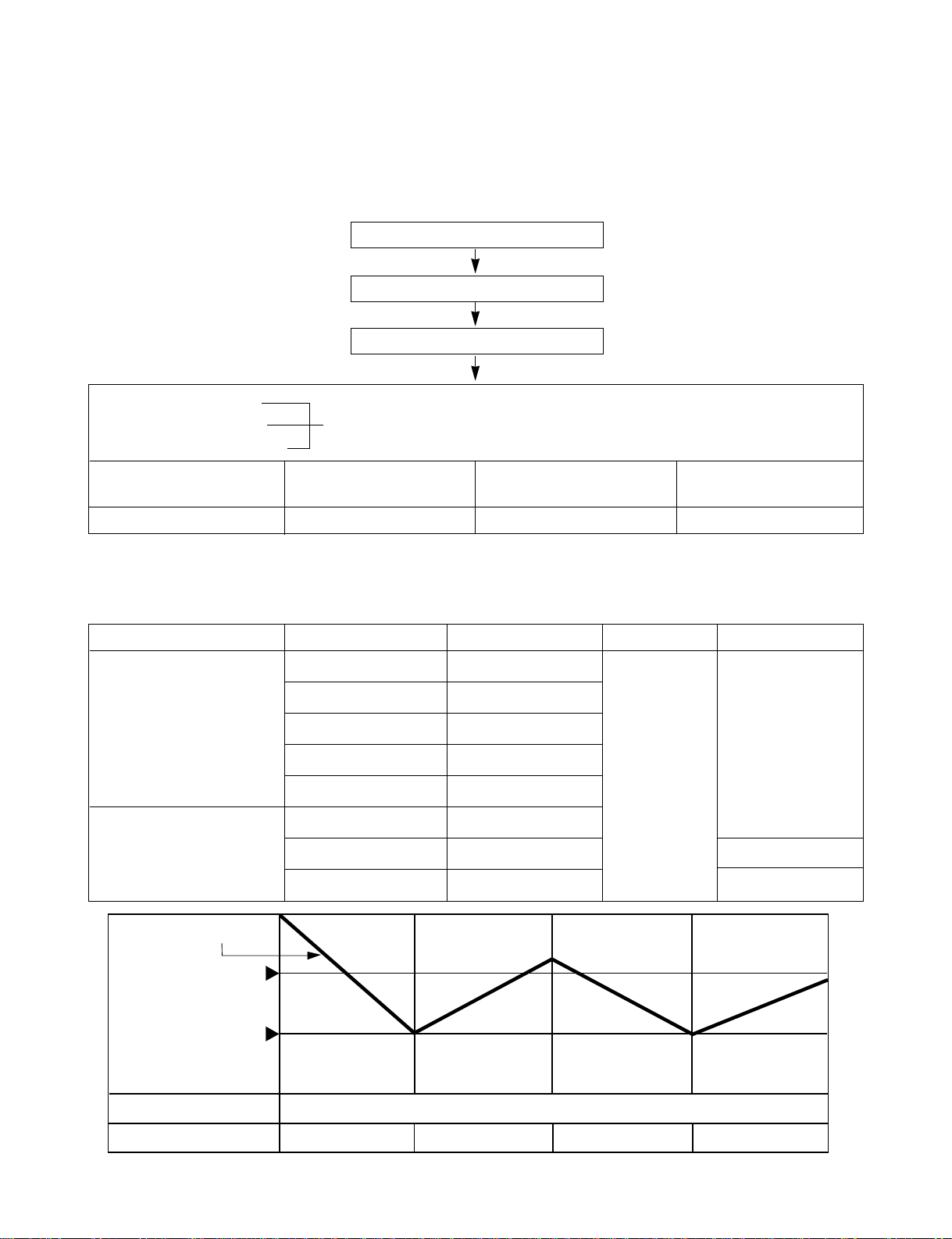
5. Auto Operation
• The operation procedure is as following.
❋ If initial mode is decided, that mode is continued despite of the room temperature changing.
• Auto Operation for Cooling
- 15 -
Press Start/Stop Button
Select Auto Operation Mode
Check the Room temperature
Operation mode
Indoor fan speed are automatically decided by Fuzzy rule.
Setting temperature
Intake-air
temperature
Operation Mode
Over below
21°C24
°
C
Soft Dry
below 21°C
Heating
Over 24°C
Cooling
~
Intake-Air temp.
Setting Temp. +0.5°C
(Compressor OFF)
Setting Temp. -0.5°C
(Compressor ON)
COMPRESSOR ON OFF ON OFF
INDOOR FAN SPEED Fuzzy Speed
Intake-air Temperature Setting Temperature
Over 26°C25°C
Over 24°C~below 26°C Intake air -1°C
Over 22°C~below 24°C Intake air -0.5°C
Over 20°C~below 22°C Intake air temperature
below 20°C20°C
Over 20°C~below 30°C Fuzzy control
below 20°C20°C
over 30°C30°C
Operation Condition
When Auto Operation
initial start
Controlled by
Fuzzy logic
1/f rhythm
Fan Speed Air DirectionControl
When Switch to Auto
Operation
■ Auto Operation for Soft Dry
The Setting temperature will be same that of the current intake-air temperature.
- Compressor ON temperature; Setting temperature +1°C
- Compressor OFF temperature; Setting temperature -0.5°C
■ Auto Operation for Heating
- 16 -
Intake Air temp. below 20°C Over 20°C~below 21°C
Setting temp. 20°C Intake air temperature +0.5°C
- 17 -
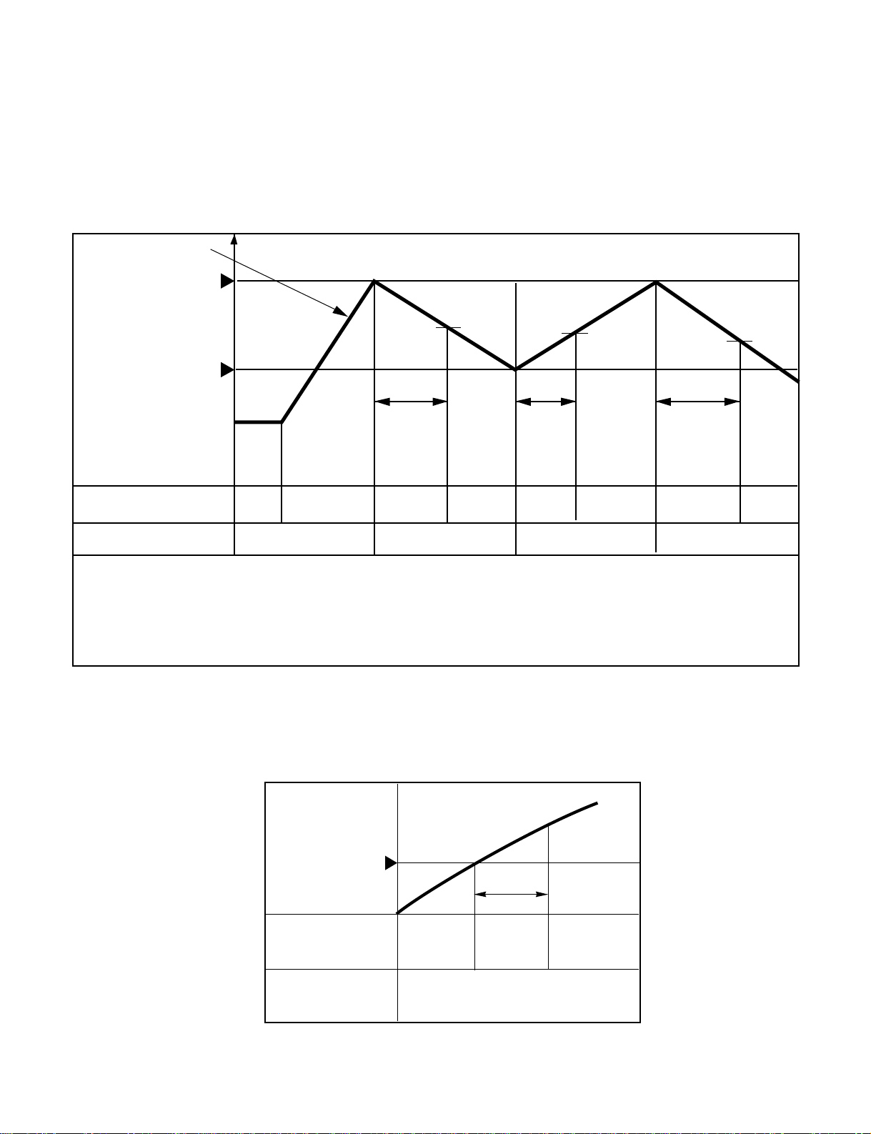
6.Heating Mode Operation
The unit will operate according to the setting by the remote controller and the operation diagram is shown as following.
For 9K, 12K Models
Intake Air temp.
Setting temp. +3°C
(Compressor OFF)
Setting temp.
(Compressor ON)
Selecting
fan speed
Selecting
fan speed
Hot
Start
A
B
A
minimum
10sec.
minimum
10sec.
minimum
10sec.
OFF
COMPRESSOR ON OFF ON OFF
• A point; The indoor pipe temperature to be 35°C.
The indoor fan operates minimum 10sec. even if falls lower than 35°C.
• B point; The indoor pipe temperature to be 35°C.
The indoor fan operates minimum 10sec. even if falls lower than 35°C.
INDOOR FAN SPEED LOW
OFF
LOW LOW OFF
7. Hot-Start Control
• The indoor fan stops until the evaporator piping temperature will be reached at 28°C. (BY TEMPERATURE)
• The operation diagram is as following.
PIPE
TEMP 28
°C
INDOOR
FAN SPEED
COMPRESSOR
ON
OFF
LOW
60 sec.
SELECTING
FAN SPEED
HOT-START BY TEMPERATURE
T1
T2
T1
T2
- 18 -
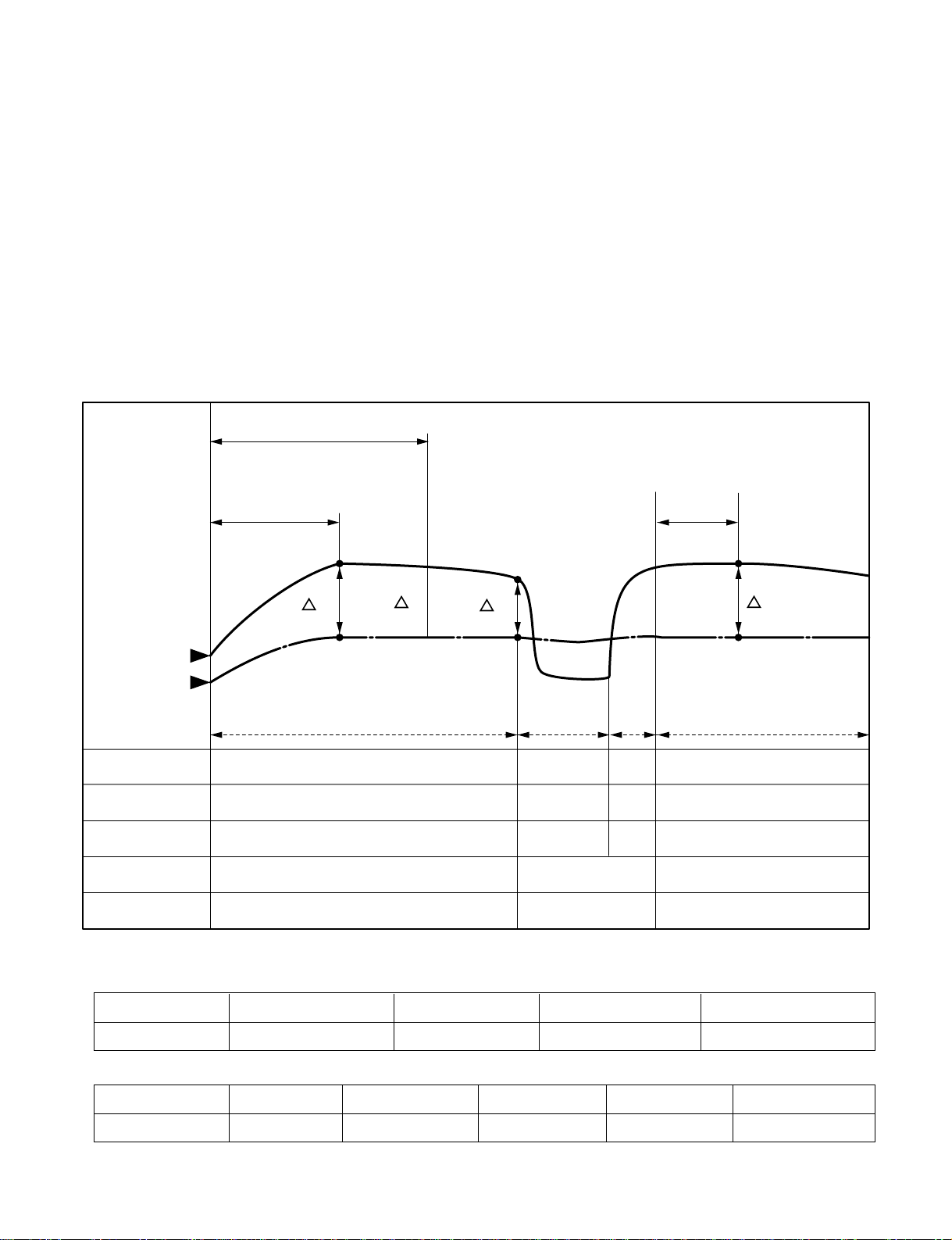
8. Deice Control
• Deicing operation is controlled by timer and sensing the indoor pipe temperature.
• Deicing operation checks the indoor pipe temperature and Intake-air temperature at 25 minutes and 60 minutes
on starting of heating operation, and discriminates by temperature difference.
• When the heating operation passed 25 minutes, the temperature (△T1=TE1–TR1) is checked and memorized
with checking the indoor pipe temperture (TE1) and the indoor Intake-air temperature (TR1).
• When the heating operation passed 60 minutes, deicing operation checks the indoor pipe temperature (TE2)
and the indoor Intake-air temperature (TR2), and checks indoor pipe temperature(TE2), the temperature
difference (△T2=TE2–TR2) and the temperature difference △Td(=△T1–△T2) of △T1, △T2.
If temperature of indoor pipe is below 32°C Deicing function operates at the priority I condition.
If temperature of indoor pipe is over 32°C Deicing function operates at the priority II condition.
If the temperature difference (△Td) become more than the option temperature, deicing operation starts.
• At that time, deicing operation time is decided.
• The deicing operation time starts after deicing operation started.
• If deicing operation start, above heating operation time is reset, so if deicing operation is finished, the heating
operation time is recounted.
• The deicinig time and the operation diagram are as following.
TEMP °C
60 minutes
25 mins
TE1
TE2
25 mins
Heating
Heating
ON
ON
ON
ON
ON
ON
ON
ON
ON
ON
OFF
OFF
OFF
OFF
ON(Heating Operation)
ON
ON
OFF
COMPRESSOR
4-WAY VALVE
OUTDOOR FAN
INDOOR FAN
DEICE LED
Deicing
Hot
Start
Pipe Temp.
Intake Air
Temp.
T1-T2=Td Over 3.5°C 3.0~3.5°C 2.5~3.0°C 2.0~2.5°C below 2.0°C
Deicing Time 12mins 11mins 10mins 9mins Heating Operation
TE2 below 30°C 30~31°C 31~32°C Over 32°C
Deicing Time 12mins 11mins 10mins Heating Operation
(DEICING DIAGRAM)
Priority I
Priority II
- 19 -
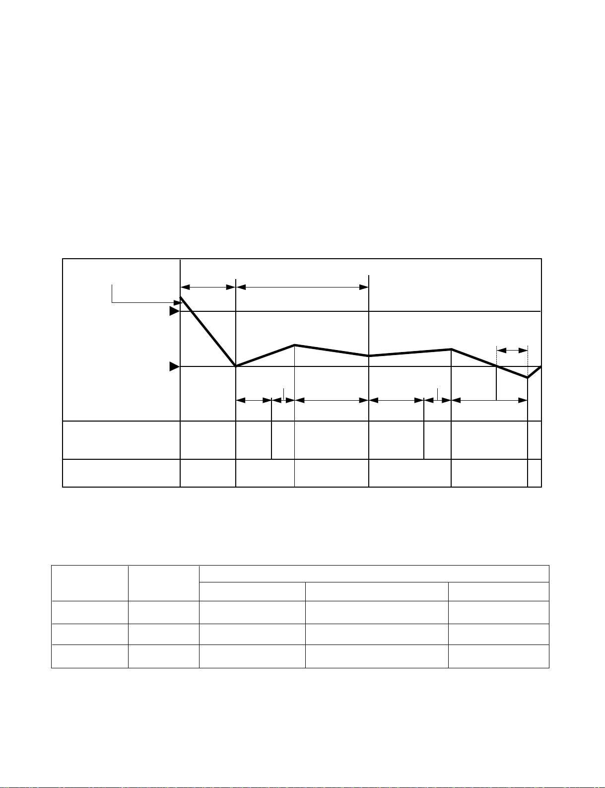
9. Soft Dry Operation.
• During Soft Dry Operation, the compressor ON temperature is the setting temperature plus 1°C, the compressor
OFF temperature is the setting temperature minus 0.5°C.
• When the room temperature rises over the compressor ON temperature, the operation mode is switched to the
cooling mode.
• When the room temperature falls between the compressor ON temperature and OFF temperature, the operation
mode is switched to the Soft Dry Operation.
In this temperature range, 10min. Dry operation, 5.5min operation OFF, 1.5min. only fan operation repeat. During
10min Dry operation, even if the room temperature falls below compressor OFF temperature, 10min(MAX)
Compressor ON from starting of Dry operation which includes 4 min. Compressor ON operation below the compressor OFF temperature.
• In micom dehumidify mode, control of fan speed is as following.
ROOM TEMP.
Operation
Cooling
Dry operation
1.5 minutes
5.5 minutes
10 minutes
1 minutes
2 minutes
maximum
4 minutes
maximum
10 minutes
INDOOR FAN SPEED
ON
ON
ON
OFF
OFF
OFF
LOW
LOW
LOW
LOW
OFF
Selecting
fan speed
COMPRESSOR
SETTING TEMP.+1°C
(COMP. ON)
SETTING TEMP.-0.5°C
(COMP. OFF)
10. Forced operation
• If you lose wireless remote controller, you can operate the unit with forced operation switch.
• The standard conditions are as following.
Cooling Model
Heat pump Model
Room Temp ≥ 24°C21°C ≤Room Temp 24°C Room Temp 21°C
Operation Mode Cooling Cooling Soft Dry Heating
Indoor Fan Speed
High High Low High
Setting Temp. 22°C22°C Room Temp. 24°C
1. Heating Model 2.Cooling Model
1. Protection of the eveporator pipe from frosting
If the temperature of the indoor pipe is below 0°C after 7 mins from starting the compressor, the compressor
and the outdoor fan is stopped, and then after 3 mins delay of the compressor and the temperature of the indoor
pipe is over 7°C, the compressor and the outdoor fan is reoperated.
2. Thermistor Cut Off of Short
Cut Off/Short : Blinks on and off the operation mode LED. (0.5 sec ON/3 sec OFF)
Display Function
- 20 -
Self-diagnosis Function
Operation Indicator
• Cooling, Soft Dry, Fan, Heating
• Timer Mode
• Sleep Mode
• Hot-start, Deice
Timer Indicator
Sleep Timer Indicator
Deicer Indicator
Operation Indicator
Timer Indicator
Sleep Timer Indicator
Outdoor unit operation
• Cooling, Soft Dry, Fan, Heating
• Timer Mode
• Sleep Mode
• Outdoor Unit Operating or not
OUT
DOOR
- 21 -
Installation
1. Installation of Indoor, Outdoor unit
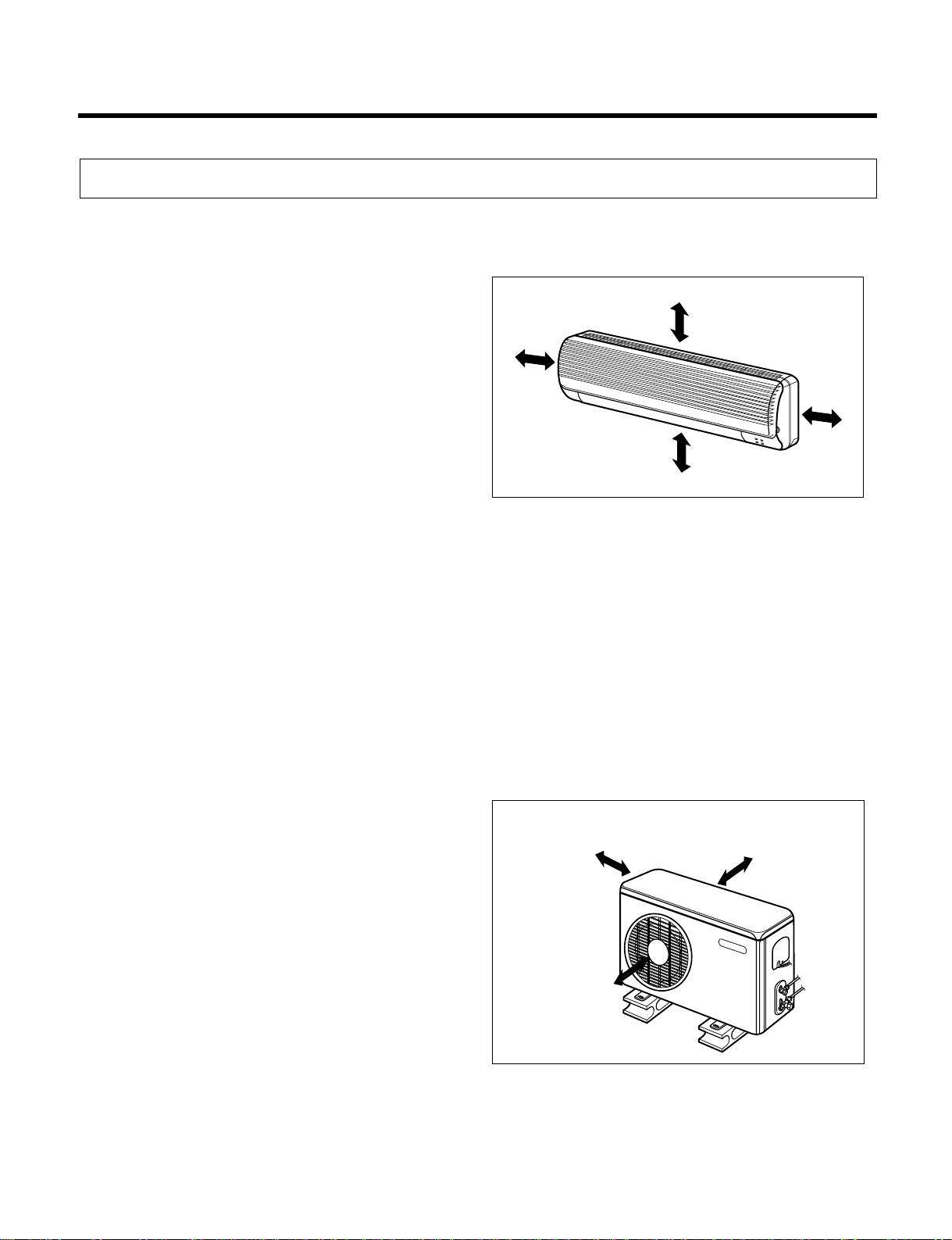
1) Selection of the best location
1. Indoor unit.
2. Outdoor unit.
•
There should not be any heat source or steam near
the unit.
• There should not be any obstacles to prevent the air
circulation.
• A place where air circulation in the room will be good.
• A place where drainage can be easily obtained.
• A place where noise prevention is taken into consid-
eration.
• Do not install the unit near the door way.
• Ensure the spaces indicated by arrows from the wall,
ceiling, fence, or other obstacles.
• If an awning is built over the unit to prevent direct
sunlight or rain exposure, be careful that heat radiation from the condenser is not restricted.
• There should not be any animals or plants which
could be affected by hot air discharged.
• Ensure the spaces indicated by arrows from the wall,
ceiling, fence, or other obstacles.
More than
5 cm
More than 5 cm
More than
5 cm
More than eye-level
More than 10 cm
More than 10 cm
More than 70 cm
- 22 -
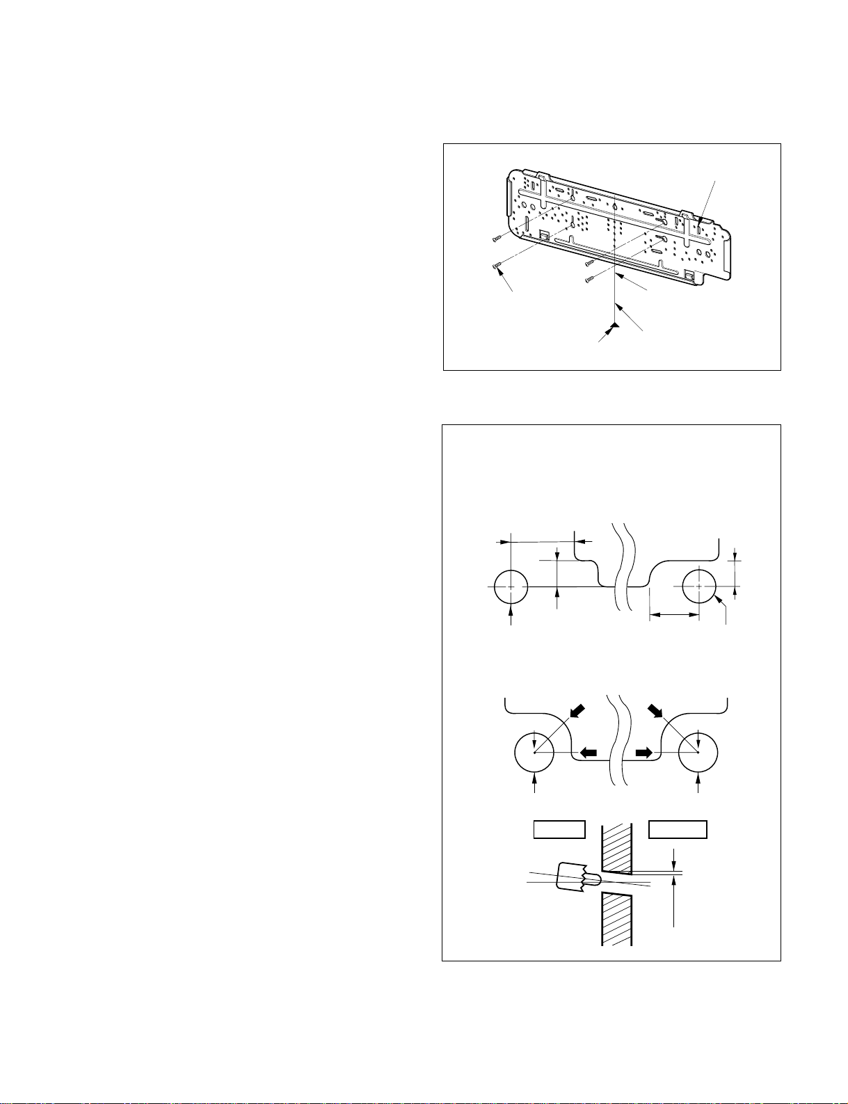
2) Indoor Unit Installation
The mounting wall should be strong and solid enough
to prevent it from the vibration.
1. Mount the installation plate on the wall with
four Type "A" screws.
• Always mount the Installation plate horizontally by
aligning the marking-off line with using the thread
and a level.
2. Drill the piping hole with 70mm dia. holecore
drill.
• Drill the piping hole at either the right or the left and
the hole should be slightly slant to the outdoor side.
Type "A" screw
Installation Plate
marking-off line
Thread
Weight
The lower left and right side of Installation
Plate
Left rear piping
Left rear piping
Right rear piping
Right rear piping
Indoor
Center
Center
<7K, 9K BTU>
<11K, 12K, 14K BTU>
Outdoor
WALL
80mm
20mm
ø70mm
A
50mm
ø70mm
A
20mm
A
A
ø70mm ø70mm
5~7mm
 Loading...