

LG LP096HD3A, LP-153CD3A, LP076CD3A, LP126HD3A, LP153CD5A User Manual

LG Packaged Terminal
Air Conditioner/Heat Pump
SVC MANUAL(Exploded View)
MODEL : LP096HD3A
CAUTION
Before Servicing the unit, read the safety precautions in General SVC manual.
Only for authorized service personnel.
Internal Use Only
http://biz.lgservice.com
- 2 -
Copyright ©2010 LG Electronics. Inc. All right reserved.
Only for training and service purposes
LGE Internal Use Only
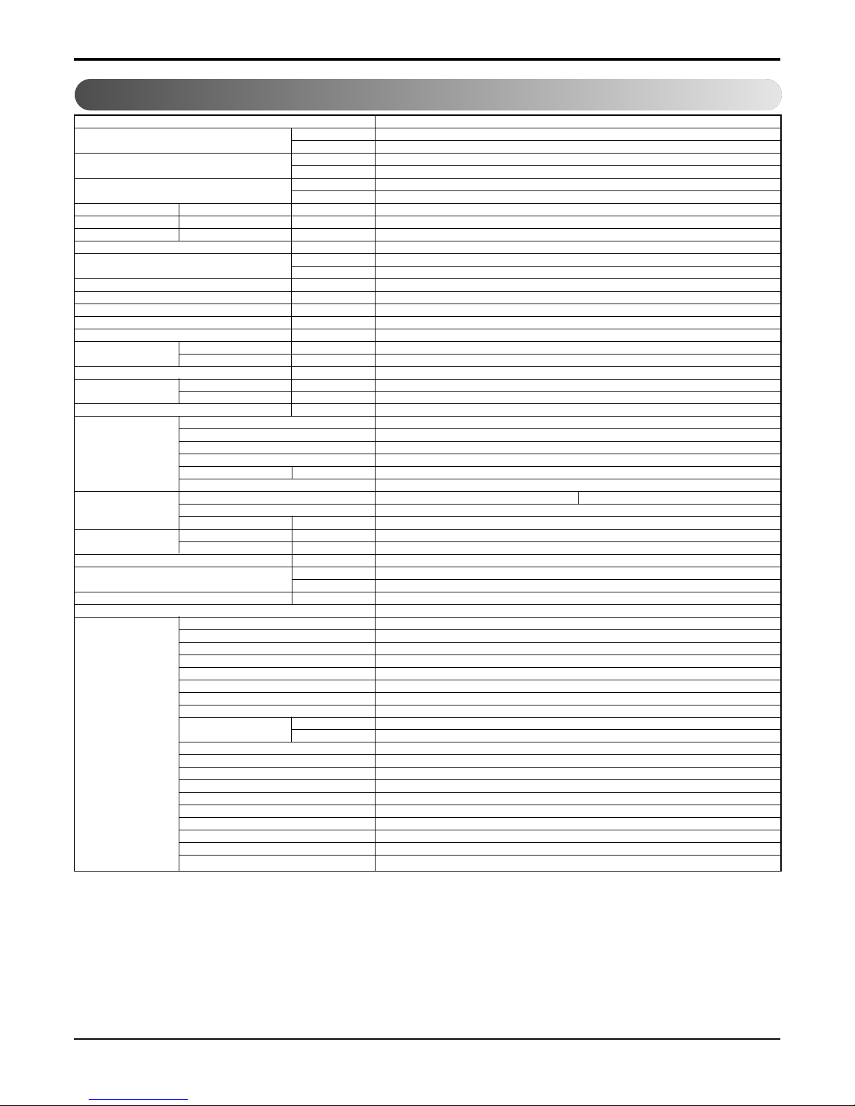
1. Specification
Models
Cooling Capacity kW
Btu/h.
Heating Capacity kW
Btu/h.
Electric Heater capacity kW kW
Btu/h.
Power Input Cooling/Heating W
Running Current Cooling/Heating A
Starting current Cooling/Heating A
Electric Heater Current A
EER W/W
Btu/h.W
COP W/W
Power Supply Ø / V / Hz
Power Factor %
MCA A
MOP A
Air Flow Rate Indoor,Max m3/min(CFM)
Outdoor,Max m3/min(CFM)
Moisture Removal l/h
Sound Level Indoor,H/M/L dB(A)±3
(SOUND PRESSURE,1M)
Outdoor,Max dB(A)±3
Refrigerant & Charge g(oz)
Compressor Type
Model
Motor Type
Oil Type
Oil Charge cc
O.L.P Name
Fan Type(In/Out)
Motor Type(In/Out)
Motor Output(In/Out) W
Heat Exchanger Evaporator Rows*Column*FPI
Condensor Rows*Column*FPI
Power Supply Cable (Power Cord) No.*mm
2
Dimensions ( W * H * D) mm
inch
Net Weight kg(lbs)
Tool Code(Chassis)
Features Temperature Control
Energy Saver Mode
Prefilter(washable/anti-fungus)
Plasma Filter
Steps, Fan/Cool/Heat
Airflow Direction Control(up&down)
Airflow Direction Control(left&right)
Remote Controller Type
Setting Temperature Cooling
Range Heating
Auto Operation (Micom Control)
Panel Touch Type
Timer
Air Discharge
Air-Ventilation
Defrost Control
Hot Start
Look
Cabinet Type(Chassis Type)
Special Function
LP096HD3A
2.67
9,200
2.40
8,200
3.49
11,900
851
3.4/3.0
-
14
3.1
10.8
3.2
1/265/60
95.2/93.2
17.7
20
8.8(310)
20(706)
1
46/-/44
61
R410A,800(28.2)
Rotary
GKS086QAB
PSC
POE(RB68A) or PVE(FVC68D)
330
MRA12060-12026
Cross Flow Fan/Axial Fan
6/4 Poles
11/52
2Rx10Cx19FPI
3Rx17Cx20FPI
3x2.1
1,066x406x505
42x16x19-7/8
46(101.4)
YA
Thermistor
O
O
-
2/2/2
Manual
-
Wall Thermostat
54°F~86°F(12.2°C~30°C)
54°F~86°F(12.2°C~30°C)
-
Micom
12h, On/Off
Rear
O
O
-
L-Look
Slide In-Out
Electric Heater
Note:
O
: Applied, - : No relation
*
For circuit breaker rating, please confirm to local standards wherever necessary.
h
Some of functions are slightly different depending upon models.
h
The specification may be subject to change without prior notice for purpose of improvement.
- 3 -
Copyright ©2010 LG Electronics. Inc. All right reserved.
Only for training and service purposes
LGE Internal Use Only
1.1 FEATURES AND BENEFITS
The PTAC has many features, some of which are different than those found on conventional PTAC units. The servicer must be
familiar with these features in order to properly service the unit.
• IIR (Infinite Impulse Response)
The IIR function senses the temperature several times per second and makes micro-adjustments several times per
• Compressor Restart Delay
This feature extends the overall life of compressor by preventing the short-cycling of the air-conditioner. When the compressor
restarts, LG PTAC is designed to give a minimum of three minutes to have a time of equalizing the refrigerant pressures for
optimizing cycling.
• Fan-Only Setting - High/Low
The fan can run at HIGH or LOW speed without COOLING or HEATING to provide air circulation and ventilation.
• Indoor Fan Speed Selections - High/Low
The fan can run at HIGH or LOW speed for either COOLING or HEATING.
• Two Fan motors
The unit has two fan motors to provide quiet operation and maximum efficiency.
• LED Diagnostics
All units have this feature indicating the problem when the unit is not operating properly with easy-to-read diagnostics. For
example, 1 blink every 2 seconds indicates compressor failure.
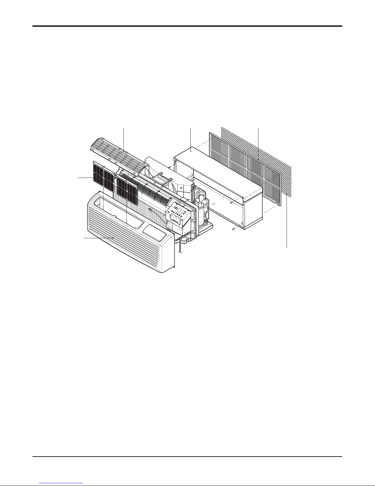
I
N
D
O
O
R
REAR GRILLE
(Aluminum Rear Grille)
EXPANDED METAL GRILLE
(Superior for a performance)
SLEEVE ASSEMBLY
(Including Aluminum Rear Grille)
THE SLEEVE AND THE REAR GRILLE
(Available as an option)
VERTICAL AIR DEFLECTOR
(Horizontal Louver)
AIR FILTER
INLET GRILLE
(Air Intake)

- 4 -
Copyright ©2010 LG Electronics. Inc. All right reserved.
Only for training and service purposes
LGE Internal Use Only
• Indoor Filters
The unit uses two indoor filters which slide in and cut easily. The filters may be cleaned by washing and brushing without
removing the front grille.
• Rotary Compressor
The unit uses a rotary compressor for quiet, reliable operation and long life.
• 2 Position Discharge Grille
The discharge grille can provide air flows upward at an angle of 40 off vertical or 15 degree off vertical. The angle is changed
by removing the front grille and 4 screws that fasten the discharge grille to the front grille and rotating the louvers to an
alternate position.
• Indoor Room Freeze Protection
When the unit senses the room temperature falls to less than 40° F the unit activates the fan motor and either the electric
resistance heater or the hydronic heater to prevent pipes or fixtures from freezing. This also overrides front desk control of the
unit mounted or wall mounted controls.
• Door Switch/Occupancy Sensor
The unit is capable of accommodating a field installed door switch and occupancy sensor to operate the energy management
feature. For additional information, refer to the unit operation section.
• Compressor Overload Protection
This feature prevents the damage of the compressor by sensing the indoor tube temperature in heating. If the indoor
temperature is over 130˚ F, the outdoor fan will be switched off and back on when the temperature drops below 120˚ F.
• Outdoor Air Temperature Switchover
This will effectively change the unit from heat pump mode to total electric resistance heat.
• Temperature limits
The unit is programmed to provide both heating and cooling temperature limits by dip switches on control panel from 50˚ F to
90˚ F. Temperature limits help to prevent overheating and overcooling and reduce energy costs.
• Condensate Drain Valve
The unit has a condensate drain valve to prevent water from collecting or freezing in the basepan.
• Quick Heater Recovery
The unit is designed to operate the electric heater to warm the room to the temperature set point as soon as heat pump cycle
is on in heating. This feature has an advantage of reducing the time to reach the set point and improving the temperature
increase for better comfort.
• Reverse Cycle Defrosting - (PTHP only)
The unit will activate the reverse cycle defrost when the outdoor coil temperature has remained at a cold temperature to form
the ice on the coil.This ice will reduce airflow though the coil and will also reduce the efficiency of unit. The LG PTHP will
employ an active reverse cycle defrost function to melt the ice off the outdoor coil for insuring room comfort conditions and
savings from extended operation.
• High Temperature Heat Pump Operation Protection
The compressor will be switched off to prevent damage when the heat pump is operated in high outdoor temperatures.
• Remote Thermostat Control
Each unit is built to be operated from any standard 4 or 5 wire remote-mounted thermostat, if desired. The unit has a built-in
low voltage power source which can accommodate a large variety of thermostat choices-manual, auto changeover, or
programmable. A remote thermostat can also be added to any installed unit.
• Zone Sensor
Occupants enjoy ultimate comfort with consistent climate control. Attach an optional, inexpensive remote Zone Sensor to
exactly match the functions of the PTAC without disabling any features.
• High Pressure limit
The compressor will be switched off to prevent damage by sensing high pressure [41.8 kgf/cm
2
G, (595 lbf/in2G)] when the unit
is operated in high outdoor temperatures or blocked outdoor inlet.
- 5 -
Copyright ©2010 LG Electronics. Inc. All right reserved.
Only for training and service purposes
LGE Internal Use Only
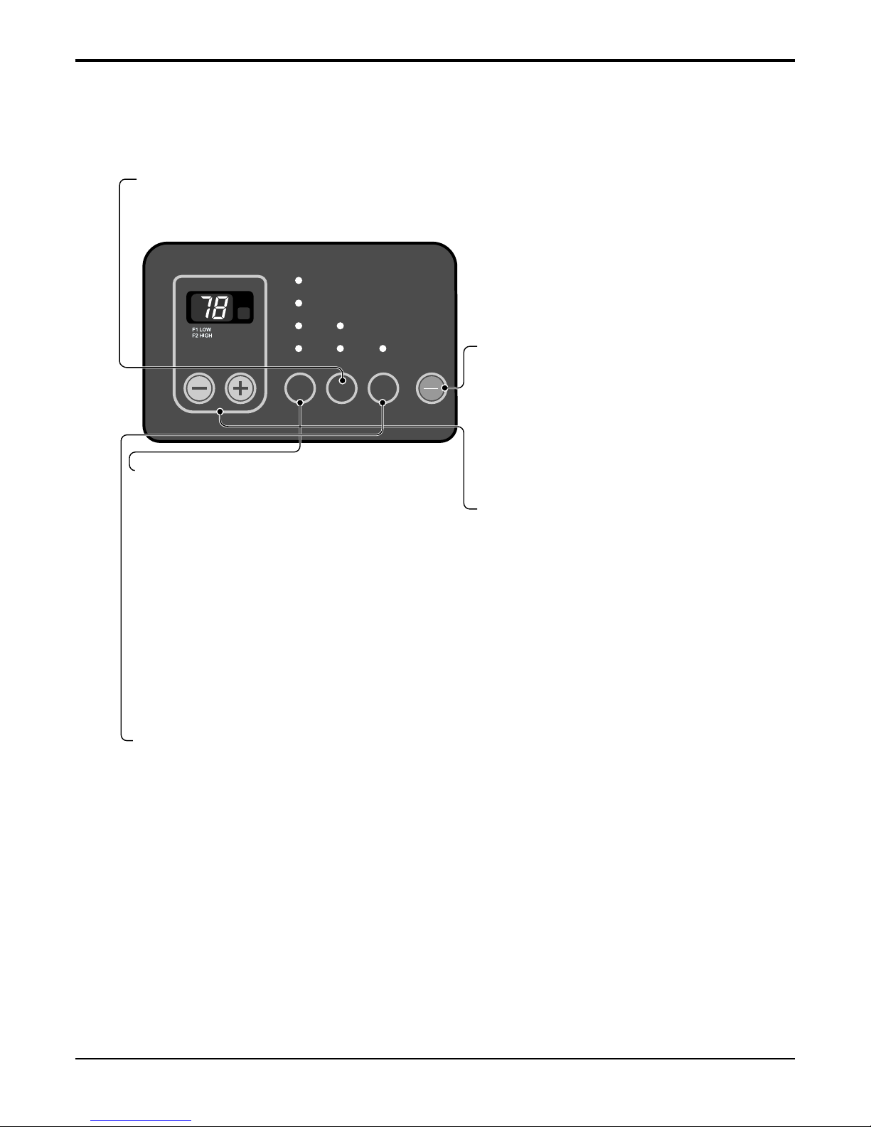
1.2 CONTROL LOCATIONS
• ELECTRONIC CONTROLS
The controls will look like one of the following.
TEMP
MODE
HEAT
E/SAVE
FANFAN
COOLCOOL
HIGHHIGH
LOWLOW TIMERTIMER
FAN TIMER
'
F
ON
OFFONOFF
POWER
MODE
-
Push this button to cycle through the modes from COOL → FAN
→ HEAT→ COOL.
- COOL
• Fan runs continually for normal cooling operation.
- ENERGY SAVER
• The fan stops when the compressor stops cooling.
Approximately every 3 minutes the fan will turn on and the unit
will check the room air temperature to determine if cooling is
needed.
- FAN
• Fan operation without heating or cooling.
- HEAT
• Fan runs continually for normal heating operation.
TIMER
- SHUT-OFF TIME
• You will usually use shut-off time while you sleep.
• If unit is running, use Timer to set number of hours until shut-off.
• For your sleeping comfort, once Time is set, the Temperature setting will raise 2° F after 30 minutes, and once again
after another 30 minutes.
• Push Timer to cycle through the settings from 1 Hour → 2 Hours → ... → 12 Hours maximum.
TEMPERATURE SETTING
• Use this button to automatically control the
temperature of the room.
The temperature can be set within a range of
54° F to 86° F by increments of 2° F.
• The setting appears in the display.
FAN SPEED
• Every time you push this button, it cycles through the settings as follows:
{High(F2) → Low(F1) → High(F2) → Low(F1)}
• To turn the air conditioner ON, push this button.
To turn the air conditioner OFF, push the button
again.
• This button takes priority over any other button.
- 6 -
Copyright ©2010 LG Electronics. Inc. All right reserved.
Only for training and service purposes
LGE Internal Use Only
FUNCTION:
If the unit has a malfunction, a green OPERATION LED located on the Display PCB used by the unit to indicate the
errors.
USE:
If the customer has to register a complaint to the service center, he can be very clear about registering the complaint that
what is happening & by referring the user's manual the customer can clearly define the problem.
So that the engineer should go fully prepared with the prescribed tools to be used regarding that problem. It also keeps
the customer aware about the unit.
Here are some of the problems defined below for which the LED indicates by flashing number of times the error has
been recorded against it.
The errors are the mentioned which is as follows:
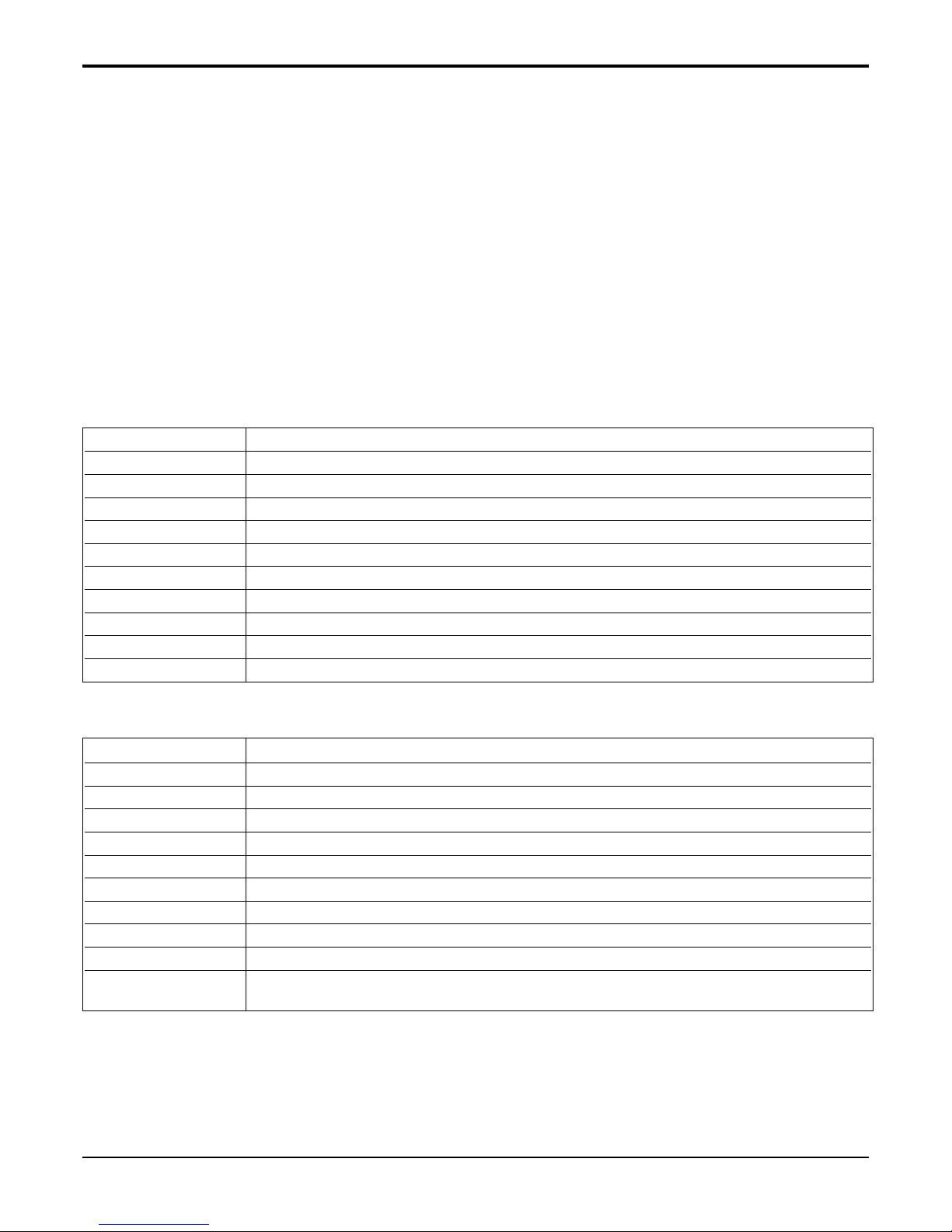
• Electrical Controls
ON Normal
OFF No power / failed board
Fault Codes
CH 01 Indoor Air Thermistor Error
CH 02 Indoor Coil Thermistor Error
CH 03 Outdoor Air Thermistor Error (PTHP Only)
CH 04 Outdoor Coil Thermistor Error (PTHP Only)
CH 05 Mode Error
CH 06 Set point Error
CH 07 Bad Thermistor Wiring
CH 09 Pressure Switch Error
• Manual Controls
ON Normal
OFF No power / failed board
Fault Codes
1 Indoor Air Thermistor Error
2 Indoor Coil Thermistor Error
3 Outdoor Air Thermistor Error (PTHP Only)
4 Outdoor Coil Thermistor Error (PTHP Only)
5 Mode Error
6 Set point Error
7 Bad Thermistor Wiring
LED Flash Rate
0.25 sec On per flash, 0.25 sec OFF between flashes,
2.00 sec OFF between codes.
1.3 SELF-DIAGNOSIS
- 7 -
Copyright ©2010 LG Electronics. Inc. All right reserved.
Only for training and service purposes
LGE Internal Use Only
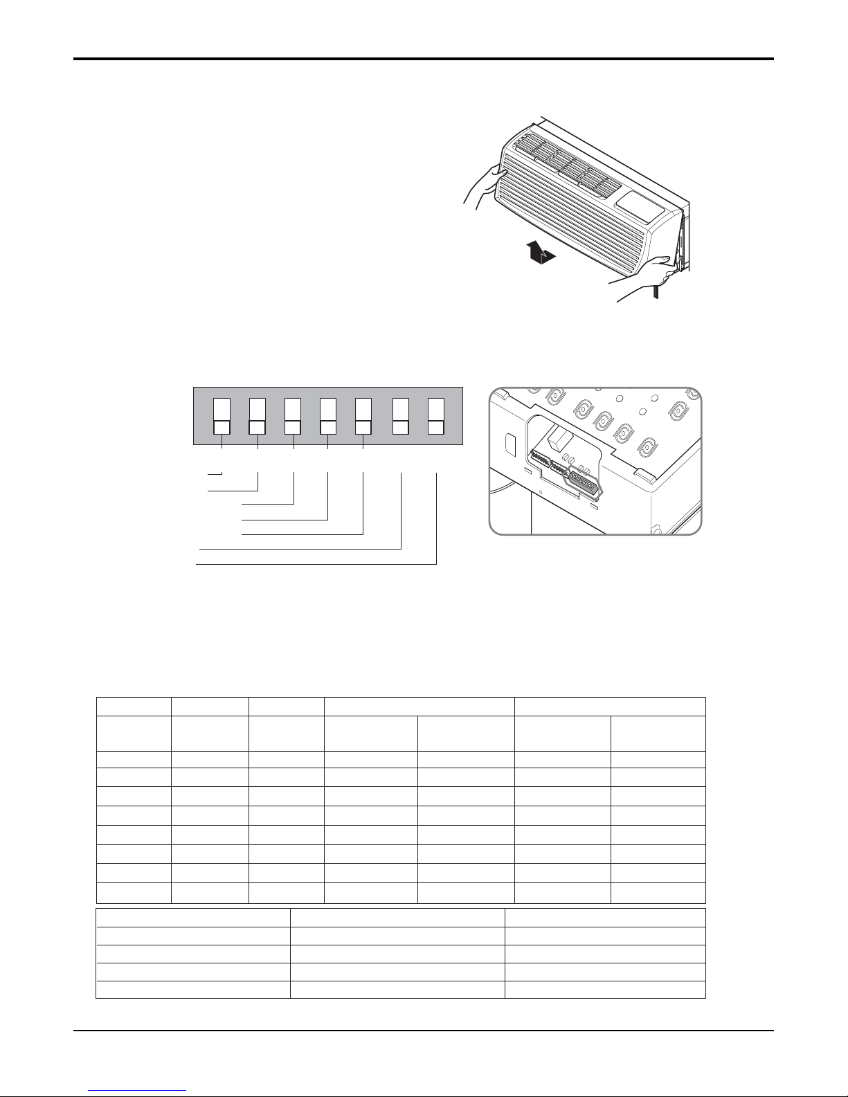
• REMOVING THE FRONT GRILLE
ON
ONREMOTE
OFF
ON ON ON
Remote/Local
Energy Saver
Temperature Limit 1
Temperature Limit 2
Temperature Limit 3
PTAC/PTHP
UNIT TYPE
LOCALLOCAL
1
OFF
OFF
2
OFF
OFF
3
OFF
OFF
4
OFF
OFF
5
LOCAL
1
OFF2OFF3OFF4OFF
5
LOCAL
LOCAL
1
OFF
OFF
2
OFF
OFF
3
OFF
OFF
4
OFF
OFF
5
LOCAL
1
OFF2OFF3OFF4OFF5OFF6OFF
7
LOCALLOCAL
1
OFF
OFF
2
OFF
OFF
3
OFF
OFF
4
OFF
OFF
5
LOCAL
1
OFF2OFF3OFF
4
OFF
5
OFF OFF OFF 54° F (12.2° C) 86° F (30.0° C)
86° F (30.0° C)
86° F (30.0° C)
86° F (30.0° C)
86° F (30.0° C)
86° F (30.0° C)
86° F (30.0° C)
86° F (30.0° C)
54° F (12.2° C)
54° F (12.2° C)
54° F (12.2° C)
54° F (12.2° C)
54° F (12.2° C)
54° F (12.2° C)
54° F (12.2° C)
54° F (12.2° C)
86° F (30.0° C)
ON OFF OFF 56° F (13.3° C)
84° F (28.9° C)
OFF ON OFF 58° F (14.4° C)
82° F (27.8° C)
ON ON OFF 60° F (15.5° C)
80° F (26.7° C)
OFF
OFF ON 62° F (16.6° C)
78° F (25.5° C)
ON OFF ON 64° F (17.7° C)
76° F (24.4° C)
OFF ON ON 66° F (18.9° C) 74° F (23.3° C)
ON ON ON 68° F (20.0° C) 72° F (22.2° C)
Temperature Temperature Temperature
Limit #1 Limit #2 Limit #3
Lowest Temp. Highest Temp. Lowest Temp. Highest Temp.
Cooling Operation#3 #4 #5
Heating Operation
Cooling+Electric Heater+Heat PumpOFFOFF
Cooling+Electric HeaterONOFF
Cooling Only
Heat Pump Only
Unit Type
ON
OFF
#7
ON
ON
#6
1.4 ADDITIONAL CONTROLS
- 8 -
Copyright ©2010 LG Electronics. Inc. All right reserved.
Only for training and service purposes
LGE Internal Use Only
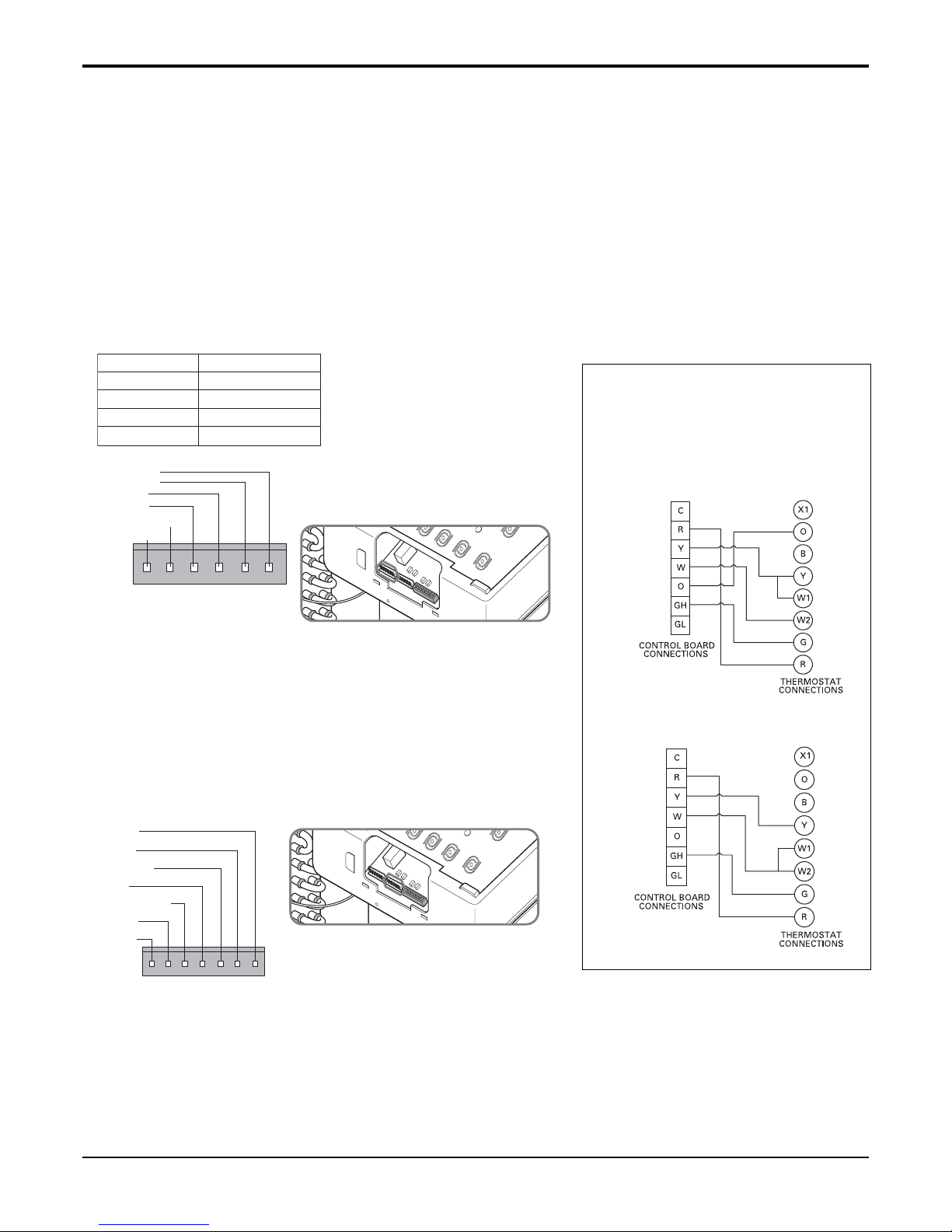
Wiring Schematic for
Remote Heat Pump
Wiring Schematic for
Straight Cool Unit.
• REMOTE/LOCAL CONTROL
When remote/local switch #1 is on, it allow the unit to operate by the Remote Wall Thermostat.
The unit control by knobs are not available.
• ENERGY SAVER
The energy saver switch #2 is on. This switch is set at cycle fan to provide continuous fan operation in cool or heat modes.
When the switch is off the continuous fan allows continuous circulation of room air and make the more balanced temperature
of the room. When the switch is on, the fan is on or off with the compressor or with the heater.
• FRONT DESK CONTROL
When the pair wire is connected to the connector FD2 and FD1, the unit can be turned ON or OFF with a switch located at the
Front Desk Control panel. When the front desk switch is ON, the fan operates according to the setting without working
compressor and heater. When the front desk switch is OFF, the unit can operate according to the setting of controls.
• REMOTE WALL THERMOSTAT
When the wires are connected, the unit will be controlled by a remote wall
thermostat.
The thermostat connections supply the 24 Volt AC. When you install the
digital/electronic thermostat, you must set it to 24 Volt AC. See the
installation Instruction in this manual for the Remote Wall Thermostat.
Note: The following figures show wiring
schematics for heat pump and straight
cool units with electric heat, respectively.
GL GH O W Y R C
Low Fan
High Fan
Reversing Valve
Heater
Compressor
24 Volt-L
24 Volt-N
Wire # AWG Maximum Length
#22 600 ft (180 m)
#20 900 ft (270 m)
#18 1500 ft (450 m)
#16 2000 ft (610 m)
FD2 FD1 DR2 DR1 MS2 MS1
Front Desk Control
Front Desk Control
Door Switch
Door Switch
Motion Sensor
Motion Sensor
(Molex Housing Spec 396-06V)
(Molex Housing Spec 396-07V)
- 9 -
Copyright ©2010 LG Electronics. Inc. All right reserved.
Only for training and service purposes
LGE Internal Use Only
2.1 MECHANICAL PARTS
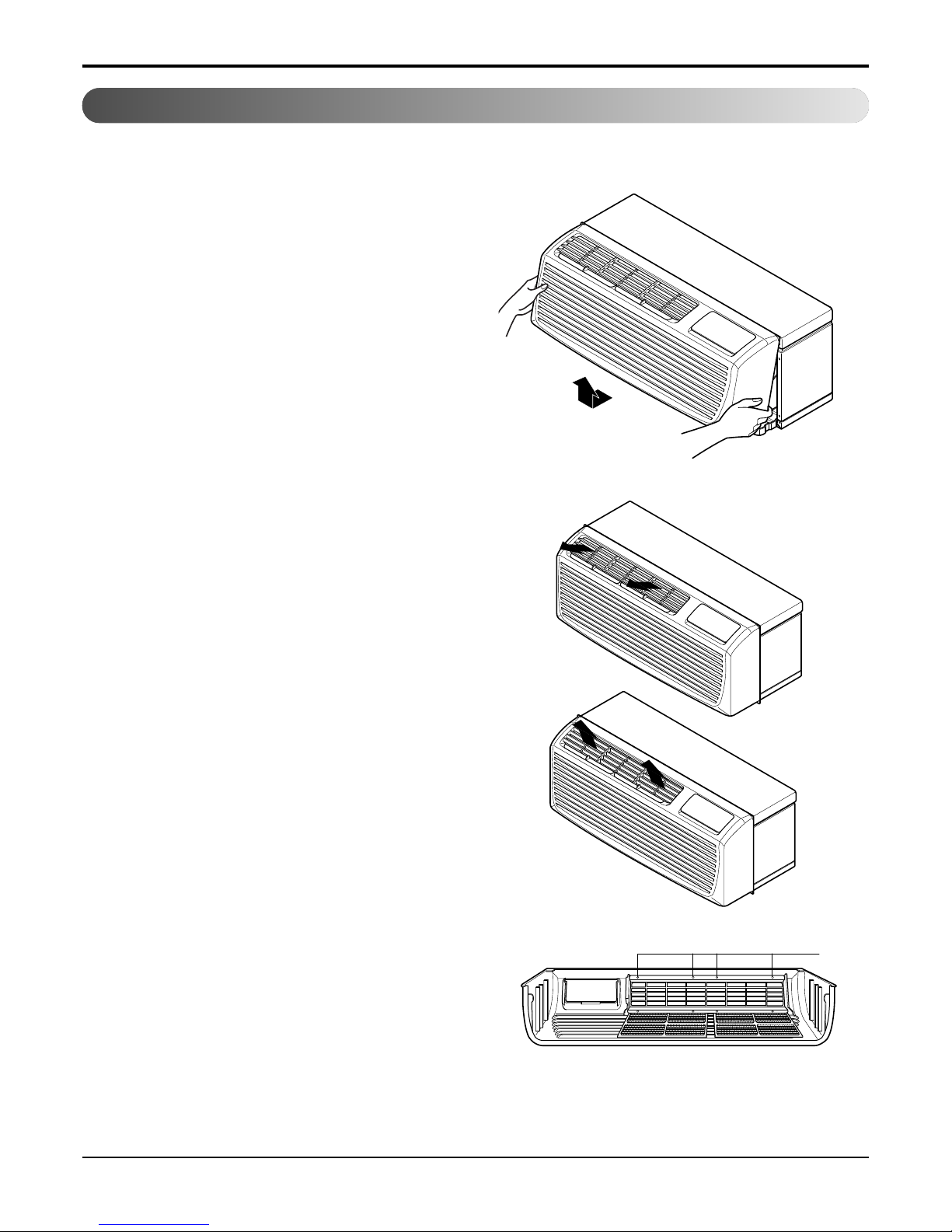
2.1.1 FRONT GRILLE
1. Remove the front grille. (See Figure 1)
2. To remove the front grille, pull out the bottom of
the front grille and then lift up.
Re-install the component by referring to the
removal procedure.
3. To replace the front grille, place the tabs over the
top of the unit and push the bottom of front grille
until the clips snap into place.
• This Room Air Conditioner (PTAC) discharges air
from the top of the unit through reversible, 2-position
discharge grille louvers. The unit is shipped from the
factory with the discharge grille louvers at an angle
of 40˚ off vertical. In the alternate position, the
louvers will be at an angle of 15˚ off vertical.
To adjust air direction, remove the front grille.
Remove the 4 screws that fasten the discharge grille
to the front grille.
Flip the discharge grille 180°, then reattach the
discharge grille to the front grille with 4 screws.
— Before the following disassembly, POWER SWITCH is set to OFF and disconnected the power cord.
Figure 1
40˚
15˚
Screws
2. disassembly instructions
- 10 -
Copyright ©2010 LG Electronics. Inc. All right reserved.
Only for training and service purposes
LGE Internal Use Only
2.1.2 CONTROL BOX
1. Remove the front grille. (Refer to section 2.1.1)
2. Remove the two screws which fasten the control
box. (See Figure 2)
3. Pull the control box from the Air guide.
4. Remove the control box cover. (See Figure 3)
5. Disconnect wire housings on the control box.
6. Pull the control box assembly out from the unit.
(See Figure 4)
7. Re-install the components by referring to the
removal procedure.
Figure 2
Figure 3
Figure 4
- 11 -
Copyright ©2010 LG Electronics. Inc. All right reserved.
Only for training and service purposes
LGE Internal Use Only
Figure 8
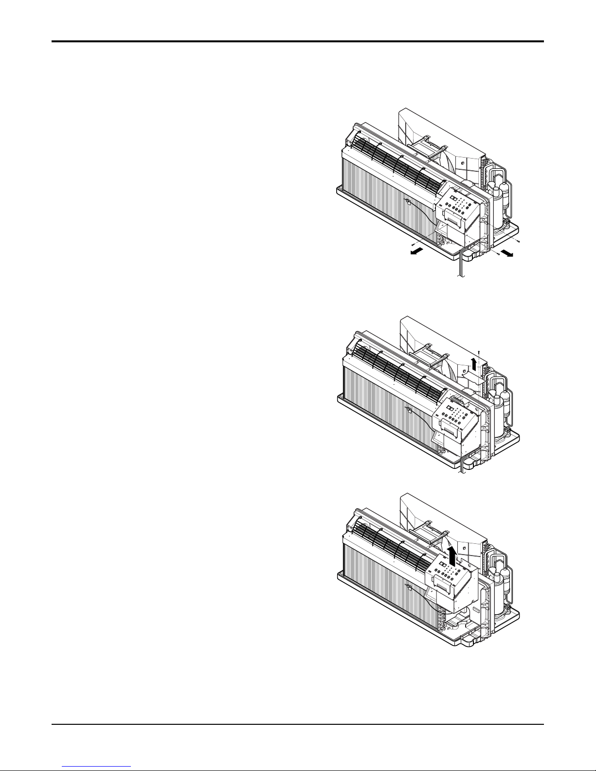
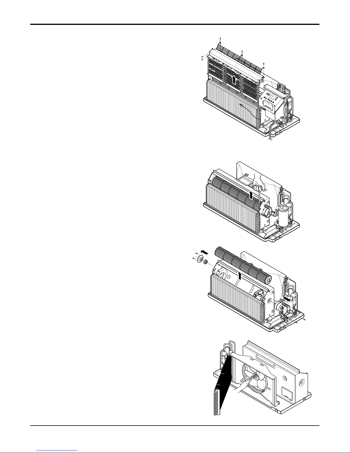
2.2 AIR HANDLING PARTS
2.2.1 HEATER ASSEMBLY AND CROSS
FLOW FAN
1. Remove the front grille. (Refer to section 2.1.1)
2. Remove the control box assembly.
(Refer to section 2.1.3)
3. Remove the 3 screws which fasten the net steel.
(See Fig. 5)
4. Remove the 3 screws which fasten the electric
heater assembly.(Electric heater model only)
(See Fig.5).
5. Loosen the hexagon screw with the Hexwrench(See Fig.6)
6. Remove the 4 screws which fasten the indoor
motor and the earth wire. (See Fig. 6, 7)
7. Re-install the components by referring to the
removal procedure, above.
2.2.2 FAN
1. Remove the brace.
2. Remove the 4 screws which fasten the condenser
with the shroud and the basepan.
3. Move the condenser sideways carefully.
4. Remove the clamp which secures the fan with
plier.
5. Remove the fan. (See Fig. 8)
6. Re-install the components by referring to the
removal procedure, above.
Figure 5
Figure 6
Figure 7
- 12 -
Copyright ©2010 LG Electronics. Inc. All right reserved.
Only for training and service purposes
LGE Internal Use Only
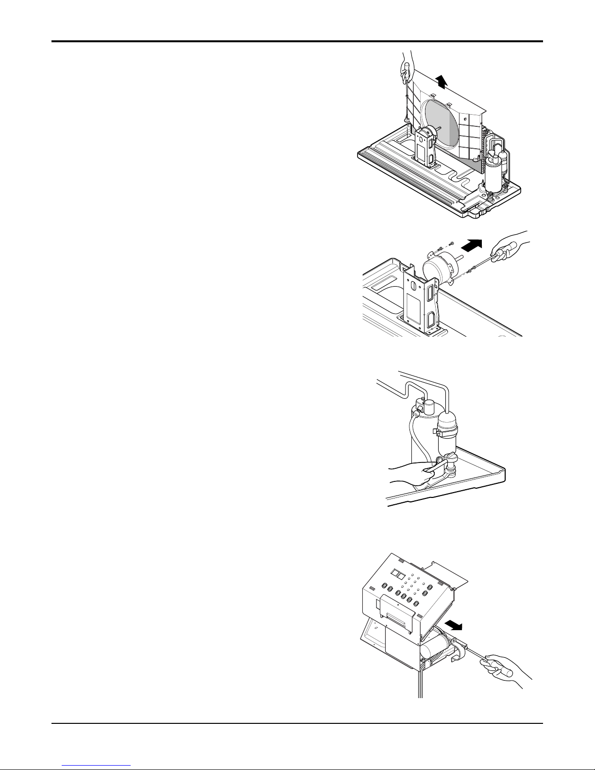
2.2.3 SHROUD
1. Remove the axial fan. (Refer to section 2.2.2)
2. Remove the 4 screws which fasten the condenser
with the shroud and the basepan. (See Figure 9)
3. Remove the shroud.
4. Re-install the component by referring to the
removal procedure.
2.3. ELECTRICAL PARTS
2.3.1 OUTDOOR MOTOR
1. Remove the clamp cord and disconnect a wire
housing in control box. (Refer to section 2.1.2)
2. Remove the axial fan. (Refer to section 2.2.2)
3. Remove the 2 screws which fasten the motor.
(See Figure 10)
4. Remove the motor
5. Re-install the component by referring to the
removal procedure, above.
2.3.2 INDOOR MOTOR (Refer to section 2.2.1)
2.3.3 COMPRESSOR
1. Discharge the refrigerant system using a
refrigerant recovery system.
If there is no valve to attach the recovery system,
install one (such as a WATCO A-1) before venting
the refrigerant. Leave the valve in place after
servicing the system.
2. Disconnect the 3 leads from the compressor.
3. After purging the unit completely, unbraze the
suction and discharge tubes at the compressor
connections.
4. Remove the 3 nuts and the 3 washers which
fasten the compressor. (See Figure 11)
5. Remove the compressor.
6. Re-instill the components by referring to the
removal procedure, above.
2.3.4 CAPACITOR
1. Remove the control box. (Refer to section 2.1.2)
2. Remove 1 screw and disconnect the leads which
connected to the box type capacitor.
(See Figure 12)
3. Remove 1 screw and the clamp which fastens the
can-type capacitor.
4. Disconnect all the leads of capacitor terminals.
5. Re-install the components by referring to the
removal procedure, above.
Figure 9
Figure 10
Figure 11
Figure 12
- 13 -
Copyright ©2010 LG Electronics. Inc. All right reserved.
Only for training and service purposes
LGE Internal Use Only
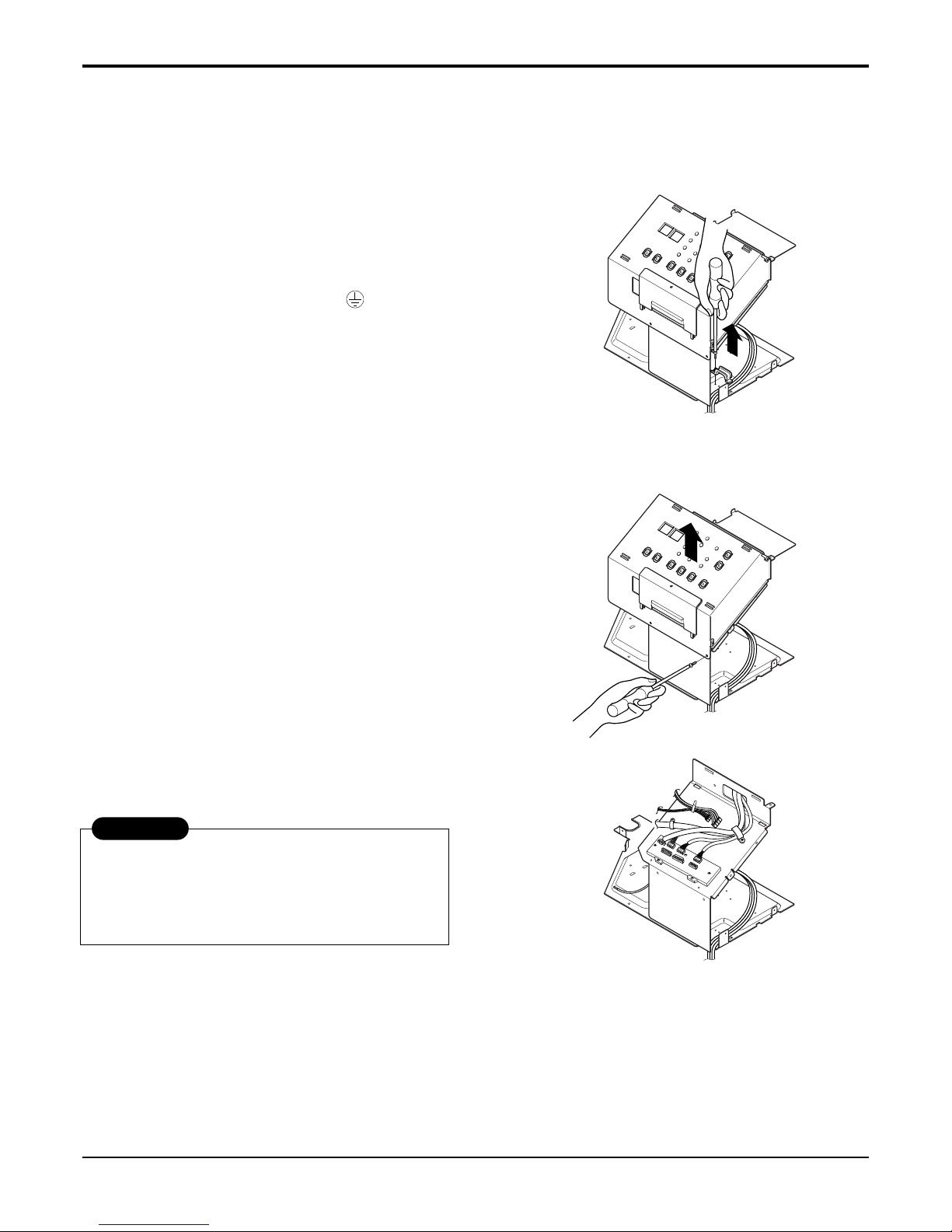
2.3.5 POWER CORD
1. Remove the control box. (Refer to section 2.1.2)
2. Disconnect the grounding screw from the control
box.
3. Disconnect 2 receptacles.
4. Remove a screw which fastens the clip cord.
5. Separate the power cord from the control box.
(See Figure 13)
6. Re-install the component by referring to the
removal procedure, above.
(Use only one ground-marked hole for ground
connection.)
7. If the supply cord of this appliance is damaged, it
must be replaced by an exact replacement part.
(The special cord means the cord which has the
same specification marked on the supply cord
fitted to the unit.)
2.3.6 P.C.B.
1. Remove the all screws which fasten P.C.B. cover.
2. Disconnect all the leads which connected to the
P.C.B.
3. Remove the two screws which fasten the P.C.B.
board.
4. Re-install the components by referring to the
removal procedure, above.
Figure 13
Figure 14
After servicing control box ,make sure that AC and DC
wires are separated and tied up properly.
The wires should also be pressed a little downwards to
prevent touching it to the display pcb.
WARNING
- 14 -
Copyright ©2010 LG Electronics. Inc. All right reserved.
Only for training and service purposes
LGE Internal Use Only
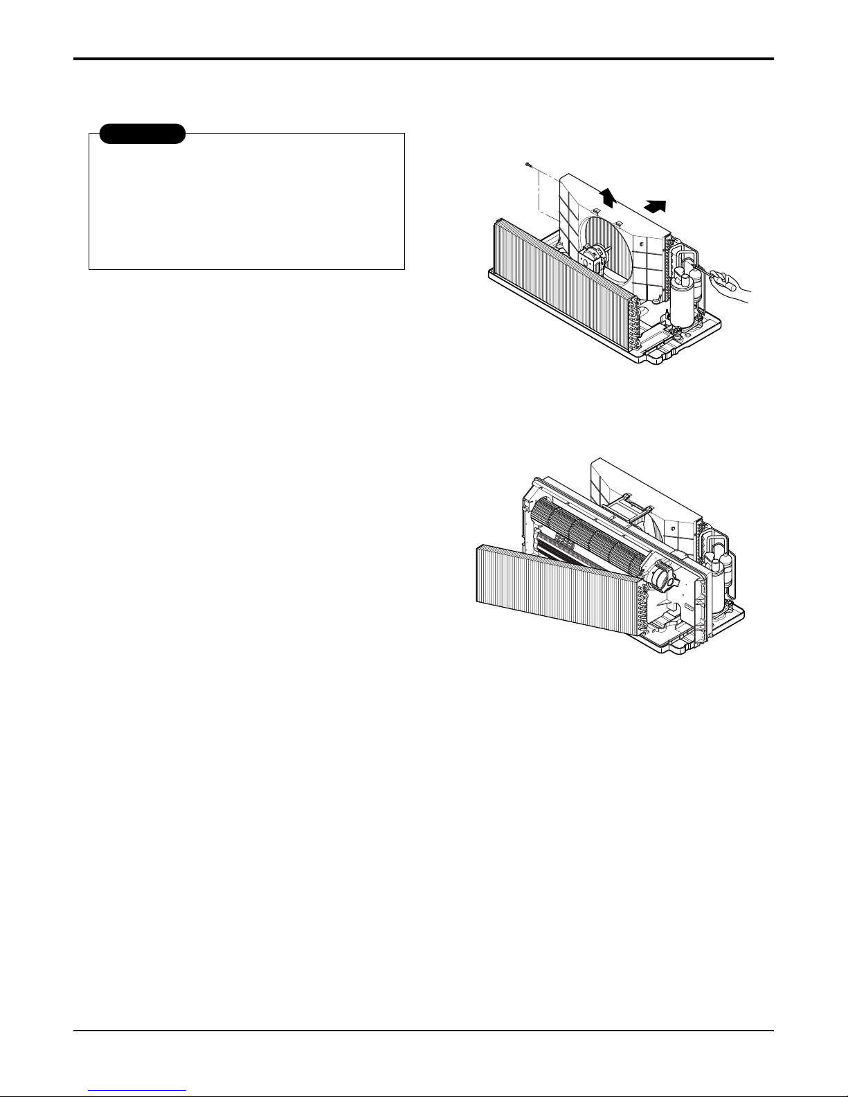
2.4 REFRIGERATION CYCLE
2.4.1 CONDENSER
1. Remove the brace and the shroud.
(Refer to section 2.2.2)
2. Remove the 4 screws which fasten the shroud.
(Refer to section 2.2.2)
3. Push forward the shroud and remove the 2 screws
which fasten the condenser with the basepan.
4. After discharging the refrigerant completely,
unbraze the interconnecting tube at the condenser
connections.
5. Remove the condenser.
6. Re-install the components by referring to notes.
(See Figure 15)
2.4.2 EVAPORATOR
1. Remove the front grille. (Refer to section 2.1.1)
2. Discharge the refrigerant completely.
3. Remove the control box assembly.
(Refer to section 2.1.2)
4. Remove the 4 screws which fasten the evaporator
at the left side and the right side.
5. Move the evaporator sideward carefully and then
unbraze the interconnecting tube at the evaporator
connectors.
6. Remove the evaporator.
7. Re-install the components by referring to notes.
(See Figure 16)
2.4.3 CAPILLARY TUBE
1. After discharging the refrigerant completely,
unbraze the interconnecting tube at the capillary
tube.
2. Remove the capillary tube.
3. Re-install the components by referring to notes.
Figure 15
Discharge the refrigerant system using a
refrigerant recovery system.
If there is no valve to attach the recovery system,
install one (such as a WATCO A-1) before
venting the refrigerant. Leave the valve in place
after servicing the system.
CAUTION
Figure 16
- 15 -
Copyright ©2010 LG Electronics. Inc. All right reserved.
Only for training and service purposes
LGE Internal Use Only
— Replacement of the refrigeration cycle.
1. When replacing the refrigeration cycle, be sure to
discharge the refrigerant system using a
refrigerant recovery system.
If there is no valve to attach the recovery system,
install one (such as a WATCO A-1) before venting
the refrigerant. Leave the valve in place after
servicing the system.
2. After discharging the unit completely, remove the
desired component, and unbraze the pinch-off
tubes.
3. Solder service valves into the pinch-off tube ports,
leaving the valves open.
4. Solder the pinch-off tubes with service valves.
5. Evacuate as follows.
1) Connect the vacuum pump, as illustrated
Figure 16 A.
2) Start the vacuum pump, slowly open manifold
valves A and B with two full turns
counterclockwise and leave the valves closed.
The vacuum pump is now pulling through valves
A and B up to valve C by means of the manifold
and entire system.
3) Operate the vacuum pump for 20 to 30 minutes,
until 600 microns of vacuum are obtained. Close
valves A and B, and observe the vacuum gauge
for a few minutes. A rise in pressure would
indicate a possible leak or moisture remaining in
the system. With valves A and B closed, stop
the vacuum pump.
4)
Remove the hose from the vacuum pump and
place it on the charging cylinder. See Figure 16 B.
Open valve C.
Discharge the line at the manifold connection.
5) The system is now ready for final charging.
6. Recharge as follows :
1) Refrigeration cycle systems are charged from the
high-side. If the total charge cannot be put
in the high-side, the balance will be put in the
suction line through the access valve which you
installed as the system was opened.
2)
Connect the charging cylinder as shown in Figure
16B.
With valve C open, discharge the hose at the
manifold connection.
3) Open valve A and allow the proper charge to
enter the system. Valve B is still closed.
4) If more charge is required, the high-side will not
take it. Close valve A.
5) With the unit running, open valve B and add the
balance of the charge.
a. Do not add the liquid refrigerant to the low-
side.
b. Watch the low-side gauge; The Pressure of
optimum condition is as below.(Cooling)
c. Turn off valve B and allow pressure to drop.
d. Repeat steps B and C until the balance of the
charge is in the system.
6) When satisfied the unit is operating correctly,
use the pinch-off tool with the unit still running
and clamp on to the pinch-off tube. Using a tube
cutter, cut the pinch-off tube about 2 inches from
the pinch-off tool. Use sil-fos solder and solder
pinch-off tube closed. Turn off the unit, allow it to
set for a while, and then test the leakage of the
pinch-off connection.
NOTES
If high vacuum equipment is used, just crack
valves A and B for a few minutes, then open
slowly with the two full turns counterclockwise.
This will keep oil from foaming and being
drawn into the vacuum pump.
CAUTION
OUTSIDE TEMPERATURE THE PRESSURE OF LOW-SIDE GAUGE
35°C(95°F) 8.8kgf/cm2G
(124.5 lbf/in2G)
 Loading...