

LG Low Ambient Control Kit, PRVC2 Installation Manual

P/NO : MFL42540228
www.lg.com
INSTALLATION MANUAL
• Please read this installation manual completely before installing the product.
• Installation work must be performed in accordance with the national wiring
standards by authorized personnel only.
• Please retain this installation manual for future reference after reading it
thoroughly.
❈ PRVC2 is available only for the Multi-V IV model
(PRVC2 can not be installed for the previous Multi-V IV model)
MODEL : PRVC2
Low Ambient Control Kit

Low Ambient Control Kit Installation manual
TABLE OF CONTENTS
■ Safety Precautions................................................................................3
■ Accessory Parts....................................................................................6
■ Name of each Part................................................................................7
■ Installation Method................................................................................8
1. IO Module Installation Method..........................................................8
2. Transformer, Terminal Block Installation Method............................10
■ Setting and Using Method ..................................................................12
1. Wiring Diagram ..............................................................................12
2. Power Source Input .......................................................................13
3. IO Module - Low Ambient Kit Function...........................................15
4. IO Module – Other Function ...........................................................16
5. Wiring for Damper Actuator............................................................19
6. Setting of Outdoor Unit Dip Switch.................................................22
■ Installation Method of Snow Hood and Air Damper ...........................23
1. One Unit with Snow Hood and Air Damper ...................................23
2. Two and Three Units with Snow Hood and Air Damper ................24
3. Unit Placement and Clearances.....................................................25
2 Low Ambient Control Kit
Safety Precautions
To prevent injury to the user or other people and property damage, the following instructions
must be followed.
■ Incorrect operation due to ignoring instruction will cause harm or damage. The seriousness is
classified by the following indications.
■ Meanings of symbols used in this manual are as shown below.
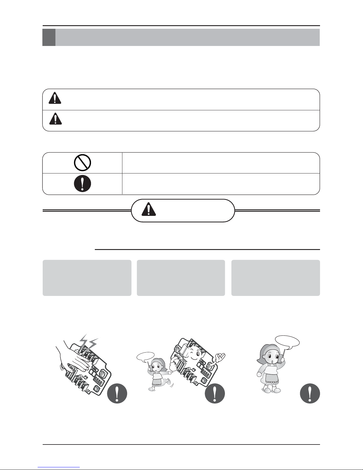
WARNING
CAUTION
This symbol indicates the possibility of death or serious injury.
This symbol indicates the possibility of injury or damage.
Be sure not to do.
Be sure to follow the instruction.
WARNING
Installation manual 3
Safety Precautions
■ Installation
Service
Center
Service
Center
Don’t touch with the hands
while the power is on.
• Cause fire, electric shock,
explosion or injury.
Product installation must
be referred to a service
center or installation shop.
• Cause fire, electric shock,
explosion or injury.
Request installation from
installation shop or service
center when reinstalling
the product.
• Cause fire, electric shock,
explosion or injury.
4 Low Ambient Control Kit
Safety Precautions
Standardized
product
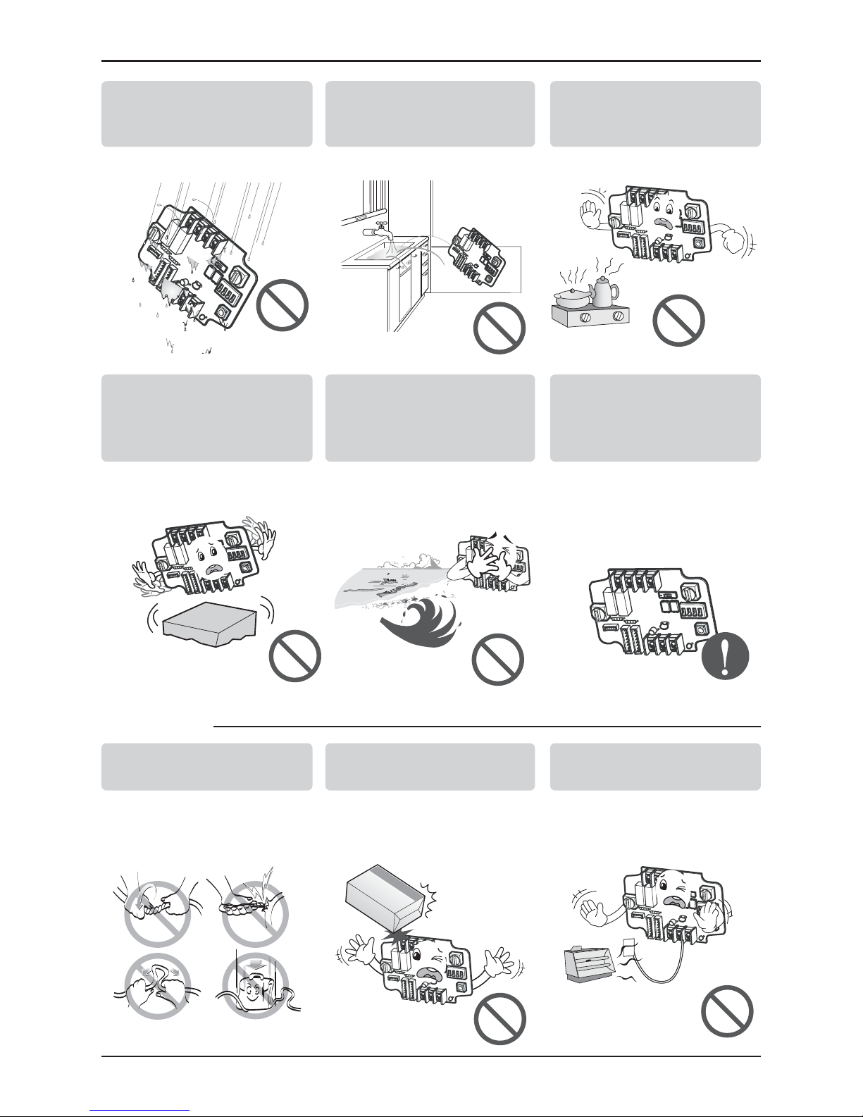
Do not install the product
in the place where rain can
get to the product.
• Cause product failure
Do not install the unit in
humid locations.
• Cause product failure
Do not put the product
closer to fire.
• Cause fire
Do not install in a place
that cannot withstand the
weight of the product.
• The product may get
damaged or may break.
Do not install the product
to a place that generates
oil, steam, salt, sulfuric
gas, etc.
• Cause the product’s
deformation or failure.
Use standardized Product.
• Cause product failure
Do not change or extend
power lines arbitrarily.
• Cause fire or electric shock.
Do not give a shock to the
product.
• If you give a shock to the
product, it may cause the
product’s failure.
Do not use a heater near
the power line.
• Cause fire or electric shock.
■ Operation
Safety Precautions
Installation manual 5
Service
Center
STOP
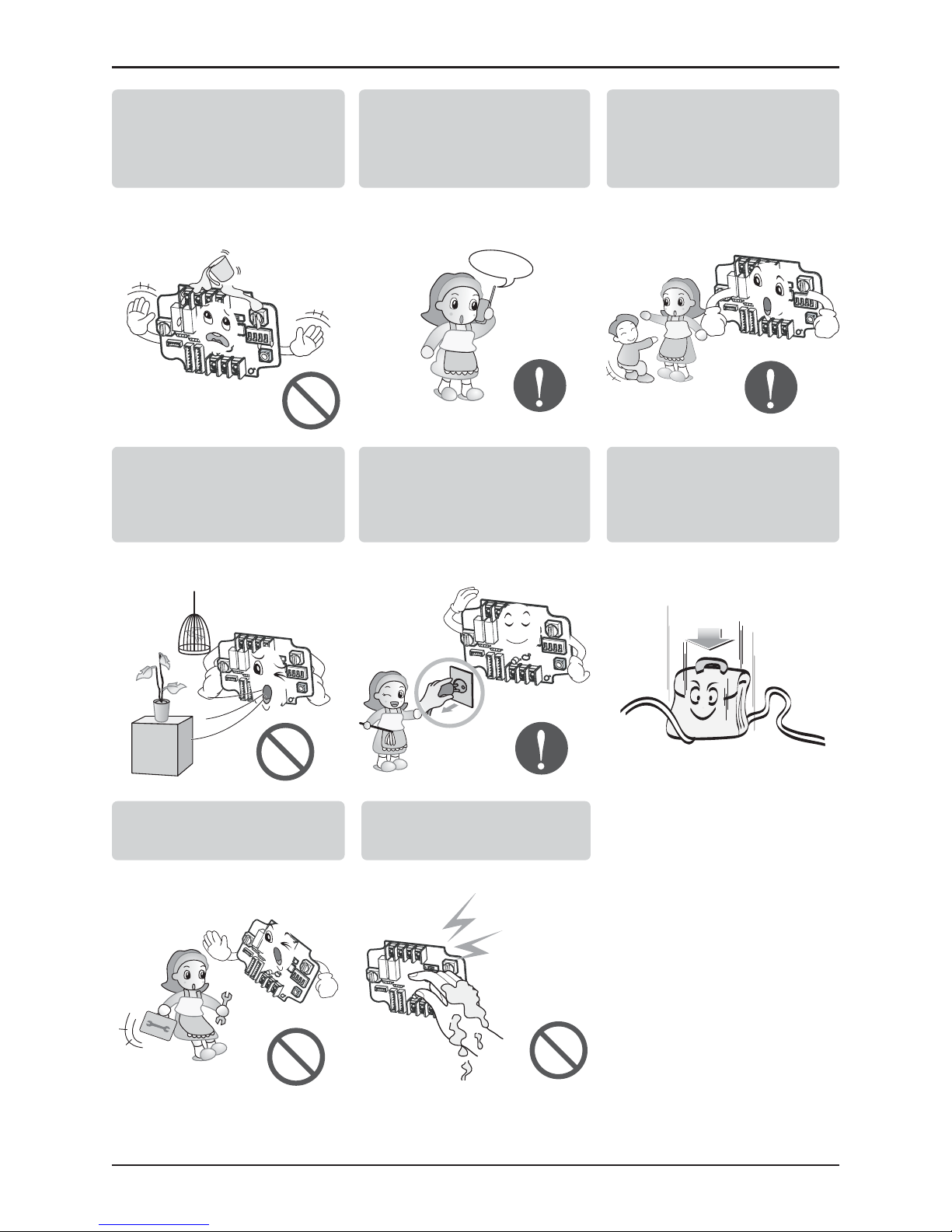
Do notspill water inside of
the product.
• Cause electric shock or
breakdown.
If the product has been
inundated, you must refer to
a service center or
installation shop.
• It can cause a fire.
Children and elderly use the
product under the
guardian’s supervision.
• Cause accidents and product
failures.
Do not use for special
purpose / place such as
conserving flora and fauna,
precision instruments, art.
• Otherwise, it can cause property
damage.
Remove the power plug
when cleaning.
• Cause fire or electric shock.
Do not place heavy objects
on the power line.
• Cause fire or electric shock.
Do not disassemble, repair,
or modify the product.
• Cause fire or electric shock.
Do not touch with wet
hands.
• Cause fire or electric shock.
Accessory Parts
6 Low Ambient Control Kit
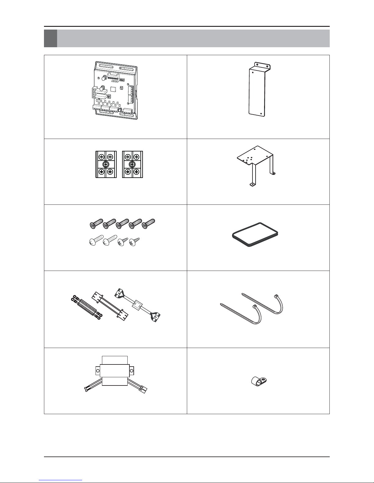
Accessory Parts
IO Module
Bracket 1
Terminal Block (2EA)
Bracket 2
Screw (9EA)
Manual
Cable (3EA)
Tie (2EA)
Transformer
Clamp
Name of each Part
Installation manual 7
ڸ
ڹ
ں
ڻ
ڼڽ
ۀ
ڿ
ھ
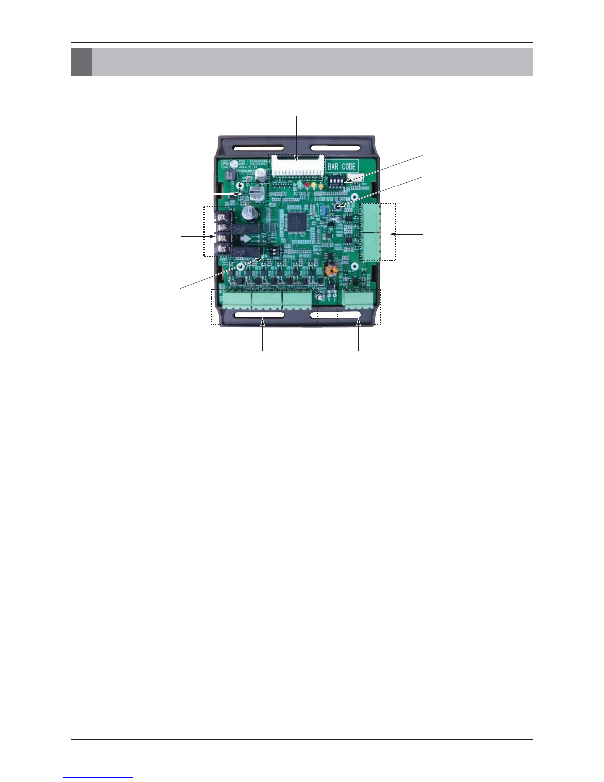
Name of each Part
① Main connector : Power input and communication connector with Outdoor unit
② SW104 : Rotary Switch for setting Demand control step
③ Digital Output : Operating & Error status Relay output (250V, 1A)
④ SW102 : Switch for setting internal function
⑤ Digital Input : Dry contact input
⑥ Analog Input : DC0~10V Analog signal input
⑦ Analog Output : DC0~10V Analog signal output
⑧ SW103 : Reset Switch
⑨ SW101 : Dip Switch for setting operating function

Installation Method
8 Low Ambient Control Kit
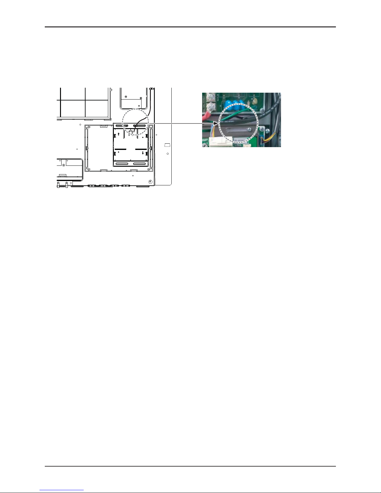
1. IO Module Installation Method
Installation Method
① Separate front panel from outdoor unit.
② Separate front cover of control box.
③ Assemble IO Module and bracket.
④
Connect the connection wires according to the instructions. (Please refer to Setting and Using Method)
ڸ
ڹ
ں
+
ڻ
Main board connector
CAUTION
Be sure to turn off outdoor unit power before installation.
Installation Method
Installation manual 9
⑤ Fix and fasten components and cables.
⑥ Perform the switch setting according to the instructions.
 Loading...