

Page 1

OWNER’S MANUAL
Network
Camera
Please read this manual carefully before operating your set and
retain it for future reference.
MODELS
LNV7260R
LNV5460R
LNU7260R
LNU5460R
*MFL69716701*
1610 (V1.0)
Page 2

Contents
Introduction ......................................................................................3
Features Chart.................................................................................................... 3
Operation and settings .....................................................................4
Before using the system ............................................................................... 4
Recommended PC Requirements .............................................................4
Accessing the LG IP device ........................................................................... 5
LG Smart Web Viewer Overview .............................................................. 6
Live View ........................................................................................................................6
System Settings .....................................................................................................8
Playback ................................................................................................................. 9
Search recording les ........................................................................................9
Download recording les ................................................................................9
Playback ..........................................................................................................................9
Recording snapshot .............................................................................................9
Video clip ........................................................................................................................9
Four screen play ..................................................................................................10
Full screen .................................................................................................................10
Switch mode .......................................................................................................... 10
Log searching ................................................................................................... 11
Conguring the LG Network Camera Device .................................. 12
Accessing the Conguration menu .................................................12
Conguration ................................................................................................... 12
Conguration menu overview...............................................................12
Audio video set .................................................................................................... 13
Camera set...............................................................................................................15
VCA ................................................................................................................................. 17
OSD ................................................................................................................................. 21
Storage Management ...................................................................................21
Network Management ................................................................................ 23
User management ............................................................................................ 25
Alarm Management ........................................................................................ 26
Mask Alarm ............................................................................................................. 27
PTZ Management .............................................................................................27
Advance Set ............................................................................................................28
Reference ........................................................................................30
Troubleshooting .............................................................................................. 30
Open Source Software Notice Information ......................................32
Specications ................................................................................................... 33
2
Page 3

Introduction
The LG Network Camera is designed to use on an Ethernet network and must be assigned an IP address to make it accessible.
This manual contains instructions on how to install and manage the LG Network Camera in your networking environment. Some knowledge of
networking environments would be beneficial to the reader.
Note that design and specification of this unit may change from the manual as quality and improvement without prior notice.
Should you require any technical assistance, please contact authorized service center.
Features Chart
This table shows the differences between the models.
Item RS-485 Zoom Focus External Day/Night
LNV7260R Yes Yes Auto Focus Yes
LNV5460R Yes Yes Auto Focus Yes
LNU7260R Yes Yes Auto Focus Yes
LNU5460R Yes Yes Auto Focus Yes
Introduction 3
Page 4

Operation and settings
Before using the system
• LG IP device recommended to use in the closed network for network
security.
• Before using the LG IP device make sure the connections are correct
and verify whether proper power supply is used.
• Check the connections of the LG IP device for the correct conditions.
• Check that the LG IP device is(are) connected to the network and
that power is supplied.
• Once the connections are made you need to install the LG client
program to the PC from which you want to access the device.
The LG Smart Web Viewer program is automatically installed when
you connect the LG IP device.
The LVi510 and the LG Smart Web Viewer program are the network
program of the LG Video Server and the LG IP cameras.
• To view streaming video in Internet Explorer, set your browser
to allow ActiveX controls. If you find this message “Click here to
download the plug in, close all explorers during the installaion.”, Click
the blue bar and install LG Smart Web Viewer Program on your
computer. Please set your browser zoom level to 100 %.
• The Layouts and the Live view pages may differ with different OS
(Operating Systems) and Web Browsers.
• Care needs to be taken not to run any other applications when the
Client Program is running as it may cause memory shortage.
• When you set on 60 fps in mobile applications, may be degraded the
frame rate depending on mobile performance.
Recommended PC Requirements
The LG IP device can be used with most standard operating systems and
browsers.
Items Requirements
Operating System
CPU Intel i7 or above
Web Browser IE9 or above
DirectX 10.X or above
Memory 4 GB or above
Graphics Card 512 MB or above
Hard Disk 250 GB or above
Resolution 1920 x 1280 or above
Note:
For Windows 7, please download & install ‘DirectX End-User Runtime
Web Installer’.
“http://www.microsoft.com/en-us/download/details.aspx?id=35”
Windows XP Professional,
Windows 7 or above
4 Operation and settings
Page 5

Accessing the LG IP device
You can access the LG IP device by following the below steps.
1. Install LVi510 Program
It recommended to use LVi510 surely.
Otherwise, it is required to install the IP Utility
[Package>Tools>LG IP Utility Installer] to search the IP addresses
of LG IP devices.
2. Discover the LG IP device using the IP Utility
The IP Utility can automatically discover and display LG IP devices on
your network.
The IP Utility shows the MAC address, IP address, Model name and
so on.
Note:
The computer running the IP Utility must be on the same network
segment (physical subnet) as the LG IP device.
2.1 Run the IP Utility program.
2.2 Click the [Search] button or select the [Search] option in the
Device search menu.
After a few seconds the found LG IP devices gets displayed in
the IP Utility window.
3. Logging in to the LG Smart Web Viewer
3.1 Run the IP Utility and find the LG IP devices.
3.2 When the LG IP devices appear in the IP Utility window,
double-click IP address or right click on the same IP address
and select “Connect to Web Page” to start the LG Smart
Web Viewer. When accessing the LG Smart Web Viewer, the
window for login will be shown. Select the language in dropdown list on right top of the window.
3.3 Enter the user name and password. (Note that the default
administrator user name and password are “admin”.)
Note:
Default password must be changed for security after initial
connection.
Note:
• You can also access the LG Smart Web Viewer as shown
below.
3.1 Start your Web browser.
3.2 Enter the IP address of the LG IP device in the address
bar of the browse.
3.3 Enter the user name and password set by the
administrator.
• Check the browser cookies settings to use the
[Remember my credentials].
• If LG Smart Web Viewer is required to be updated, it needs
more time to display according to the network conditions.
• If you connect the LG Smart Web Viewer for the first time,
the Security Warning window is displayed to install the LG
Smart Web Viewer program. You must install the LG Smart
Web Viewer program for using the LG IP device.
• If your computer or network is protected by a proxy or
firewall, the proxy or firewall settings can prevent the LG
Smart Web Viewer program. Change the proxy or firewall
settings to activate the LG Smart Web Viewer program.
• Please use IE browser of windows and make sure the version
above 9.0. Do not use any other browser except Firefox,
Google.
Operation and settings 5
Page 6
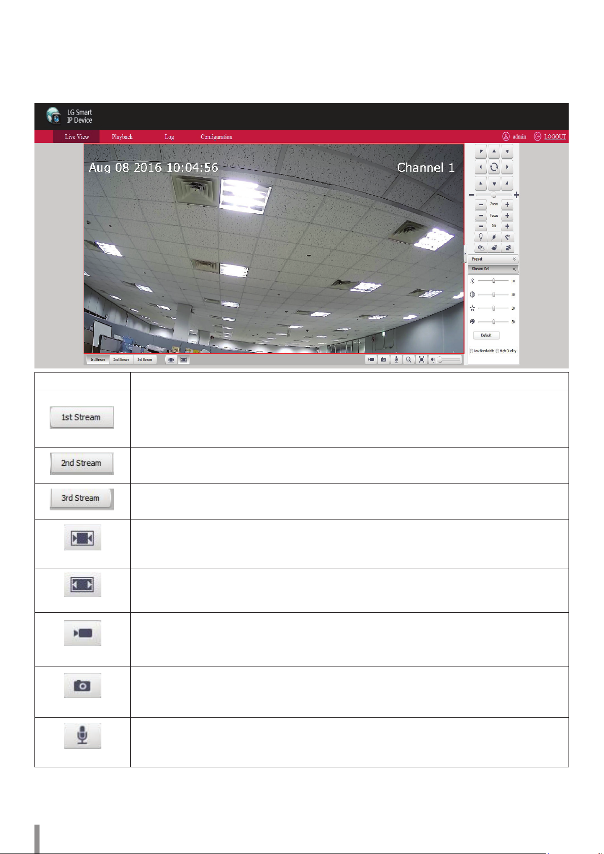
LG Smart Web Viewer Overview
Live View
Item Description
Preview the first stream video (Default display).
Note:
You can set the stream configurations independently. This would facilitate the user to set the live view at user’s comfort.
Previews the second stream video.
Previews the third stream video.
Fixed proportion of video images according to the resolution of the IPC.
Original Aspect Ratio
Displays video images to fit windows.
Fit window
Click this button, video is recorded automatically. To stop the recording, click this button again during the recording.
Default save path is:
Local record
D:\NetVideoBrowser\ RecordFiles
Click this button, current image is saved automatically to JPEG format on your computer.
Default save path is:
Snapshot
Talkback
D:\NetVideoBrowser\ CapturePics
Click this button to start intercom. To stop intercom, click this button again.
6 Operation and settings
Page 7

Open Audio
Set mute
Full screen
Adjust audio volume of the speaker on the computer. Click the speaker icon to switch the sound on or off.
When you want to switch the sound off, click this speaker icon.
Click this button to enter the full screen. Double click the screen or press [Esc] button of keyboard to quit.
Operation and settings 7
Page 8
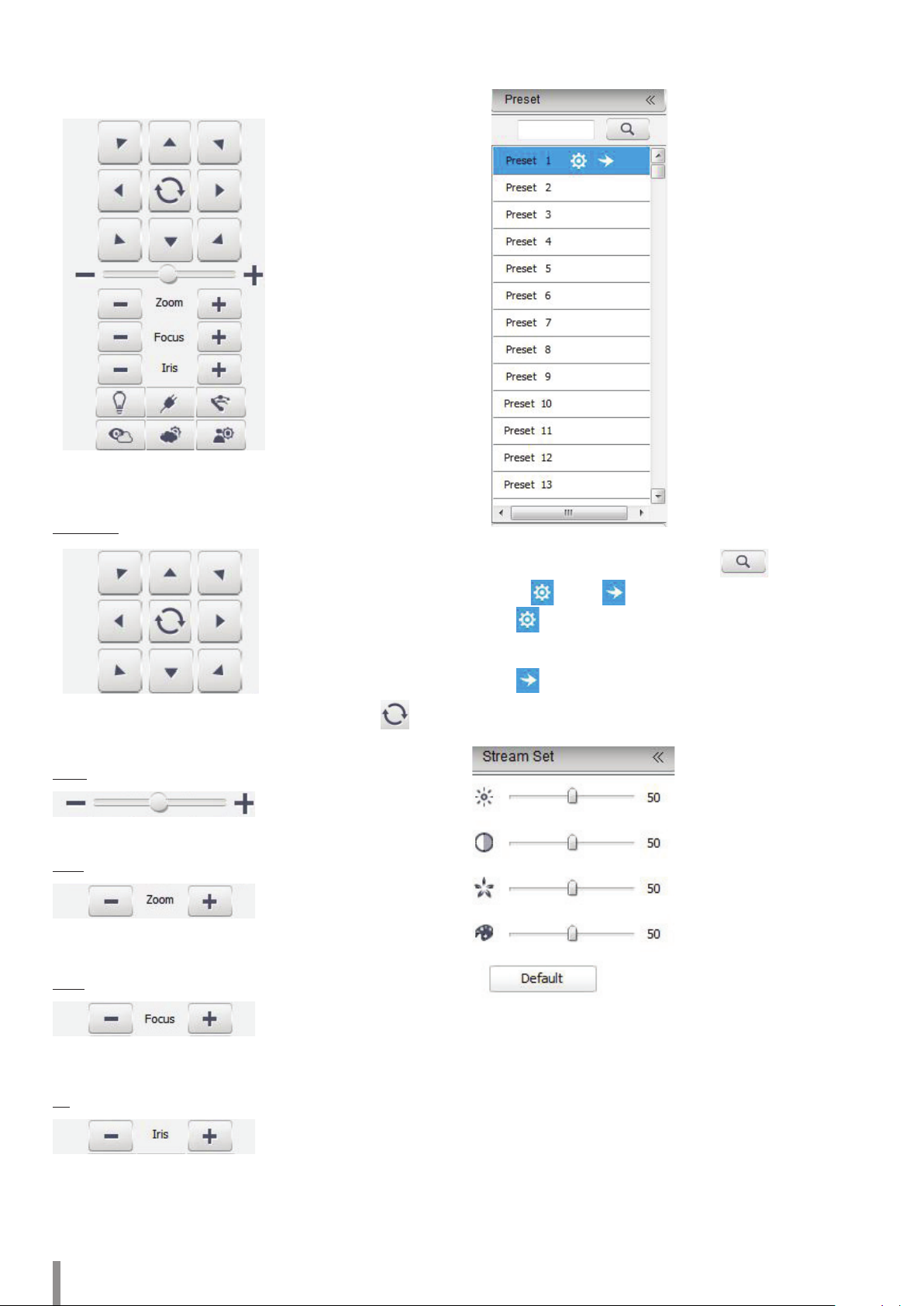
System Settings
PTZ Control
Note:
This function only support camera with RS-485.
PTZ Position
PTZ Control
> It shows eight buttons to control the direction. Click button
to enable auto scan function.
Speed
> Adjust speed by moving adjustment bar. It range from 0 to 100.
Zoom
> Enable to zoom in or zoom out, including optical and digital
zoom.
1. Enter the preset number and click search button.
2. Select
>
>
Stream Set
[Set] or [Call] on the preset position you want.
[Set]
Set the preset and add preset position. It is supported add
multiple presets.
[Call]
Call the preset and make speed dome at preset position.
Focus
1. Click [Stream Set] and open parameter set interface.
> Focus on the object manually according to how far it is when the
auto focus does not work precisely.
Iris
> Manually start or shut down iris.
2. Drag the adjustment bar to set a brightness, contrast, color
saturation.
Note:
• Clik the [Default] button to turn to the default settings.
• It needs restart after revise parameter.
8 Operation and settings
Page 9
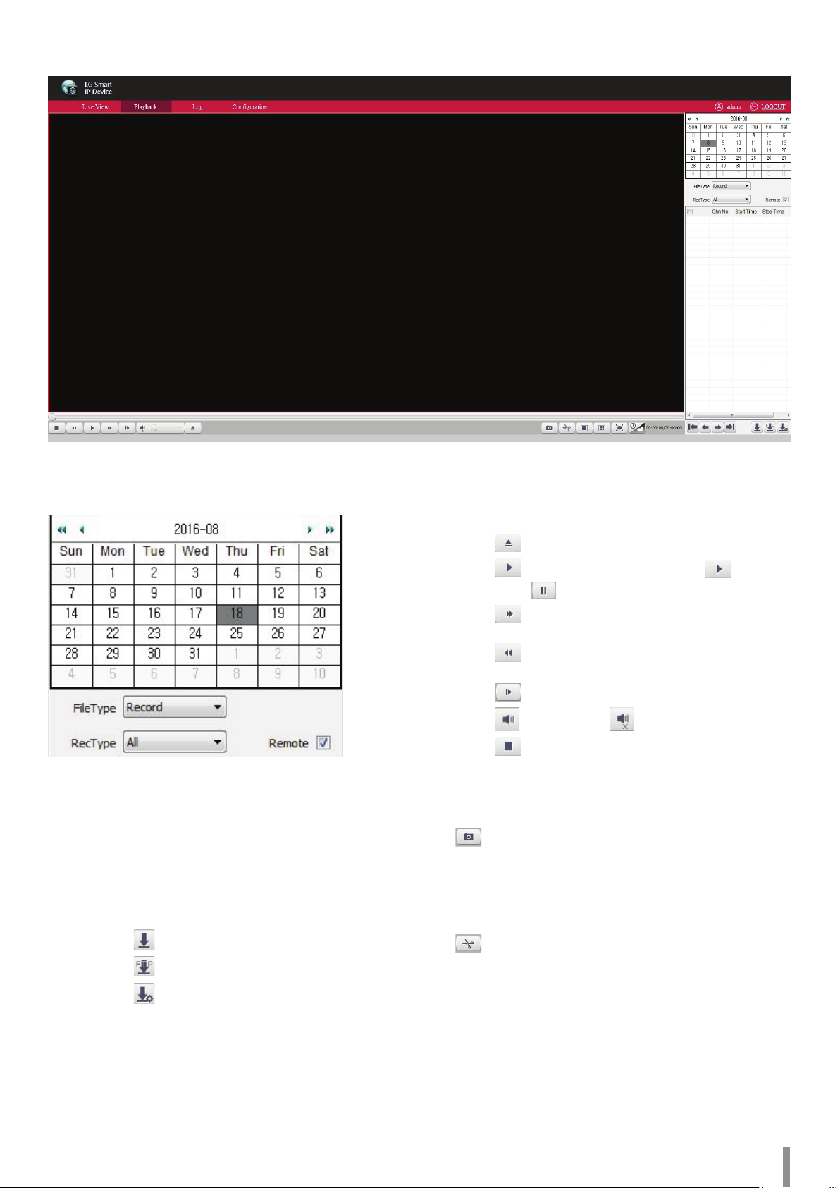
Playback
Search recording les
1. Double click date in the calendar to search files.
2. Select [Record] or [Picture] in [FileType].
3. Check the [Remote] box to select record type.
4. Select targeted file type in [RecType].
Download recording les
Playback
> Double click searched recording files for playback.
> Click
> Click
change into
> Click
2X, 4X, 6X and 8X.
> Click
and 1/8X.
> Click
> Click
> Click
to select local recording files.
to play the playback. When you click , It will
pause icon.
to fast move forwarder in speed of
to move forwarder slowly in speed of 1/2X,1/4X,1/6X
to play frame by frame.
to mute and click once again to cancel mute.
to stop.
Recording snapshot
Click to capture the picture when playback the video.
Default storage path is D:\NetVideoBrowser\ PlaybackPics.
> Check targeted files to download.
- Click
- Click
- Click
delete when you need.
Note:
Download Management only support Local Download.
Operation and settings 9
to download recording files.
to download files into FTP server.
to preview download status, and pause or
Video clip
Click to cut a clip of video when playback the video.
Click once to start and click again to finish.
Default storage path is D:\NetVideoBrowser\ PlaybackFiles.
Page 10

Four screen play
Click to playback in 4 screen at the same time which can play
separately for each screen. Once you select one screen and open the
recording files you want.
Note:
Click
to back to the single screen.
Full screen
Double click the screen or click button to enter full screen status.
To quit full screen mode, double click on screen or enter the [Esc].
Switch mode
Click to playback switch mode.
10 Operation and settings
Page 11
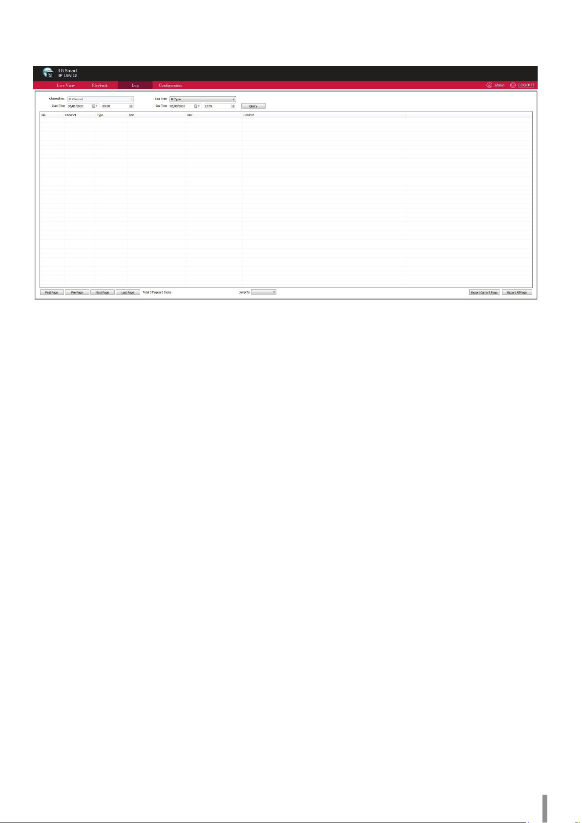
Log searching
Click [Log] to enter the page.
> Channel No. : Select channel which you want to search.
> Log Type : Select log type which of you want to search.
> Start Time : Select start date and time.
> End Time : Select end date and time.
• Query : Make a list of log at the presetting time.
• When there are many pages, you can click [First Page], [Pre Page],
[Next Page], [Last Page] to check the log or [Jump To] the target
page.
• Export Current Page: Click [Export Current Page] to export log of
current page to your computer. It is saved in D:\NetVideoBrowser.
• Export All Page: Click [Export All Page] to export all the pages query
to your computer. It is saved in D:\NetVideoBrowser.
Operation and settings 11
Page 12

Conguring the LG Network Camera Device
The features and options of the LG IP camera are configured through the
[Configuration] menu.
Only administrator-level users have permission to access the
[Configuration] menu.
Accessing the Conguration menu
Click the [Configuration] button to display the LG Smart Web Viewer
configuration window.
Warning:
The [Configuration] setup should be made by qualified service personnel
or system installers.
Conguration
Conguration menu overview
The following table shows the list of menu items.
The configuration images are different from each model.
Main Menu Sub Menu Note
Stream Set
Audio Video Set
Camera Set
VCA
OSD
Storage
Management
Network Management
User Management User Management
Alarm
Management
PTZ Management Serial Port Set RS-485
Advance Set
Audio Set
Key Region
Image Parameter
Image Set
Schedule
D/N Set
Alarm Info
Create Rule
VCA Schedule
Advanced For Technician
OSD
LOGO
Privacy Mask
Record Policy
Pre-Alarm Recording
Storage Set
Snapshot Set
Disk Management
Net Storage
TCP/IP Set
Registration Center
Network Service
IP Filter
Alarm Input
Alarm Output
Motion Alarm
Mask Alarm
Email Alarm
Alarm Server Not support
File Locations
System Set
System Maintenance
Access Platform
12 Operation and settings
Page 13

Audio video set
Advanced Set
Stream Set
Select the stream you want.
General Set
> Stream Type: Select the stream type.
> Resolution: Select the resolution.
Note:
Type of resolution is different according to stream type.
> Bit Rate: Input the bit rate value. It range from 32 to16,384
Kbps.
> Frame Rate: Select the frame rate.
> N/P Mode: Switch the N/P mode to [PAL] or [NTSC].
Note:
This mode is not supported on 3rd stream.
> Priority: Set a priority you want between [Quality] and
[Frame Rate].
Note:
This mode is not supported on 3rd stream.
> Video Quality: Set a video quality you want. The [Better] and
[Best] quality can streaming bandwidth working.
Note:
This mode is not supported on 3rd stream.
> I-Frame Interval: Set the interval time for each two I-frame.
Note:
This mode is not supported on 3rd stream.
> Encoding Mode: You can set a bit rate to constant or variable.
Note:
This mode is not supported on 3rd stream.
> Smooth Video Streaming: Adjust video streaming by moving
adjustment bar from ‘clarity’ to ‘smooth’.
Note:
This mode is not supported on 3rd stream.
• Save: Save all the set up.
• Export: Click [Export] to do backup of the configuration file for all the
parameter. Saves to D:\NetVideoBrowser\VideoParam.dat
• Import: Click [Import] to import the backup file for parameter
configuration. Saves to D:\NetVideoBrowser\VideoParam.dat
Note:
Type of resolution is different according to stream type.
> Corridor Mode: Switch corridor mode to [ON] or [OFF].
Note:
Corridor mode is only supported on more than 720P resolution.
> Video Encoding: Select the video encoding type.
> Extended Code: Select the extended code.
Note:
Extended code can set on [H.264] type only.
> Channel Type: (This mode is not activated.)
> Encrypt Type: Set the encrypt type. It is supported [AES]
encryption and default type is [Not Encrypted].
> Encrypt Password: Enter the password.
> Password Confirm: Enter the password once more.
> Electronic Image Stabilization: Switch the electronic image
stabilization function to [Disable] or [Enable]. Default set is
[Disable].
> SVC: Switch the SVC function to [Disable] or [Enable].
Default set is [Disable].
• Save: Save all the set up.
• Export: Click [Export] to do backup of the configuration file for all the
parameter. Saves to D:\NetVideoBrowser\VideoParam.dat
• Import: Click [Import] to import the backup file for parameter
configuration. Saves to D:\NetVideoBrowser\VideoParam.dat
Operation and settings 13
Page 14

Audio Set
Image Parameter
> Audio Encoding: Select the audio encoding type.
> Audio Sample Rate: Select audio sample rate.
> Audio Control Type: Select audio control type. Active audio input
select [LineIn], passive input select [MicIn].
> Volume Value: Adjust volume value by moving an adjustment bar.
It range from 1 to 100.
> Audio Denoising: To delete the noise from voice, adjust audio
denoising value by moving an adjustment bar.
It range from 1 to 9.
• Save: Save all the set up.
Note:
It needs restart after revise parameter.
Key Region
To have better image quality for some regions on the video, there are 4
regions settable for each video.
> Image Parameter: Select the image parameter to adjust image.
• Save: Save the set up.
> Stream: Select the stream you want.
Note:
This mode is not supported on 3rd stream.
> Upgrade Level: Select upgrade level.
> Start to Draw: Click the [Start to Draw] button to draw the key
region on the video by using a mouse.
> Line Clear: Click the [Line Clear] button to clear the lines.
> Delete Area: Click the [Delete Area] button to delete the drawn
regions.
• Save: Save all the set up.
14 Operation and settings
Page 15

Camera set
Image Set
Set video image parameter in this page.
> Current Template: Choose the template that need to be modified.
The system provides 8 video templates for different application,
all the video parameter can only be revised and saved in the
template.
> Template Name: Input template name.
Image Adjustment
> Adjust the brightness, contrast, saturation, hue and sharpness of
image by moving a adjustment bar.
Exposure Set
Back Light set
> Smart IR: Switch the [Smart IR] function. This function is in IR
camera, when image has over exposured, camera will turn down
the brightness to avoid invisible object phenomenon according to
over exposure.
> HLC: Set the HLC (High Light Control) function to enable or
disable. It mainly used in transportation. When turn on the [HLC],
highlight of car’s headlight will be suppressed.
> WDR: Select WDR mode.
- Close: Disable WDR mode.
- BackLight compensation: Set the apheliotropic area by
clicking the checkbox.
- WDR Auto: Setup the WDR function to automatically. Drag
the slider of [Super-wide dynamic grade] to setup WDR level
fit for environment.
- WDR Manual: Set the WDR function to manually. Drag the
slider of [Super-wide dynamic grade] to setup WDR level fit
for environment.
> Shutter: Setup max exposure time by moving an adjustment bar.
Note:
If exposure time is too long, the image of moving objects will be
slured, and if exposure time too short, the image color will be
more black.
> Gain: Adjust max gain value that affect image brightness.
Note:
When gain value is too high, It will produce much noises.
> Brightness: Adjust the brightness of image by moving an
adjustment bar.
> Auto Aperture: Set the auto aperture function to enable or
disable.
> Auto Exposure Speed: Setup exposure speed by moving an
adjustment bar.
White Balance
> White Balance: Select white balance mode according to the
actual scene. If you select [Semi-auto] or [Handle], you can
adjust red and blue balance to meet demand.
(R is red gain, B is blue gain.)
Operation and settings 15
Page 16

Image Enhancement
D/N Set (Day and Night Setting)
Setup IP camera to switch in day and night with different rules.
> Image Style: Select image style.
> Indoor / Outdoor: Select indoor or outdoor mode.
> Defog: Set the defog function to enable or disable. If you select
the [Enable], you can adjust [Defog] strength value by dragging
slider.
> Digital Noise Reduction (DNR): Digital noise reduction
- Close: Disable DNR mode.
- Ordinary Mode: You can adjust [Denoise Level] by dragging
slider.
- Expert Mode: You can adjust [Space-Domain Denoise] and
[Time-Domain Denoise] by dragging slider.
Note:
Please click [Save] after settings.
• Export: Click [Export] to export current HD parameter template to
certain place (Default address is D:\NetVideoBrowser\HDPara.dat).
This template can be used for other same model cameras.
• Import: Click [Import] to import HD parameter setting file from
default address (Default address is D:\NetVideoBrowser\ HDPara.
dat), to achieve quick configuration.
• Default: When you click the [Default], each template parameters will
restored to factory default settings.
Schedule
User can setup the device to get best images in different time period. It
provides maximum 8 time periods.
To setup schedule for each time periods, check the time line and select
the image mode. To adjust templite time, drag the dividing line. Different
color means different schedule.
> Realtime Brightness: Shows realtime brightness value of video.
> Color to B/W Type:
- Auto(inside): Camera detects the video image automatically.
Video will become color when brightness value higher than
day value; Video will become gray when brightness value
lower than night value.
- B/W: Video is always in gray mode.
- Color: Video is always in color mode.
- Auto(outside): Device detects outside environment
brightness with photoreceptor. Video will become color when
outside brightness value higher day value; Video will become
gray when outside brightness value lower than night value.
(Only for IR camera)
- Schedule: User can adjust the time of day and night.
- Self-adaptive: In color mode, IPC will detect and analysis the
brightnesss by internal synchronization sensor.
When the brightness is lower than the setted night
brightness ,the image will change into B/W in [B/W] mode.
In color mode, IPC will detect and analysis the brightnesss by
external synchronization Photoresistor. When the brightness
is higher than the setted daylight brightness, the image will
change into color.
• Export: Click [Export] export current image schedule to certain place
(default address D:\NetVideoBrowser\ HDSchedulePara.dat ), this
template can be used for other same model cameras.
• Import: Click [Import] import image schedule file from default
address(default address D:\NetVideoBrowser\ HDSchedulePara.dat),
to achieve quick configuration.
16 Operation and settings
Page 17

VCA
Alarm Info
> Event: Select ‘All’ VCA events or other certain event.
> Rule ID: Select ‘All’ rule’s alarm information or other certain alarm
information.
• Clear: Clear all alarm information from current list.
• Reset: Clear current alarm information and begin from one in next
event.
Create Rule
When select [Create Rule] menu, prompt message will displayed
(Tip: During the configuration, the VCA will be suspended!).
Confirm or cancel this message.
[Behavior Analysis]-Event Set: [Tripwire]
> Enable Arithmetic: Behavior Analysis
> Rule ID: Select rule number.
Note:
Check the [Valid]. It draws one rule lines, the arrow of line means
direction of prohibit crossing.
> Rule Name: Insert rule name.
> Event Set: Select [Tripwire].
> Percentage: Setup target size in the total screen (Area percent).
• Save: Save all the settings.
• Next: Go into [Alarm Setup] menu.
[Behavior Analysis]-Event Set: [Double Tripwire]
> Enable Arithmetic: Behavior Analysis
> Rule ID: Select rule number.
Note:
Check the [Valid]. It draws two rule lines. The arrow of line means
direction of prohibit crossing, 2 lines direction should be the
> Enable/Disable: Turn on or off current channel’s VCA function.
> Enable Arithmetic: ‘Behavior analysis’ and ‘Crowd Detection’
functions only can enable one in one time. Video and audio
abnormal detection can work with upon analysis functions at
same time.
Note:
‘Behavior analysis’, ‘Video Detection’ and ‘audio abnormal
detection’ need go into [Alarm Setup] to setup “enable time”
and ”alarm trigger template” after [Save].
• Save: Save VCA settings.
Operation and settings 17
same, it will alarm when target object cross 2 lines continuously
within the specified time.
> Rule Name: Insert rule name.
> Event Set: Select [Double Tripwire].
> Max time interval: Setup maximum time range of cross 2 lines
continuously.
> Min time interval: Setup minimum time range of cross 2 lines
continuously.
> Percentage: Setup target size in the total screen (Area percent).
• Save: Save all the settings.
• Next: Go into [Alarm Setup] menu.
Page 18

[Behavior Analysis]-Event Set: [Perimeter]
> Enable Arithmetic: Behavior Analysis
> Rule ID: Select rule number.
Note:
Check the [Valid]. It draws one rule lines, the arrow of line means
direction of prohibit crossing.
> Event Set: Select [Perimeter].
> Detect mode:
- [Intrusion] mode: It will trigger alarm when object stay in
detection area until reach [Invasion Time(s)].
- [Enter] mode: It will trigger alarm when object go to
detection area.
- [Leave] mode: It will trigger alarm when object go out
detection area.
> Invasion Time(s): Setup invasion time of object stay in detection
area, it will trigger alarm when over the time.
> Percentage: Setup target size in the total screen (Area percent).
• Save: Save all the settings.
• Next: Go into [Alarm Setup] menu.
[Behavior Analysis]-Event Set: [Missing Object Detection]
> Enable Arithmetic: Behavior Analysis
> Rule ID: Select rule number.
Note:
Check the [Valid]. It draws two rule lines. The arrow of line means
direction of prohibit crossing, 2 lines direction should be the
same, it will alarm when target object cross 2 lines continuously
within the specified time.
> Rule Name: Input a rule name.
> Event Set: Select [Missing Object Detection].
Note:
Please notice the detection area shouldn’t overlap when
[Object Abandone] and [Missing Object Detection] are enable at
same time.
> Alarm Time: Setup alarm time of object lost in detection area, it
will trigger alarm when over the time.
> Percentage: Setup target size in the total screen (Area percent).
• Save: Save all the settings.
• Next: Go into [Alarm Setup] menu.
[Behavior Analysis]-Event Set: [Object Abandone]
> Enable Arithmetic: Behavior Analysis
> Rule ID: Select rule number.
Note:
Check the [Valid]. It draws two rule lines. The arrow of line means
direction of prohibit crossing, 2 lines direction should be the
same, it will alarm when target object cross 2 lines continuously
within the specified time.
> Rule Name: Input a rule name.
> Event Set: Select [Object Abandone].
> Alarm Time: Setup alarm time of object stay in detection area,
it will trigger alarm when over the time.
> Percentage: Setup target size in the total screen (Area percent).
• Save: Save all the settings.
• Next: Go into [Alarm Setup] menu.
18 Operation and settings
Page 19

[Behavior Analysis]-Event Set: [Loiter]
[Behavior Analysis]-Event Set: [Parking]
> Enable Arithmetic: Behavior Analysis
> Rule ID: Select rule number.
Note:
Check the [Valid]. It draws one rule lines, the arrow of line means
direction of prohibit crossing.
> Rule Name: Input a rule name.
> Event Set: Select [Loiter].
> Alarm Time: Setup alarm time of object stay in detection area, it
will trigger alarm when over the time.
> Sensitivity: Adjust sensitivity value. As value increases, more
sensitive.
> Min Area: Adjust minimum area percentages. When the object’s
motion area is equal or greater than this [Min Area], alarm
function will activated.
• Save: Save all the settings.
• Next: Go into [Alarm Setup] menu.
[Behavior Analysis]-Event Set: [Running]
> Enable Arithmetic: Behavior Analysis
> Rule ID: Select rule number.
Note:
Check the [Valid]. It draws one rule lines, the arrow of line means
direction of prohibit crossing.
> Rule Name: Input a rule name.
> Event Set: Select [Parking].
> Alarm Time: Setup alarm time, alarm when the object keep
parking to this alarm time.
> Percentage: Setup target size in the total screen (Area percent).
> Speed Threshold: Setup speed threshold value. When moving
speed (percent / second) is slower than this [Speed Threshold],
alarm function will activated.
• Save: Save all the settings.
• Next: Go into [Alarm Setup] menu.
[Crowd Detection]-Arithmetic: [Crowd Detection]
> Enable Arithmetic: Select the [Crowd Detection].
> Save: Save the [Crowd Detection] setting.
> Arithmetic: Set the [Crowd Detection].
> Alarm Time(s): Set the time of linking to alarm.
> Enable Arithmetic: Behavior Analysis
> Rule ID: Select rule number.
Note:
> Percentage: Set the crowd percentage.
• Save: Save all the settings.
• Next: Go into [Alarm Setup] menu.
Check the [Valid]. It draws one rule lines, the arrow of line means
direction of prohibit crossing.
> Rule Name: Input a rule name.
> Event Set: Select [Running].
> Minimum Area: Adjust minimum area percentages. When the
object’s motion area is equal or greater than this [Minimum
Area], alarm function will activated.
> Percentage: Setup target size in the total screen (Area percent).
• Save: Save all the settings.
• Next: Go into [Alarm Setup] menu.
Operation and settings 19
Page 20

[Video Detection]-Arithmetic: [Video Detection]
> Enable Arithmetic: Select the [Video Detection].
> Save: Save the [Video Detection] setting.
> Arithmetic: Set the [Video Detection].
> Lens Diagnose: Check the [Lens Diagnose] to enable lens.
> Sceen Switch Diagnose: Check the [Sceen Switch Diagnose] to
enable screen switch.
> Sensitivity: You can set the sensitivity value. Higher value means
more sensitive.
• Save: Save all the settings.
• Next: Go into [Alarm Setup] menu.
[Audio Detection]-Arithmetic: [Audio Detection]
VCA Schedule
Alarm Set
> Rule ID: Select the [Rule ID] to active the rule.
> Rule Name: Enter the rule name to active the rule.
> Event: Displays Rule ID information.
> Schedule: Set schedule date and time.
> Link Type: Select the link type.
- Alarm Output
- Link Rec
- Link PTZ
- Link Snap
> Output Port: Check the output port [All] or specific port number.
• Save: Save all the settings.
> Enable Arithmetic: Select the [Audio Detection].
> Save: Save the [Audio Detection] setting.
> Arithmetic: Set the [Audio Detection].
> Signal Loss Detection: Enable signal loss.
> Signal Abnormal Detection: Enable abnormal detection.
> Sensitivity: You can set the sensitivity value. Higher value means
more sensitive.
• Save: Save all the settings.
• Next: Go into [Alarm Setup] menu.
Advanced
Note:
[Advanced] is only available for company engineer to setup.
20 Operation and settings
Page 21

OSD
OSD
This function is used to add more information on the preview screen.
Privacy Mask
This function is used for setting hidden region on the preview screen to
protect important information. It supports up to 4 regions.
> Camera Title: Check the [Camera Title] and input a channel name.
- Customized Location: Select position of channel name on
video image by mouse.
- Color: Select OSD color.
> Date: Check the [Date] and select the date you want. There are
11 formats for option.
- Customized Location: Select position of date which you
selected on video image by mouse.
- Color: Select OSD color.
- Show Week: Check the [Show Week] to overlay week
information on image.
- 24 hours / 12 hours: Select time you want.
> Additional Text: Select additional text area number (max 5).
Then input overlay contents. It supports English and common
punctuation marks.
- Customized Location: Select position on video image by
mouse.
- Color: Select OSD color.
Note:
You can not use special character in additional information
(such as # % * \ ; ‘ “).
> OSD Size: Select suitable pixel size. Default size is [Self-adaptive].
> Fonts Type:
- Vector / Lattice: Optional
> Save: Save all the settings.
LOGO
This function is used to overlay Logo picture on the preview screen.
> Draw the region on the screen by mouse. It supports up to
4 regions.
> Delete Region: Delete the drawn region.
Storage Management
Record Policy
> Record Status: Shows the device recording status.
- Manual Rec: Enable to start recording and cancel to stop.
- Alarm Rec: Enable to start recording when alarm is triggered.
- Continuous: Enable to start timing recording.
> Schedule: Setup time period in [Continuous] mode.
> Offline Video Recording: On or off of the offline video recording
function. When the internet is disconnected, it will start timing
recording into camera SD card.
• Save: Save all the setup.
> LOGO File
- Browse: Browse files to find the logo.
- Upload: Upload the logo file, IP camera will restart. After
restart, please check [Enable] to display the logo.
> Customized Location: Select logo position on video image.
Note:
Logo format should be 24bit bmp and size should be less than
200*200. Height and width are divisible by 4 System. It will
remove black and white picture of background automatically.
Operation and settings 21
Page 22

Pre-Alarm Recording
This function is used for pre-recording before alarm is triggered and
extending recording time after alarm disappeared.
> Pre-Alarm Recording: Check [Pre-Alarm Recording] to enable to
start.
> Pre-alarm time (5-15)s: It is supported Support5s, 10s and 15s.
> Post-alarm time (10-60)s: It is supported 10s, 15, 30s and 60s.
• Save: Save all the setup.
Snapshot Set
> Timing Capture: Enable to start timing capture.
> Interval: Set timing capture interval time.
> Capture Link
- Link FTP: Captured pictures will be uploaded to FTP server.
- Link Email: Capture picture will be sent by email.
• Save: Save all the setup.
Storage Set
> Free Disk Space(MB): Set the free disk space that custom you
want to keep. It should be larger than 512MB.
> When HDD is full: When the free disk space reached the target
size, system will run the following operation.
- Stop Rec: It will stop recording.
- Overwrite: It will delete the earliest record file.
- Overwrite (Exclude Alarm Record Videos): It will delete the
earliest record file except alarm.
• Save: Save all the setup.
Disk Management
> Disk Information: Display the disk status.
> Initialize Disk: The new hard disk must be initialized first.
Net Storage
> Disk No.: Select one disk to setup.
> Status: Show the disk installation status. [UnMounted],
[Unformatted], [Formated], [Mounted] and [Using] are optional.
> Usage: Show the disk usage status. [Record], [Backup],
[Redundant] and [Read Only] are optional.
> IP Address: Set NFS server IP address.
> Mapping Path: Set the disk mapping path.
> Total Size: Display the free space and total size.
• Save: Save all the setup.
22 Operation and settings
Page 23

Network Management
Network Service
TCP/IP Set
> DHCP: Check the [DHCP] to enable DHCP server. It will
automatically allocate IP address for devices.
> IPv4 Address / IPv6 Address: Displays IPV4, IPV6 address.
> IPv4 Subnet Mask / IPv6 Subnet Mask: Displays IPV4, IPv6
subnet mask.
> MAC: Displays Multi Access Computer.
> MTU: Maximum Transmission Unit. It range from 500 to 1500.
Default value is 1500.
> Ethernet Rate(M): Select mode and rate of Ethernet card, speed
unit is MB. Default mode is [Automatic Detection], modify not
recommended.
Note:
Devices will restart after change [Ethernet Rate(M)] setting.
• Save: Save all the setup.
DDNS
> Enable: Check the [Enable] to enable DDNS.
> Server Domain: Modify sever domain.
> DDNS Domain: Modify DDNS domain.
> User Name: Enter the user name.
> Password: Enter the password.
> Password Confirm: Enter the password once more.
• Save: Save all the setup.
Note:
For using DDNS, user must register the domain to the DDNS server.
Registration process and instructions has guided in related site.
FTP
Registration Center
> Server Name: Set the server name.
> IP adress1 / IP adress2: Set the IP addresses.
> Port1 / Port2: Set the ports.
> User Name: Enter the user name.
> Password: Enter the password.
• Save: Save all the setup.
> Server URL: Enter the server URL.
> Port: Set the port.
> Path: Enter the path to download.
> User Name: Enter the user name.
> Password: Enter the password.
• Save: Save all the setup.
Operation and settings 23
Page 24

PPPoE
> Enable: Check the [Enable] to enable PPPoE function.
> User Name: Enter the user name.
> Password: Enter the password.
> Password Confirm: Enter the password once more.
• Save: Save all the setup.
MUC (Multicast)
> IP Address: Enter the IP address.
> Port: Set the port.
• Save: Save all the setup.
Other
NTP
> NTP Server: Enter the NTP server.
> Port: Set the port.
> Time Interval(minute): Set the interval.
• Save: Save all the setup.
> UPnP Enable: Check the [UPnP Enable] box and restart the
device to enable the UPnP function.
> SNMP Enable: Check the [SNMP Enable] box and restart the
device to enable the SNMP function.
> HTTP Port: Enter the HTTP port, then restart device.
> HTTPS Port: Enter the HTTPS port, then restart device.
> RTSP Port: Enter the RTSP port, then restart device.
• Save: Save all the setup.
24 Operation and settings
Page 25

IP Filter
Blacklist and whitelist also named [IP filter], used to manage the access
right of users.
> Setup IP filter.
- Forbidden: Cancel all the blacklist and whitelist.
- Blacklist: It used to block some IP address. Input the block IP
address and click [Add], [Save]. Max to add 16 blacklist IP
address.
Note:
Please don’t add your own IP address in blacklist, otherwise
you will not be able to login.
- Whitelist: Selects only some IP address allowed. Input trusted
IP address and click [Add], [Save]. Max to add 16 whitelist
IP address.
Note:
Once enable the whitelist function, please make sure to add
your own IP address in whitelist, otherwise you will not be
able to login the device.
> Add: Add block IP address or trusted IP address according to
IP filter setting.
> Delete: Delete certain IP address. Select the left check box and
click [Delete].
• Save: Save all the set up.
Note:
The IP filtering can only recognize when the new user login, but
not work for ready IP. It is strongly recommended that restart the
equipment each time after configuring blacklist and whitelist.
User management
User management
Add user
Click [Add] button on [User Management] to add user.
Note:
Only the administrator can add and modify users.
> User Name: Input user name.
> Password: Input password.
> Password Confirm: Input password once more.
Note:
The user name and password can only input English letters and
Numbers.
> Authority
- Browse: Preview and Playback.
- Browse + Control: Preview, Playback, Control PTZ and Log.
- Browse + Control + set: Allow all operation except user
authority.
- Admin: All operations available.
• Add: Click [Add] to add user.
Modify password
Select a user you want to modify password in user list.
> Modify Pwd: Click [Modify Pwd] button on [User Management]
to modify password.
> Old Pwd: Input the existing password.
> New pwd: Input the password to modify.
> Password Confirm: Input the modified password once more.
• Modify: Click this button to save settings.
Operation and settings 25
Page 26

Delete User
Select the user you want to delete in the user list.
> Delete: Click [Delete] button on [User Management] menu to
delete user.
Alarm Management
Alarm Input
Alarm Output
> Output Port: Select the output port.
> Mode Set: Select the mode set ON or OFF.
> Delay Time(s): Select the delay time.
• Save: Save all the set up.
Motion Alarm
> Input port: Select [Input port] and check [Enable] box to valid the
port alarm function. To close the alarm detection function,
cancel it.
> Mode set: Switch the mode of function ON or OFF. It Included
closed circuit alarm and open circuit alarm functions.
- ON: Closes circuit alarm. It will alarm when disconnected
circuit occurs short-circuit.
- OFF: Opens circuit alarm. There was an alarm when the
connected circuit disconnect.
> Schedule: Set the date and time. It only alarms during the
schedule.
> Link Type: Set an alarm activation.
- Alarm Output
- Link PTZ
- Link Snap
• Save: Save all the set up.
• Copy to...: Copy to another output port.
Note:
The Alarm function only available for products which support
Alarm In / Out.
> Check the [Enable] box to enable [Motion Alarm]. Then draw
the area by dragging mouse left button. Click [Delete Region] to
clean the draw area.
> Sensitivity: It range from 0 to 100. Small value means the higher
sensitivity.
> Schedule: Set the date and time. It only alarm during the
schedule.
> Link Type
- Alarm Output
- Activate Dual Light: It only used for the model which have
double light. At night, motion detection link white light on.
Under “Night Mode” (“White & Black” mode), IR LED on.
Under “Day mode”(“Color” mode), IR LED off. Motion alarm
disappear, double light off.
Note:
When white LED lights on by detecting motion, under the
conditions of the camera videos are converted into black and
white, determine night and day mode of video.
Night mode: Maintains the B/W.
Day mode: Maintains the Color.
- Link Snap
• Save: Save all the set up.
26 Operation and settings
Page 27

Mask Alarm
When the video is covered, system will alarm according to the sensitivity
setting.
> Check the “Enable” box to enable Video Occlusion Detection
function.
> Sensitivity: Smaller number means more sensitive.
> Schedule: Video Occlusion Detection works only during this
schedule time.
> Link Type: Set to achieve linking (such as link PTZ) after alarm is
triggered.
• Save: Save all the set up.
Email Alarm
After this function is enabled, the alarm server will automatically send
email to the setting email address when alarm is triggered.
Alarm Server
> Alarm Server: Alarm server information can be customized.
Input address.
> Port: Input port number.
• Save: Save all the set up.
PTZ Management
Serial Port Set
PTZ management includes [Serial Port Set] and [Protocol Set].
Note:
After connecting the device that supported RS-485 communications to
an IP camera, set the serial port to use the device.
> Check the ‘Email Alarm Enable’ box to enable this function.
> Email Server: Address format should be “smtp.xx.com”. XX Stand
for email server such as “smtp.gmail.com”.
> Email Port: Default number is 25.
> Email Account: Enter the email account for sending email.
> Email Password: Enter the email password for the sending email.
> Email Mode: Select email mode. [login] is suggested.
> Encryption: Select encryption mode.
> Email Subject: Input the email subject.
> Email Address: Set the email address. It is for the receiving email.
• Save: Save all the set up.
• Test: Test email alarm function.
Operation and settings 27
Page 28

Advance Set
File Locations
> Stream: Select the stream for a certain channel.
> Display frame and bit rate information: Check to display frame
rate and bit stream on video.
• Browse: Click to choose save path of files.
> Play Performance: Set to achieve the balance between ‘fluency’
and ‘delay’.
> Protocol Type: Select the protocol type.
> Local Capture Format: Select the capture saving format.
System set
System Maintenance
> Device Control
- Factory Default
- Reboot
- Iris Correction
- Lens Reset
- Open remote service
> Firmware Upgrade: Upgrades new firmware (firmware format:
.box/.bin). Upgrade process normally needs a few minutes until
indication for completion. Please strictly follow the instruction by
technical specialist for firmware upgrade.
> Configuration In/Out: Includes three types of specification:
- Alarm: This specification includes alarm schedule and linkage
info. VCA info is not included.
- VCA: This specification includes schedule, rule and related
setting.
- System Set: This specification includes the other information
except ‘Alarm’ and ‘VCA’ specification such as OSD, Recording
strategy, Internet set and some other setting.
> System Information: Displays information of [CPU], [Memory]
and [FLASH].
Note:
When you click the [Refresh] button, a display information value
can be changed according to current conditions.
> Version Information: Displays version informations of the device.
> Language and Timezone: Set the time zone and time
synchronous.
- Daylight-Saving Time: Check to enable daylight saving time
function.
• Save: Save all the set up.
Access Platform
PU set
> User can set the IP address and port number of [Register Server],
[Heartbeat Server], [Alarm Server] and VSP’s port number and
VAP’s port number.
> [Channel No.] support [Auto Filling Set] function.
28 Operation and settings
Page 29

• Save: Save all the set up.
SIP Set
> User can set the [SIP set]
> [Channel No.] support [Auto Filling Set] function.
• Save: Save all the set up.
Platform Enabled
> Platform List: Enable or disable [onvif]. System will reboot
automatically after setting.
Note:
Current platform must be disabled before changing into a new
platform.
Operation and settings 29
Page 30

Reference
Troubleshooting
This section provides useful information to help you to resolve any difficulty you might have with your LG IP device.
Symptoms Solution
Disk partition information has problem, which cause no recognition, need formatting for the disk.
Not able to recognize USB or
SD card
No recognition on
Wireless Network Card
Camera was power on but
cannot be found on IP searcher.
No image on IE
Displayed incorrect image after
login
Loose connection, re-plug USB / SD card and reboot the camera.
For portable disk, it may fail when there is not enough power, need to check the power supply method to make
sure enough power supply or change to use independent power supply disk.
Static turn the network card into protection state, need to reboot the camera.
Unstable condition on the network card, need to replace for new network card.
Check status of computer / host NIC, NIC driver, network wire, and network connection, make sure all are correct.
Directly connect the camera to computer / host server to check it works or not, reset the computer / host server
and try again.
Try another camera or another computer / host server
It needs to download and install the ActiveX plug-in for IE browsing at first connection.
There is other device in the some network with same IP and Mac address.
Disconnect the camera, try to ping the network to check whether there is return package.
Use the IP searcher to check whether there are devices with same IP address, then disconnect the other devices
to make sure the IP address of the camera is unique.
It is ok to ping the server, but
cannot properly login
UDP unable to connect video
Video of two camera appear
alternately, or connect and
disconnect in sometime
Public network connection, login and select the port that is mapping to other equipment’s port.
Port 3001 is banned by the firewall.
Wrong port number or user ID or password is incorrect when logging in.
Too many access to the camera. Be set in prohibit list.
Use IP searcher to check the listen port of the camera, make sure it is the same as the software.
Other client already connect to the camera on the same computer.
UDP port conflict with other application program on the same computer, revise camera IP address and test again.
Camera IP address conflict with other computer IP address
If conflict on MAC address, check on IP searcher.
If conflict on IP address, check on the IP searcher
30 Reference
Page 31

Incorrect connection of video on
IE
Make sure host IP address is in the same network segment with the camera.
Make routing if in different network segment.
Make sure to use IE at version 9.0 or higher.
Make sure driver for graphic card and DirectX are installed properly, it is recommended to install the latest version
driver.
Make to enable ActiveX plug-in.
Turn off Anti-virus software and firewall to test.
Delete the installed plug-in, download again and re-install to test.
Use another computer / host server to test.
Contact service center if still had problem.
Cannot connect sub-stream
Control Failure
Video display properly in the
software, but it is unstable or
intermittent or lose frame
Connection is correct but
screen is black or video image is
anamorphic
Access to camera are full.
It is able to control Pan / Tilt / Zoom in IE, but cannot control in the software.
Make sure the control protocol is correct.
Make sure address for PTZ camera is correct set in software.
Exit the software, check the CPU utilization of the computer, make sure the computer configuration is capable to
run the software and there is no virus.
Ping the camera from the computer to check whether there is dropout.
Test network bandwidth, if it is not enough or unstable, please contact the Internet Service Provider.
Please lower down the resolution or image quality when need fluent video in narrow network bandwidth.
Please check if it open VCA functions, please close VCA function, then try again.
DirectX version lower than 9.0. Check the DirectX version.
Graphic card driver incorrect, which disable the accessory function of DirectX; set full screen privacy mask.
Please make sure software version is correct.
Make sure IP address and server type is correct in software. It is suggested to use “Main stream + TCP” type in
Video display properly in IE but
LAN, and “Sub-stream +TCP” in WLAN.
abnormal in software
Make sure video are all connected in the software main interface.
Reboot the software to connect again.
Make sure the computer audio card driver connection is correct, please try to play some music to test.
Make sure to selected Video / Audio not only Video in camera setting.
Video display and control
properly but no audio
Make sure the audio channel is correct.
Make sure the microphone is connected properly.
Reference 31
Page 32

Make sure using active microphone.
Weak Audio Signal
No Alarm Output
Suddenly loses power after
setup the parameter
USB become smaller after used
in camera
Increase the sensitivity of the microphone.
Use active loudspeaker for audio playing.
Make sure output wiring is correct.
Make sure power input voltage; AC 24 V / DC 12 V, electricity; 2A
Check the setting for input / output port in IE.
Make sure the alarm device is working properly.
Parameter is set to save properly after 1 minute, unless reset the camera automatically.
USB and the SD card were formatted by the special division operation on the camera, the result in part of
capacity on the computer can not be identified.
Reformat USB or SD card by BOOTICE.EXE software on the PC.
Open Source Software Notice Information
To obtain the source code under GPL, LGPL, MPL, and other open source licenses, that is contained in this product, please visit
http:// opensource.lge.com.
In addition to the source code, all referred license terms, warranty disclaimers and copyright notices are available for download.
LG Electronics will also provide open source code to you on CD-ROM for a charge covering the cost of performing such distribution (such as the cost of
media, shipping, and handling) upon email request to opensource@lge.com. This offer is valid for three (3) years from the date on which you purchased
the product.
32 Reference
Page 33

Specications
Item LNU7260R
Image Device 1 / 2.8” Exmor CMOS
Lens Type 3.3 - 10 mm, Motorized Lens
Day / Night Dual ICR
Camera
Video / Audio
Event
Minimum Illumination
IR Distance 30 m
Image Enhancement Configurable Brightness, Saturation, Contrast, Flip Mode, HLC, Smart Defog, Corridor, EIS
Compression H.265, H.264 HP / MP / BP, M-JPEG
Resolution
Maximum Frame Rate 60 fps @1280 × 720
Multi-Streaming Up to 3
ROI (Smart-Codec) Support (Up to 4 zones)
Video Analytics
Text Overlay Support
Audio Compression G.711, G.726, ADPCM, AAC
2-way Audio Support
Audio Detection Support
Event Trigger Motion Detection, IP Conflict, Port Alarm
Event Notification Relay Out, Email, FTP
Color: 0.03 lux @ F1.4 (AGC ON)
B/W: 0 lux @ IR LED on
60 Hz: 1080p @ 30 fps, 960p @ 30 fps, 720p @ 60 fps
50 Hz: 1080p @ 25 fps, 960p @ 25 fps, 720p @ 50 fps
Tripwire, Perimeter, Missing&Foreign object, Crowd, Loitering, Fast Moving, Parking,
Audio Offline
Interface
Network
General
Pre-Alarm Recoding Support
Analog Out 1 BNC Out
Audio In / Out 1 In / 1 Out
Alarm In / Out 2 In / 1 Out
SD Slot Micro SD (Up to 128 GB)
RS-485 Support
Ethernet RJ-45 10, 100 BASE-T
Security Password protection, IP filter
Open Protocol ONVIF (Profile S)
Protocol
Integrated Software Mobile application (iPhone, iPad, Android)
Connections Up to 4 Level, 8 Users
Power Source DC 12 V, AC 24 V, PoE
Maximum Power Consumption 12.5 W
Maximum Input Current 890 mA (AC 24 V), 980 mA (DC 12 V), 260 mA (PoE)
Operation Temperature / Humidity -30 ˚C to 60 ˚C / 0 % RH to 95 % RH
Protection IK10, IP66
IPv4/IPv6, HTTP, 802.1x, FTP, SMTP, UPnP, SNMP, DNS, DDNS, NTP, RTSP, TCP, UDP, DHCP,
PPPoE
Dimension (W x H x D) 97.1 mm × 89.4 mm × 311.8 mm
Weight 1.3 kg
Reference 33
Page 34

Item LNU5460R
Image Device 1 / 3” CMOS
Lens Type 3.3 - 10 mm, Motorized Lens
Day / Night Dual ICR
Camera
Video / Audio
Minimum Illumination
IR Distance 30 m
Image Enhancement Configurable Brightness, Saturation, Contrast, Flip Mode, HLC, Smart Defog, Corridor, EIS
Compression H.265, H.264 HP / MP / BP, M-JPEG
Resolution
Maximum Frame Rate 30fps @ 1920 × 1080, 60fps @ 1280 × 720
Multi-Streaming Up to 3
ROI (Smart-Codec) Support (Up to 4 zones)
Video Analytics
Text Overlay Support
Audio Compression G.711A, G.711U, ADPCM, AAC
2-way Audio Support
Audio Detection Support
Event Trigger Motion Detection, IP Conflict, Port Alarm
Color: 0.5 lux @ F1.4 (AGC on)
B/W: 0 lux @ IR LED on
60 Hz: 1440p @ 25fps, QXGA @ 25fps, 1080p @ 30fps, 960p @ 30fps,
720p @ 30fps
50 Hz: 1440p @ 25fps, QXGA @ 25fps , 1080p @ 25fps, 960p @ 25fps,
720p @ 25fps
Tripwire, Perimeter, Missing&Foreign object, Crowd, Loitering, Fast Moving, Parking,
Audio Offline
Event
Interface
Network
General
Event Notification Relay Out, Email, FTP
Pre-Alarm Recoding Support
Analog Out 1 BNC Out
Audio In / Out 1 In / 1 Out
Alarm In / Out 2 In / 1 Out
SD Slot Micro SD (Up to 128 GB)
RS-485 Support
Ethernet RJ-45 10, 100 BASE-T
Security Password protection, IP filter
Open Protocol ONVIF (Profile S)
Protocol
Integrated Software Mobile application (iPhone, iPad, Android)
Connections Up to 4 Level, 8 Users
Power Source DC 12 V, AC 24 V, PoE
Maximum Power Consumption 12.5 W
Maximum Input Current 890 mA (AC 24 V), 980 mA (DC 12 V), 260 mA (PoE)
Operation Temperature / Humidity -30 ˚C to 60 ˚C / 0 % RH to 95 % RH
IPv4 / IPv6, HTTP, 802.1x, FTP, SMTP, UPnP, SNMP, DNS, DDNS, NTP, RTSP, TCP, UDP, DHCP,
PPPoE
Protection IK10, IP66
Dimension (W x H x D) 97.1 mm × 89.4 mm × 311.8 mm
Weight 1.3 kg
34 Reference
Page 35

Item LNV7260R
Image Device 1 / 2.8” Exmor CMOS
Lens Type 3.3 - 10mm, Motorized Lens
Day / Night Dual ICR
Camera
Video / Audio
Event
Minimum Illumination
Color: 0.03 lux @ F1.4 (AGC ON)
B/W: 0 lux @ IR LED on
IR Distance 30 m
Image Enhancement Configurable Brightness, Saturation, Contrast, Flip Mode, HLC, Smart Defog, Corridor, EIS
Compression H.265, H.264 HP / MP / BP, M-JPEG
Resolution
60 Hz: 1080p @ 30fps, 960p @ 30fps, 720p @ 60fps
50 Hz: 1080p @ 25fps, 960p @ 25fps, 720p @ 50fps
Maximum Frame Rate 30 fps @ 1920 × 1080, 60 fps @ 1280 × 720
Multi-Streaming Up to 3
ROI (Smart-Codec) Support (Up to 4 zones)
Video Analytics
Tripwire, Perimeter, Missing&Foreign object, Crowd, Loitering, Fast Moving, Parking,
Audio Offline
Text Overlay Support
Audio Compression G.711A, G.711U, ADPCM, AAC
2-way Audio Support
Audio Detection Support
Event Trigger Motion Detection, IP Conflict, Port Alarm
Event Notification Relay Out, Email, FTP
Interface
Network
General
Pre-Alarm Recoding Support
Analog Out 1 BNC Out
Audio In / Out 1 In / 1 Out
Alarm In / Out 2 In / 1 Out
SD Slot Micro SD (Up to 128 GB)
RS-485 Support
Ethernet RJ-45 10, 100 BASE-T
Security Password protection, IP filter
Open Protocol ONVIF (Profile S)
Protocol IPv4 / IPv6, HTTP, FTP, SMTP, UPnP, SNMP, DNS, DDNS, NTP, RTSP, TCP, UDP, DHCP, PPPoE
Integrated Software Mobile application (iPhone, iPad, Android)
Connections 4 Level, 8 Users
Power Source DC 12 V, AC 24 V, PoE
Maximum Power Consumption 11 W
Maximum Input Current 810 mA (AC 24 V), 880 mA (DC 12 V), 230 mA (PoE)
Operation Temperature / Humidity -30 ˚C to 60 ˚C / 0 % RH to 95 % RH
Protection IK10, IP66
Dimension (W x H x D) 150 mm × 122 mm
Weight 0.96 kg
Reference 35
Page 36

Item LNV5460R
Image Device 1 / 3” CMOS
Lens Type 3.3 -10mm, Motorized Lens
Day / Night Dual ICR
Camera
Video / Audio
Minimum Illumination
IR Distance 30 m
Image Enhancement Configurable Brightness, Saturation, Contrast, Flip Mode, HLC, Smart Defog, Corridor, EIS
Compression H.265, H.264 HP / MP / BP, M-JPEG
Resolution
Maximum Frame Rate 30 fps @ 2048 × 1536, 60 fps @ 1280 × 720
Multi-Streaming Up to 3
ROI (Smart-Codec) Support (Up to 4 zones)
Video Analytics
Text Overlay Support
Audio Compression G.711A, G.711U, ADPCM, AAC
2-way Audio Support
Audio Detection Support
Event Trigger Motion Detection, IP Conflict, Port Alarm
Color: 0.5 lux @ F1.4 (AGC on)
B/W: 0 lux @ IR LED on
60 Hz: 1440p @ 25fps, QXGA @ 25fps ,1080p @ 30fps, 960p @ 30fps,
720p @ 30fps
50 Hz: 1440p @ 25fps, QXGA @ 25fps ,1080p @ 25fps, 960p @ 25fps,
720p @ 25fps
Tripwire, Perimeter, Missing&Foreign object, Crowd, Loitering, Fast Moving, Parking,
Audio Offline
Event
Interface
Network
General
Event Notification Relay Out, Email, FTP
Pre-Alarm Recoding Support
Analog Out 1 BNC Out
Audio In / Out 1 In / 1 Out
Alarm In / Out 2 In / 1 Out
SD Slot Micro SD (Up to 128 GB)
RS-485 Support
Ethernet RJ-45 10, 100 BASE-T
Security Password protection, IP filter
Open Protocol ONVIF (Profile S)
Protocol IPv4 / IPv6, HTTP, FTP, SMTP, UPnP, SNMP, DNS, DDNS, NTP, RTSP, TCP, UDP, DHCP, PPPoE
Integrated Software Mobile application (iPhone, iPad, Android)
Connections 4 Level, 8 Users
Power Source DC 12 V, AC 24 V, PoE
Maximum Power Consumption 11 W
Maximum Input Current 810 mA (AC 24 V), 880 mA (DC 12 V), 230 mA (PoE)
Operation Temperature / Humidity -30 ˚C to 60 ˚C / 0 % RH to 95 % RH
Protection IK10, IP66
Dimension (W x H x D) 150 mm × 122 mm
Weight 0.96 kg
36 Reference
Page 37

 Loading...