

LG LNU5100R series Owner's Manual
Warning: Do not install this equipment in a
confined space such as a bookcase or similar
unit.
Warning: Wiring methods shall be in
accordance with the National Electric Code,
ANSI/NFPA 70.
Warning: This is a class A product. In a
domestic environment this product may cause
radio interference in which case the user may
be required to take adequate measures.
Warning: To reduce a risk of fire or electric
shock, do not expose this product to rain or
moisture.
Caution: This installation shall be made by a
qualified service person and shall conform to
all local codes.
Caution: To avoid electrical shock, do not
open the cabinet. Refer servicing to qualified
personnel only.
Caution: The apparatus shall not be exposed
to water (dripping or splashing) and no objects
filled with liquids, such as vases, shall be
placed on the apparatus.
Note:
Please make sure the product is installed
appropriate places where secured from flood,
such as under the eaves, to operate properly.
This product is certified as IP66 standard.
However, if there is any flood concerns, it
is highly recommended to use an outdoor
Housing. When you install the camera inside
an outdoor Housing, please use one of the
following methods:
1. Remove the front glass of Housing before
installing the camera.
2. To keep the front glass of Housing,
remove the front cover, and then put the
camera close to the front glass.
To disconnect power from mains, pull
out the mains cord plug. When installing
the product, ensure that the plug is easily
accessible.
LG Electronics hereby declares
that this/these product(s) is/are
in compliance with the essential
requirements and other relevant
provisions of Directive 2004/108/
EC and 2011/65/EU.
Contact office for compliance of this
product:
LG Electronics Inc.
EU Representative, Krijgsman 1,1186 DM
Amstelveen, The Netherlands
Disposal of your old appliance
1. When this crossed-out
wheeled bin symbol is
attached to a product
it means the product is
covered by the European
Directive 2002/96/EC.
2. All electrical and electronic products
should be disposed of separately
from the municipal waste stream
via designated collection facilities
appointed by the government or the
local authorities.
3. The correct disposal of your old
appliance will help prevent potential
negative consequences for the
environment and human health.
4. For more detailed information about
disposal of your old appliance, please
contact your city office, waste disposal
service or the shop where you
purchased the product.
EEE Compliance with Directive.
(for Turkey only)
Important Safety
Instructions
1. Read these instructions.
2. Keep these instructions.
3. Heed all warnings.
4. Follow all instructions.
5. Do not use this apparatus near water.
6. Clean only with dry cloth.
7. Do not block any ventilation openings.
Install in accordance with the
manufacturer’s instructions.
8. Do not install near any heat sources such
as radiators, heat registers, stoves, or other
apparatus (including amplifiers) that
produce heat.
9. Do not defeat the safety purpose of
the polarized or grounding-type plug.
A polarized plug has two blades with
one wider than the other. A grounding
type plug has two blades and a third
grounding prong. The wide blade or the
third prong are provided for your safety.
If the provided plug does not fit into
your outlet, consult an electrician for
replacement of the obsolete outlet.
10. Protect the power cord from being
walked on or pinched particularly at
plugs, convenience receptacles, and the
point where they exit from the apparatus.
11. Only use attachments/accessories
specified by the manufacturer.
12. Use only with the cart, stand, tripod,
bracket, or table specified by the
manufacturer, or sold with the apparatus.
When a cart is used, use caution when
moving the cart/apparatus combination
to avoid injury from tip-over.
13. Unplug this apparatus during lightning
storms or when unused for long periods
of time.
14. Refer all servicing to qualified service
personnel. Servicing is required when
the apparatus has been damaged in any
way, such as power-supply cord or plug
is damaged, liquid has been spilled or
objects have fallen into the apparatus, the
apparatus has been exposed to rain or
moisture, does not operate normally, or
has been dropped.
Handling of the unit
Be careful not to spill water or other liquids on
the unit. Be cautious not to get combustible or
metallic material inside the body. If used with
foreign matter inside, the camera is liable to
fail or to get cause of fire or electric shock.
• Remove dust or dirt on the surface of the
lens with a blower.
• Use a dry soft cloth to clean the body. If it
is very dirty, use a cloth dampened with a
small quantity of neutral detergent then
wipe dry.
• Avoid the use of volatile solvents such
as thinners, alcohol, benzene and
insecticides.
They may damage the surface finish and/
or impair the operation of the camera.
Operating and storage
location
Avoid viewing a very bright object (such as
light fittings) during an extended period. Avoid
operating or storing the unit in the following
locations.
• Extremely hot or cold places (operating
temperature -10 °C to 50 °C, however, we
recommend that the unit be used within
a temperature range of 0 °C to 45 °C)
• Damp or dust place
• Places exposed to rain
• Places subject to strong vibration
• Close to generators of powerful
electromagnetic radiation such as radio
or TV transmitters.
CAUTION
RISK OF ELECTRIC SHOCK
DO NOT OPEN
CAUTION: TO REDUCE THE RISK OF ELECTRIC SHOCK
DO NOT REMOVE COVER (OR BACK)
NO USER-SERVICEABLE PARTS INSIDE
REFER SERVICING TO QUALIFIED SERVICE PERSONNEL.
This lightning flash with arrowhead symbol within an equilateral triangle is
intended to alert the user to the presence of uninsulated dangerous voltage
within the product’s enclosure that may be of sufficient magnitude to
constitute a risk of electric shock to persons.
The exclamation point within an equilateral triangle is intended to alert the
user to the presence of important operating and maintenance (servicing)
instructions in the literature accompanying the product.
WARNING: This product contains chemicals known to the State of California to cause cancer and
birth defects or other reproductive harm. Wash hands after handling.
FCC WARNING: This equipment may generate or use radio frequency energy. Changes or
modifications to this equipment may cause harmful interference unless the modifications are
expressly approved in the instruction manual. The user could lose the authority to operate this
equipment if an unauthorized change or modification is made.
REGULATORY INFORMATION: FCC Part 15
This equipment has been tested and found to comply with the limits for a Class A digital device,
pursuant to Part 15 of the FCC Rules. These limits are designed to provide reasonable protection
against harmful interference when the equipment is operated in a commercial environment.
This equipment generates, uses, and can radiate radio frequency energy and, if not installed
and used in accordance with the instruction manual, may cause harmful interference to radio
communications.
Operation of this equipment in a residential area is likely to cause harmful interference in which
case the user will be required to correct the interference at his own expense.
• A suitable conduit entries, knock-outs or glands shall be provided in the cable entries of this
product in the end user.
• Caution: Danger of explosion if battery is incorrectly replaced. Replaced only with the same or
equivalent type recommended by the manufacturer. Dispose of used batteries according to
the manufacturer’s instructions.
• Holes in metal, through which insulated wires pass, shall have smooth well rounded surfaces
or shall be provided with brushings.
This Class A digital apparatus complies with Canadian ICES-003.
Cet appareil numérique de la classe A est conforme à la norme NMB-003 du Canada.
AB28
MODEL
LNU5100R series
Please read this manual carefully before operating
your set and retain it for future reference.
OWNER'S MANUAL
High Definition Network
Camera
Item LNU5100R series
Image Device 6.08 mm (1/3 type) Progressive Scan CMOS
(1.3 Mega Pixels)
Lens Type 2.8 mm to 10 mm F1.2
Day/Night ICR
Minimum
Illumination
Color 0.3 lx (F1.2, Gain : High)
B/W 0 lx (LED On)
IR Distance 30 m
WDR Support
Image Enhancement Backlight Compensation, 2D+3D-DNR, Exposure
Control, Sens Up Control, AGC, White Balance,
Privacy Masking, EIS, Sharpness, Digital Zoom,
Scene mode
Resolution (Maximum) Up to 1 280 x 1 024
Output RJ-45 (Network), RCA (Installation)
Frame Rate (Maximum) 30 fps @ 1280 x 1024, 30 fps @ 720p
Compression H.264_HIGH, H.264, MJPEG
Multi-Streaming Dynamic Profile (Up to 7)
Audio In/Out 1/1
Audio Compression G.711, G.726
2-way Audio Support
SD Slot microSD
EVENT Alarm In/Out 1/1
Motion detection Support
Event Notification Relay Out, Email, FTP
Pre Event Buffering Support
VA Intelligent Motion
Detection
Support
Streaming
Metadata
Support
Trip Zone Support
Object Counting Support
Integrated Client LVi510
Remote S/W LVi510, Mobile application (iPhone, Android, iPad)
Connections Up to 10
Protection IP66, Vandal proof
Security Password Protection, HTTPS(SSL, TLS)
Ethernet 10/100 Ethernet
Protocol
IPv4 and IPv6 TCP/IP, UDP, HTTP, HTTPS, RTP, RTSP, DHCP, ICMP
IPv4 FTP, SMTP, NTP, ARP, SNMP v1/v2c/v3, DDNS(LG)
Open Protocol ONVIF 2.2 Profile S,PSIA 1.1
Operation Temperature/Humidity -10 ºC to 50 ºC / 0 % RH to 80 % RH
Power Source PoE (IEEE 802.3af ), DC 12 V (±20 %),
AC 24 V ( ±10% )
Power Consumption 9.9 W
Input current AC 24 V Maximum 590 mA
DC 12 V Maximum 690 mA
PoE Maximum 190 mA
Dimension (W x H x D) 84 mm x 83.5 mm x 339 mm
Weight 1.4 kg (with Sunshield 1.57 kg)
Specification
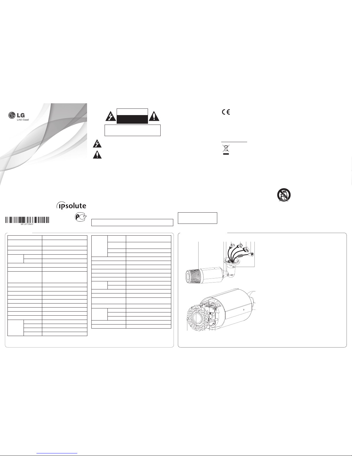
a b c d e f g h
i j k l m
a Lens Cover
b Angle adjuster
Adjust the camera angle.
c Tilt adjuster
Adjust the tilt position.
d Power input terminal
Connects to DC 12 V or AC 24 V power supply using proper cables. This camera must
always be operated DC 12 V or AC 24 V. Certified/Listed Adaptor which comply with LPS.
e AUDIO IN / OUT (Line Level Input/ Output)
f ALARM IN&OUT / ALARM IN&OUT RETURN
Provides physical interface for sensor and Alarm/Relay.
g ETHERNET/PoE Port
Connects to a PC or a network via a hub with a 10 BASE-T/100 BASE-TX cable attached
RJ-45 connector.
NOTE:
Power over Ethernet (PoE) is a technology that integrates power into a standard LAN
infrastructure. It enables power to be provided to the network device, such as a network
camera, using the same cable as that used for network connection. It eliminates the need
for power outlets at the device locations and enables easier application of uninterruptible
power supplies (LPS).
h Pan adjuster
Adjust the pan position.
i IR Sensor
j IR LED
k Video Out connector
Use this jack for checking the picture with portable monitor when install the camera.
l micro SD card slot
Insert the micro SD card.
m RESET button
Push the button more than 3 seconds, this would restore the factory default network
related settings.
Part Names and Functions
Precautions
• Be sure to switch off the unit before
installation and connection.
• The installation should be made by
qualified service personnel or system
installers.
• Do not expose the power and
connection cables to moisture, which
may cause damage to the unit.
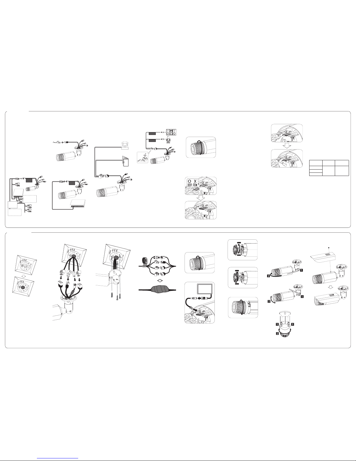
Connecting Network
You can control and monitor the system
via network. With the remote control
(monitoring), you can change the system
configuration or monitor the image via
network. After the installation, check the
network settings for the remote control and
monitoring work.
Connect the IP camera to your network using
a standard RJ-45 network cable as shown
below.
ETHERNET
With PoE
PoE Device
(IEEE802.3af)
Broadband
Service
Broadband
Service
Router
Connecting Power Source
Connect power, using one of the methods
listed below:
To use the power adapter
Connect DC 12 V or AC 24 V power source to
the power input terminal as shown below.
(recommended power adapter is DC 12 V or
AC 24 V/1.5 A or above)
To use the PoE (Power over Ethernet)
device
Connect the PoE cable to the LAN port on the
unit. You must use the “IEEE802.3af” standard
PoE device.
ETHERNET
With PoE
PoE Device
(IEEE802.3af)
NOTE:
If the camera doesn’t work properly after
connecting PoE device, please check if the
PoE device supplies enough power.
Connecting Alarm Device
Alarm terminals are used to connect the
alarm (relay) devices such as sensors, door
switches, etc.
ALARM IN&OUT / ALARM IN&OUT RETURN
(Sensor Input/ Relay Output)
Connect the sensor device and alarm (relay)
device to the alarm terminal. Alarm signal is
outputted at an event occurrence.
Sensor Device
Alarm (relay)
Device
NOTE:
The Photo MOS Relay is rated for 100 mA at
20 V DC or 100 mA at 28 V AC.
Connecting Microphone
and Speaker Device
Optionally connect an active speaker and/or
external microphone with a built-in amplifier.
AUDIO IN
AUDIO OUT
NOTE:
Keep the microphone away from the speaker
to avoid howling.
Using the micro SD card
You can record your surveillance environment
with the micro SD card even if the network is
disconnected condition.
To insert the micro SD card
1. Disassemble the Cover from the main
body by turnining it counterclockwise.
WIDE
TELE
NEAR
FAR
2. Insert the micro SD card carefully as
shown in the following illustrations.
Make sure the micro SD card terminal
position before insert the micro SD card.
Push the back end of the micro SD card
to fix it at the last step.
NOTES:
• Do not use the power too much when
you insert the micro SD card. The micro
SD card may be damaged.
• If you insert the micro SD card in the
wrong position, the micro SD card
may be damaged or it may cause the
malfunction of the micro SD Card Slot.
• Keep the terminal part of the micro SD
card in clean. Be careful the terminal part
of the micro SD card not to dusty.
• As the micro SD card is consumable, the
micro SD card end its days and may be
not able to save data if you use it more
than over certain times. In this case,
replace micro SD card to buy a new one.
Remove the micro SD card
1. Press the back end of the micro SD card
to release the lock condition.
2. Take the micro SD card out carefully from
the camera. It may cause a malfunction
of the micro SD card or the micro SD
card slot if you use the power too much
at lock status.
CAUTION:
• If you install the micro SD card on the
camera and remove with the micro SD
card condition indicator lights on, you
must unmount the micro SD card by
using the [SD Card > Configuration >
Disk Management > Unmount] menu.
The micro SD card data is compromised
or the camera may not operate normally,
if you remove the card without use
[Unmount] function.
• LG Electronics is not responsible for
deleted data caused by user mishandling
when you insert or remove the micro
SD card.
Recommended the micro SD card
specication
Maker Capacity
Block Size
(FAT 32)
LG
Less than
32 GB
32 kbyteSandisk
Transcend
NOTE:
Speed of reading and writing more than
10 MB/Sec. (Class 6)
Connection
Follow the instructions below to ceiling or
wall mount the camera.
Mounting the Camera
1. Using a template as a guide, make a hole
through the ceiling.
2. Connect the cables to the cable jacks of
the camera body.
3. Install the camera by using M3 Tapping
screws to fix it on the ceiling.
Connecting Waterproof
processing of cable
Surely use the Butyl tape.
1. Connect the cables.
2. Bind the cables together with Butyl tape.
WARNING:
• The cables are not waterproofed
completely. So seal the tube ends and
the portions between cable cores as well
as connecting portions with Butyl tape.
• If not using the Butyl tape, it may cause
water absorption from a gap and finally
condensation and water leakage.
Adjust the Focus
You should adjust the focus as shown below
steps.
1. Disassemble the Cover from the main
body by turnining it counterclockwise.
WIDE
TELE
NEAR
FAR
2. Connect the portable monitor to the
video jack using the test monitor cable.
Test Monitor
Cable
3. Set the zoom level of the lens.
WIDE
TELE
NEAR
FAR
4. Set the focus of the lens correctly.
NEAR
FAR
5. Close and tighten the Cover to the main
body by turning it clockwise.
WIDE
TELE
NEAR
FAR
Adjust the camera
position
You should adjust the camera angle position
as shown below illustration. Adjust the
camera angle position by following step a
and b.
1. Adjust the Pan.
2. Adjust the Tilt.
3. Adjust the Angle.
Assemble the Sunshield
Adjust the position of the Sunshield, then
assemble the Sunshield.
Installation
 Loading...