

OWNER'S MANUAL
Network Dome Camera
Please read this manual carefully before operating
your set and retain it for future reference.
MODEL
LNP2810 series
LNP2810T series
AB28
CAUTION
RISK OF ELECTRIC SHOCK
DO NOT OPEN
CAUTION: TO REDUCE THE RISK OF ELECTRIC SHOCK
DO NOT REMOVE COVER (OR BACK)
NO USER-SERVICEABLE PARTS INSIDE
REFER SERVICING TO QUALIFIED SERVICE PERSONNEL.
This lightning flash with arrowhead symbol within an equilateral triangle is
intended to alert the user to the presence of uninsulated dangerous voltage
within the product’s enclosure that may be of sufficient magnitude to
constitute a risk of electric shock to persons.
The exclamation point within an equilateral triangle is intended to alert the
user to the presence of important operating and maintenance (servicing)
instructions in the literature accompanying the product.
FCC WARNING: This equipment may generate or use radio frequency energy. Changes or
modifications to this equipment may cause harmful interference unless the modifications are
expressly approved in the instruction manual. The user could lose the authority to operate this
equipment if an unauthorized change or modification is made.
REGULATORY INFORMATION: FCC Part 15
This equipment has been tested and found to comply with the limits for a Class A digital device,
pursuant to Part 15 of the FCC Rules. These limits are designed to provide reasonable protection
against harmful interference when the equipment is operated in a commercial environment.
This equipment generates, uses, and can radiate radio frequency energy and, if not installed
and used in accordance with the instruction manual, may cause harmful interference to radio
communications.
Operation of this equipment in a residential area is likely to cause harmful interference in which
case the user will be required to correct the interference at his own expense.
• A suitable conduit entries, knock-outs or glands shall be provided in the cable entries of this
product in the end user.
• Caution: Danger of explosion if battery is incorrectly replaced. Replaced only with the same or
equivalent type recommended by the manufacturer. Dispose of used batteries according to
the manufacturer’s instructions.
• Holes in metal, through which insulated wires pass, shall have smooth well rounded surfaces
or shall be provided with brushings.
This Class A digital apparatus complies with Canadian ICES-003.
Cet appareil numérique de la classe A est conforme à la norme NMB-003 du Canada.
Warning
• Do not install this equipment in a
confined space such as a bookcase or
similar unit.
• Wiring methods shall be in accordance
with the National Electric Code, ANSI/
NFPA 70.
• This is a class A product. In a domestic
environment this product may cause
radio interference in which case the
user may be required to take adequate
measures.
• To reduce a risk of fire or electric shock,
do not expose this product to rain or
moisture.
Caution
• This installation should be made by a
qualified service person and should
conform to all local codes.
• To avoid electrical shock, do not open
the cabinet. Refer servicing to qualified
personnel only.
• The apparatus shall not be exposed to
water (dripping or splashing) and no
objects filled with liquids, such as vases,
shall be placed on the apparatus.
To disconnect power from mains, pull
out the mains cord plug. When installing
the product, ensure that the plug is easily
accessible.
LG Electronics hereby declares
that this/these product(s) is/are
in compliance with the essential
requirements and other relevant
provisions of Directive 2004/108/
EC and 2011/65/EU.
Contact office for compliance
of this product:
LG Electronics Inc.
EU Representative, Krijgsman
1,1186 DM Amstelveen, The
Netherlands
Disposal of your old appliance
1. When this crossed-out
wheeled bin symbol is
attached to a product
it means the product is
covered by the European
Directive 2002/96/EC.
2. All electrical and electronic
products should be
disposed of separately from
the municipal waste stream
via designated collection
facilities appointed by the
government or the local
authorities.
3. The correct disposal of
your old appliance will help
prevent potential negative
consequences for the
environment and human
health.
4. For more detailed
information about disposal
of your old appliance,
please contact your city
office, waste disposal
service or the shop
where you purchased the
product.
EEE Compliance with Directive.
(for Turkey only)
Important Safety Instructions
1. Read these instructions.
2. Keep these instructions.
3. Heed all warnings.
4. Follow all instructions.
5. Do not use this apparatus near water.
6. Clean only with dry cloth.
7. Do not block any ventilation openings.
Install in accordance with the
manufacturer’s instructions.
8. Do not install near any heat sources such
as radiators, heat registers, stoves, or other
apparatus (including amplifiers) that
produce heat.
9. Do not defeat the safety purpose of
the polarized or grounding-type plug.
A polarized plug has two blades with
one wider than the other. A grounding
type plug has two blades and a third
grounding prong. The wide blade or the
third prong are provided for your safety.
If the provided plug does not fit into
your outlet, consult an electrician for
replacement of the obsolete outlet.
10. Protect the power cord from being
walked on or pinched particularly at
plugs, convenience receptacles, and the
point where they exit from the apparatus.
11. Only use attachments/accessories
specified by the manufacturer.
12. Use only with the cart, stand, tripod,
bracket, or table specified by the
manufacturer, or sold with the apparatus.
When a cart is used, use caution when
moving the cart/apparatus combination
to avoid injury from tip-over.
13. Unplug this apparatus during lightning
storms or when unused for long periods
of time.
14. Refer all servicing to qualified service
personnel. Servicing is required when
the apparatus has been damaged in any
way, such as power-supply cord or plug
is damaged, liquid has been spilled or
objects have fallen into the apparatus, the
apparatus has been exposed to rain or
moisture, does not operate normally, or
has been dropped.
Handling of the unit
Be careful not to spill water or other liquids on
the unit. Be cautious not to get combustible or
metallic material inside the body. If used with
foreign matter inside, the camera is liable to
fail or to get cause of fire or electric shock.
• Remove dust or dirt on the surface of the
lens with a blower.
• Use a dry soft cloth to clean the body. If it
is very dirty, use a cloth dampened with a
small quantity of neutral detergent then
wipe dry.
• Avoid the use of volatile solvents such
as thinners, alcohol, benzene and
insecticides.
They may damage the surface finish and/
or impair the operation of the camera.
Operating and storage
location
Avoid viewing a very bright object (such as
light fittings) during an extended period. Avoid
operating or storing the unit in the following
locations.
• Extremely hot or cold places (operating
temperature -20 °C to 50 °C, however, we
recommend that the unit be used within
a temperature range of 0 °C to 45 °C)
• Damp or dust place
• Places exposed to rain
• Places subject to strong vibration
• Close to generators of powerful
electromagnetic radiation such as radio
or TV transmitters.
Specifications
Item LNP2810 Series LNP2810T Series
Image Sensor 4.5 mm (1/4 type) CMOS
Lens x28 Zoom, f = 3.5 mm to 98 mm
Resolution (Maximum) Up to 1280 x 720
Day&Night ICR Day & Night (Day / Night / Auto)
Mininum
Illumination
White Balance Auto / ATW / One Push / Manual
Shutter Speed 1/160 to 1/10 000
Iris Auto / Manual
BLC Off / WDR/ BLC
3D-DNR OFF / LOW / MIDDLE / HIGH
AGC OFF / LOW / MIDDLE / HIGH
Privacy Mask 8 Masks
Multi-Streaming Dynamic Profile (Up to 7)
ROI (Region of Interest) Support
Video Out 1xBNC
Frame Rate (Maximum) 30 fps @ 720p
Bit Rate 256 kbps to 10 240 kbps
Auto Tracking No Support Support
Audio Compression G.711, G726
Audio In/Out 1/1
Sample Rate 8 KHz
Audio Bit Rate G.711: 64 kbps, G.726: 24 kbps, 32 kbps
Ethernet 10/100 Ethernet
Color 0.8 lx (F1.5, Sens-up off ), 0.16 lx (F1.5, Sens-up x32)
B/W 0.01 lx (F1.5, Sens-up off ), 0.000 1 lx (F1.5, Sens-up x32)
Protocol IPv4 and IPv6 TCP/IP, UDP, HTTP, HTTPS, RTP, RTSP, DHCP, ICMP
IPv4 FTP, SMTP, NTP, ARP, SNMP v1/v2c/v3, DDNS(LG)
Open Protocol ONVIF 2.2 Profile S, PSIA 1.1
Remote S/W LVi510, Mobile Application (IPhone, Android, iPad)
Pan/Tilt Travel Range Pan:360˚(Endless), Tilt:180˚
Speed Preset 500˚/second
Jog 0.1˚ to 360˚/second
Preset 256
Pattern 4 Patterns (760 command/Pattern)
Auto Pan 2 points to 8 points
Group 10 Groups (8 presets/Group)
Sensor /
Alarm
Misc. Mount Accessory Mount Adaptor
Sensor 4 Inputs, Photo-Coupler Input
Alarm 2 Relay Outputs, Max Load : DC 30 V 1 A / AC 125 V 0.3 A
IP Module Reset
Terminal
Material Aluminum, Plastic sunshield
Rated Power PoE+ / AC 24 V (49 W)
Waterproof IP66, IK10
Fan Always ON
Operation
Temperature
Weight 3.3 Kg
Dimension (Ø x H) 195 mm x 229 mm
Support
-20˚C to 50˚C
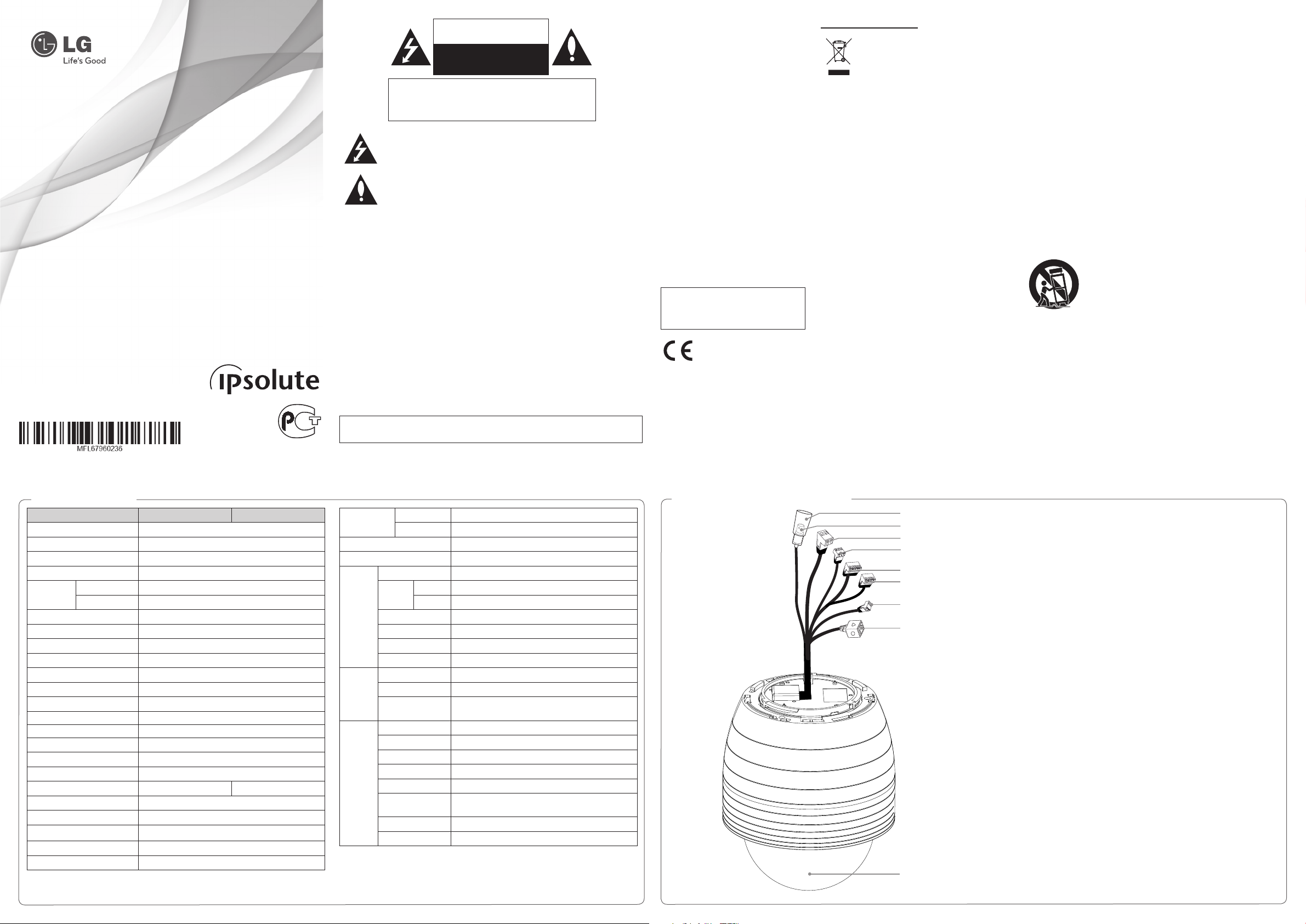
Part Names and Functions
a
b
c
d
e
f
g
h
i
a BNC connector cover cap
b Video output BNC connector
c Power input terminal
This camera must always be operated AC 24 V.
Certified/Listed Adaptor which comply with LPS.
d AUDIO IN / OUT (Line Level Input / Output)
Input for a mono microphone, or a line-in mono signal.
Connect to an active speaker with a built-in amplifier.
e Data Input Terminal
Input data terminal for alarm signal.
f Data O utput Terminal
Output data terminal for alarm signal.
g IP Reset
h ETHERNET Port
Connects to a PC or a network via a hub with a 10 BASE-T/100 BASE-TX cable attached
RJ-45 connector.
i Dome Cover
Accessories
• Software Installation CD
• Cover adaptor
• Mount adaptor
• RJ-45 Cable
• Wrench
• M3 SAMS Screws
Connection Using the SD Card
Connecting Display device
The video signal connection between the
camera and the monitor.
ALARM input connection
Connect sensor and alarm devices to
corresponding terminals accordingly.
A
B
C
D
E
Alarm device
Alarm device
Alarm device
Alarm device
Terminal BlockTerminal Plug
Description Color
A ALARM IN 1 Brown
B ALARM IN 2 Red
C ALARM IN COM Black
D ALARM IN 3 Orange
E ALARM IN 4 Green
ALARM output connections
A
B
C
D
Terminal Plug
Description Color
A ALARM OUT 1A Blue
B ALARM OUT 1B Violet
C ALARM OUT 2A Gray
D ALARM OUT 2B White
CAUTION:
Output specifications are lowactive, opencollector and a drive capacity of DC 30 V 1
A/ AC 125 V 0.3 A. Connecting the alarm out
incorrectly may cause damaging the camera.
Alarm device
Alarm device
Terminal Block
Connecting IP Reset
Connect the 2 (IP Reset) and 3 (GND) to
reset the IP address as shown below.
A
B
Description Color
A IP Reset Pink
B GND Yellow
IP Reset
GND
Terminal BlockTerminal Plug
Connecting Network
Connect the IP camera to your network
using a standard Terminal block as shown
below.
Router
Connecting power source
Connect a AC 24 V or PoE+ power source to
the power input terminal as shown below.
(Recommended power adaptor is AC 24 V/3
A or above.)
NOTES:
• In case of connecting both AC 24 V and
PoE+, PoE+ has a priority.
• Do not connect the power source AC 24 V
and PoE at once.
AC 24 V
or
or
PoE+
Connecting Microphone and
Speaker Device
Optionally connect an active speaker and/or
external microphone with a built-in amplifier.
NOTE:
Keep the microphone away from the speaker
to avoid howling.
You can record your surveillance environment with the SD card even if the network is disconnected
condition.
To insert the SD card
1. Remove the dome cover.
2. Insert the SD card carefully as shown in the following illustrations. Make sure the SD
terminal position before insert the SD card. Push the back end of the SD card to fix it at the last
step.
NOTES:
• Do not use the power too much when you insert the SD card. The SD card may be
damaged.
• If you insert the SD card in the wrong position, the SD card may be damaged or it may cause
the malfunction of the SD Card Slot.
• Keep the terminal part of the SD card in clean. Be careful the terminal part of the SD card
not to dusty.
• As the SD card is consumable, the SD card end its days and may be not able to save data if
you use it more than over certain times. In this case, replace SD card to buy
a new one.
card
Remove the SD card
1. Press the back end of the SD card to release the lock condition.
2. Take the SD card out carefully from the camera. It may cause a malfunction of the SD
or the SD card slot if you use the power too much at lock status.
CAUTION:
• If you install the SD card on the camera and remove with the SD card condition indicator
lights on, you must unmount the SD card by using the [SD Card > Configuration > Disk
Management > Unmount] menu. The SD card data is compromised or the camera may
not operate normally, if you remove the card without use [Unmount] function.
• Do not insert Micro SD card to SD card adapter. It is recommended to use a standard SD
card.
• Insert the SD card before install the camera.
• LG Electronics is not responsible for deleted data caused by user mishandling when you
insert or remove the SD card.
card
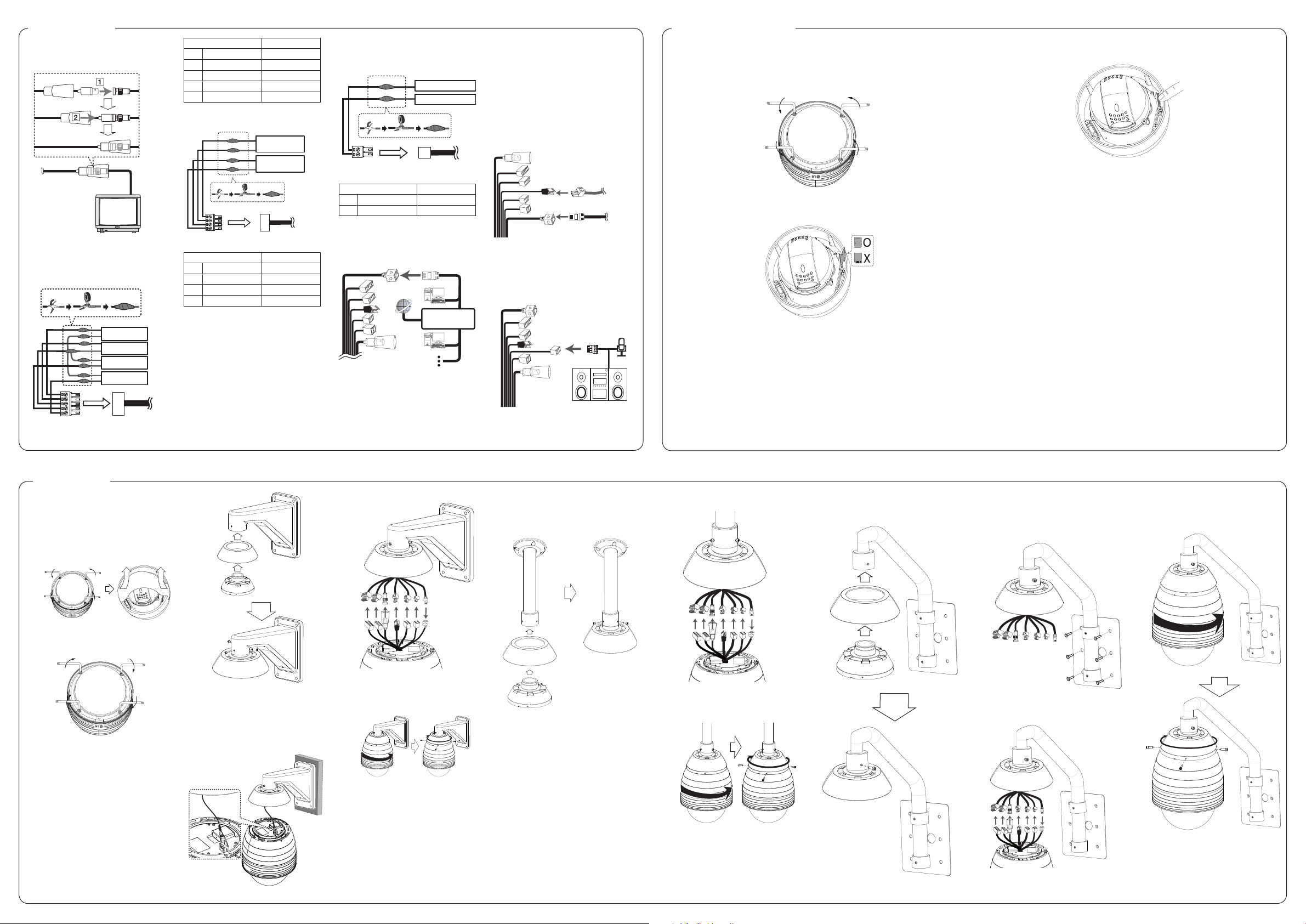
Installation
Precautions
• Remove the dome cover carefully to
prevent falling.
• Before using the camera, remove the
protection tape. Loosen the screws using
the wrench and remove the dome cover
as shown below.
• Align the s mark of the dome cover
and LG logo of the camera assembly for
proper camera orientation.
Wall mount (optional)
Install the camera by the following order.
1. Install the wall mount assembly as
shown below.
2. Drill a hole on the wall where you want
to install the pipe. Pass the connection
cable through the wall mount assembly
so that they hang down.
3. Connect the safety cable to the camera
in order to prevent a camera from falling.
4. Connect the cables to the camera jack.
5. Assemble the camera to the mounting
adaptor by turning it clockwise. Tighten
the M3 SAMS Screws and then align the
cover adaptor and main body.
Pandent mount (optional)
Install the camera by the following order.
1. Install the pandent mount assembly as
shown below.
2. Drill a hole on the wall where you want
to install the pipe. Pass the connection
cable through the pendant mount
assembly so that they hang down.
3. Connect the safety cable to the camera.
4. Connect the cables to the camera jack.
5. Assemble the camera to the mounting
adaptor by turning it clockwise. Tighten
the M3 SAMS Screws and then align
the cover adaptor and main body.
Parapet mount (optional)
1. Install the parapet mount assembly as
shonw below.
2. Drill a hole on the wall where you
want to install the parapet. Pass the
connection cable through the parapet
mount assembly so that they hang
down.
3. Connect the safety cable to the camera.
4. Connect the cables to the camera jack.
5. Assemble the camera to the mounting
adaptor by turning it clockwise. Tighten
the M3 SAMS Screws and then align the
cover adaptor and main body.
 Loading...