

LG LNU5100R series, LNB3100 series, LND5100R series, LNV5100R series, LND5100 series Owner's Manual
...
1302 (V1.4)
MODEL
LNB5100 series
LNB3100 series
LND5100 series
LND3100 series
LNV5100 series
LNU5100R series
LND5100R series
LNV5100R series
Please read this manual carefully before operating your set and retain it for future reference.
OWNER'S MANUAL
High Definition Network Camera

2
Contents
Introduction ................................................................................... 3
Operation and settings ................................................................. 4
Before using the system .....................................................................4
Recommended PC Requirements ...................................................4
Accessing the LG IP device.................................................................5
LG Smart Web Viewer Overview ......................................................6
Conguration menu overview ..........................................8
Conguring the LG Network Camera Device ..............................8
Accessing the Conguration menu .................................8
System settings .......................................................................9
Audio & Video settings ......................................................14
Network settings ................................................................. 24
User settings ......................................................................... 29
Event settings ....................................................................... 30
OSD Menu Setup (Optional)...........................................................40
General Operation .............................................................. 42
Exposure settings ................................................................42
White Balance settings ...................................................... 44
Day/Night settings .............................................................45
3D-DNR setting .................................................................... 45
Privacy setting ......................................................................46
Special menu settings ....................................................... 47
SCENE mode setting (Optional) ..................................... 49
Reset setting ......................................................................... 50
Reference .....................................................................................51
Troubleshooting .................................................................................51
Open source software notice ......................................................... 54
Specications.......................................................................................55

Introduction 3
The LG Network Camera is designed to use on an Ethernet network and must be assigned an IP address to make it accessible.
This manual contains instructions on how to install and manage the LG Network Camera in your networking environment. Some knowledge
of networking environments would be beneficial to the reader.
Should you require any technical assistance, please contact authorized service center.
Features Chart
This table shows the differences between the models.
Item LNB5100 LND5100 LNB3100 LND3100 LNV5100 LNU5100R LND5100R LNV5100R
VA Yes Yes No No Yes Yes Yes Yes
Audio Yes Yes No No Yes Yes Yes Yes
Sensor&Relay Yes Yes No No Yes Yes Yes Yes
OSD Control Yes Yes Yes Yes Yes No No No
OSD
ALC2 Yes Yes Yes No Yes Note Note Note
SCENE Mode Yes Yes No No Yes Yes Yes Yes
Note:
Model LNU5100R, LND5100R and LNV5100R has been added the function that limit the Max Shutter Speed same as ALC2.
Introduction

4 Operation and settings
Operation and settings
Before using the system
• Before using the LG IP device make sure the connections are
correct and verify whether proper power supply is used.
• Check the connections of the LG IP device for the correct
conditions.
• Check that the LG IP device is(are) connected to the network and
that power is supplied.
• Once the connections are made you need to install the LG client
program to the PC from which you want to access the device.
The LG Smart Web Viewer program is automatically installed
when you connect the LG IP device.
The LVi510 and the LG Smart Web Viewer program are the
network program of the LG Video Server and the LG IP cameras.
• To view streaming video in Internet Explorer, set your browser
to allow ActiveX controls. If you find this message “This website
wants to install the following add-on: ‘IPCam_Streamer.cab’ from
‘LG ELECTRONICS INC’”, Click the yellow bar and install LG Smart
Web Viewer Program on your computer. Please set your browser
zoom level to 100%.
• The Layouts and the Live view pages may differ with different OS
(Operating Systems) and Web Browsers.
• Care needs to be taken not to run any other applications when
the Client Program is running as it may cause memory shortage.
Recommended PC Requirements
The LG IP device can be used with most standard operating systems
and browsers.
Items Requirements
Operating System
Windows XP Professional,
Windows VISTA, Windows 7
CPU
Intel Core2 Quard Q6700 (2.66 GHz) or
above
Web Browser
Microsoft Internet Explorer above the
version 7.0 and below the version 9.0.
DirectX
DirectX 9.0c (Windows XP), DirectX 11
(Windows VISTA, Windows 7) or above
Memory 2 GB or above RAM
Graphics Card 256 MB or above Video RAM
Resolution 2048 x 1536 (with 32 bit color) or higher

Operation and settings 5
Accessing the LG IP device
You can access the LG IP device by following the below steps.
1. Install LVi510 Program
It recommended to use LVi510 surely.
2. Discover the LG IP device using the IP Utility
The IP Utility can automatically discover and display LG IP
devices on your network.
The IP Utility shows the MAC address, IP address, Model
name and so on.
Note:
The computer running the IP Utility must be on the same
network segment (physical subnet) as the LG IP device.
2.1 Run the IP Utility program.
2.2 Click the [Search] button or select the [Search] option
in the Device search menu.
After a few seconds the found LG IP devices gets
displayed in the IP Utility window.
3. Logging in to the LG Smart Web Viewer
3.1 Run the IP Utility and find the LG IP devices.
3.2 When the LG IP devices appear in the IP Utility
window, double-click IP address or right click on the
same IP address and select “Connect to Web Page”
to start the LG Smart Web Viewer. When accessing
the LG Smart Web Viewer, the authentication dialog
appears on the screen.
3.3 Enter the user name and password. (Note that the
default administrator user name and password are
“admin”.)
Note:
Default password must be changed for security after
initial connection.
3.4 Click the [OK] button and then the LG Smart Web
Viewer is displayed in your browser.
Notes:
• You can also access the LG Smart Web Viewer as shown
below.
3.1 Start your Web browser.
3.2 Enter the IP address of the LG IP device in the address
bar of the browse.
3.3 Enter the user name and password set by the
administrator.
3.4 Click the [OK] button and then the LG Smart Web
Viewer is displayed in your browser.
• The LG Smart Web Viewer needs more time to display it
according to the network conditions.
• If the login window is not displayed, check the pop-up
blocker. If you set the pop-up blocker, the login window
is not displayed. You must allow the pop-ups.
• If you connect the LG Smart Web Viewer for the first time,
the Security Warning window is displayed to install the
LG Smart Web Viewer program. You must install the LG
Smart Web Viewer program for using the LG IP device.
• If your computer or network is protected by a proxy or
firewall, the proxy or firewall settings can prevent the LG
Smart Web Viewer program. Change the proxy or firewall
settings to activate the LG Smart Web Viewer program.
6 Operation and settings
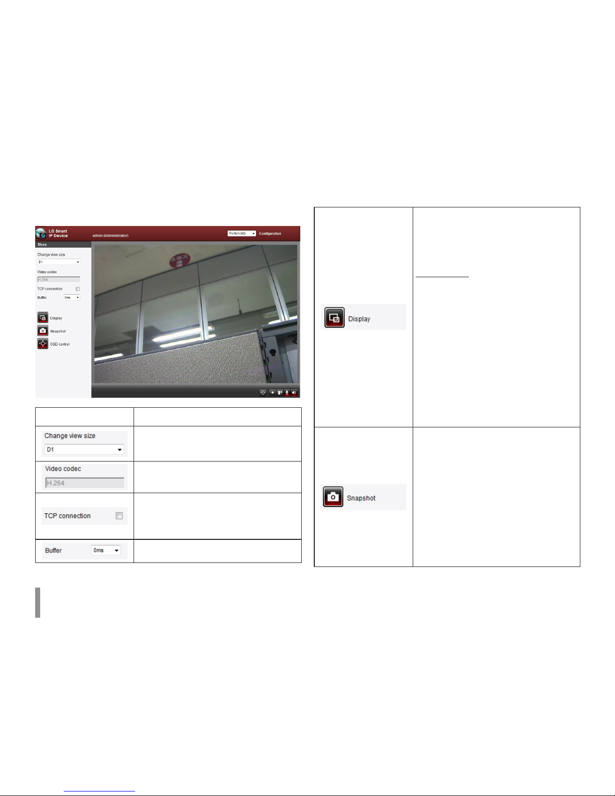
LG Smart Web Viewer Overview
Item Description
Select the video image size from the
drop-down list.
The initial view size is set to D1.
Displays the current video codec of the
selected video stream. .
Check this option as the network
connection type (TCP or UDP). If you
check it, the client connects to the server
using TCP connection.
Select buffering time of live stream.
Click to display the check box of
[Hostname], [Framerate] and [Bitrate]
options. [Display] is displayed on left
top of the live view window in order of
selecting options.
Video Analysis
> Hide: Video Analysis display
function is not in use.
> SVA: Displays the Smart Video
Analysis function to the live view
window.
> MD: Displays the Motion
Detection function to the live
view window.
Note:
When you use the DPTZ function, all
of Display function is deactivated for
a while.
Click to save the current image in JPEG
format on your computer.
1. Click the [Snapshot] button and then
the Snapshot window is displayed.
2. Click the [Save] button in the
Snapshot window.
3. Enter the file name (JPEG format) and
select the folder to save it.
4. Click the [Save] button to confirm it.
5. Click the [Close] button in the
Snapshot window to close it.
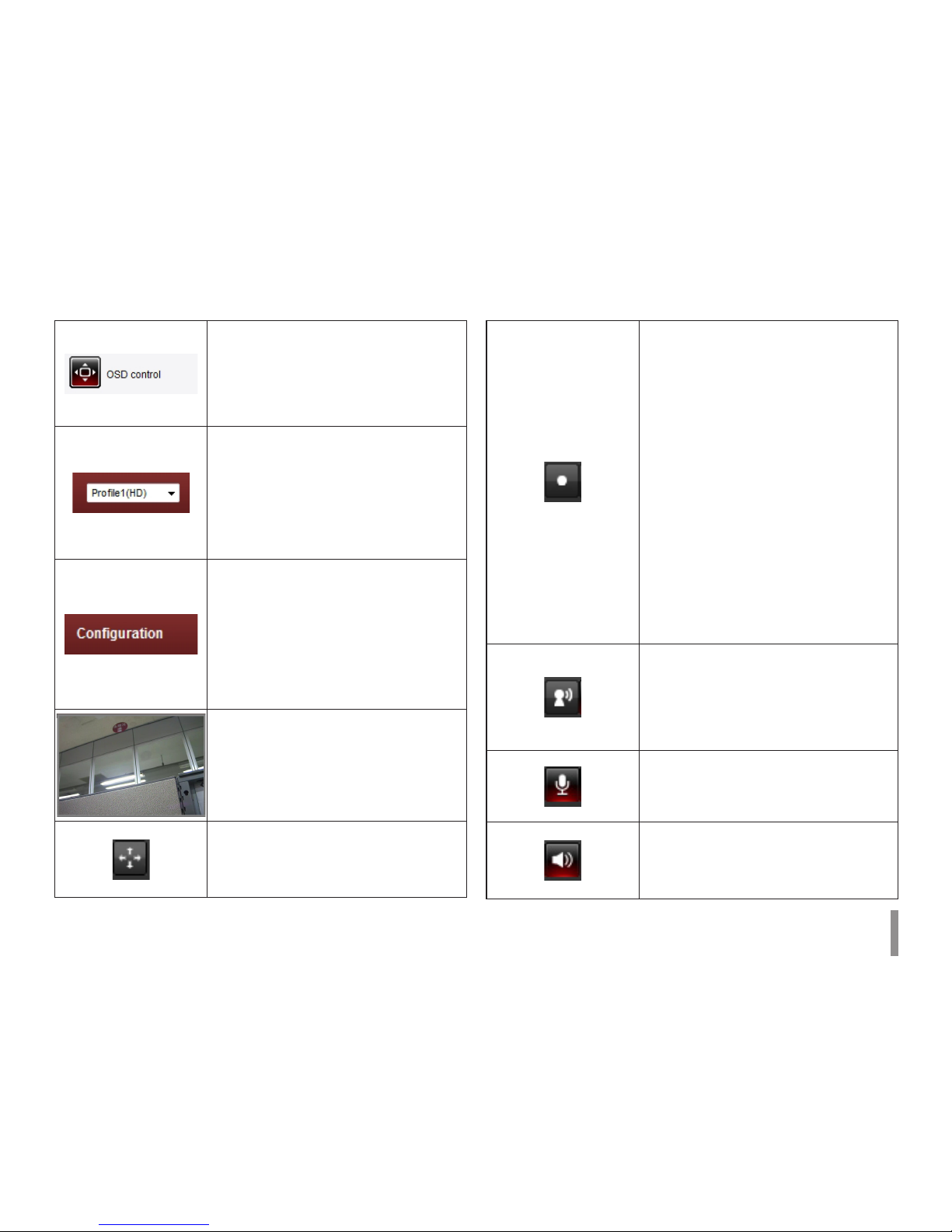
Operation and settings 7
Displays the Camera OSD control
window. Use these buttons to setup the
Camera. This button does not appear on
the screen if the login is other than the
administrator. The option depends on
the model.
Select the video stream. From the Live
view drop-down list, select the desired
video image source.
Note:
You can set the stream configurations
independently. This would facilitate the
user to set the live view at his comfort.
Provides all the necessary tools
for setting up the device to your
requirements. The user will need
administrator level to do this.
Note:
If you want to exit the Configuration
menu, select one of the video stream in
the Live view drop-down list.
Displays the current surveillance live
screen. You can monitor the camera
image on the live view window of the LG
Smart Web Viewer.
Click this button and drag the area to use
PTZ function. Right-clicking the screen
will bring up the previous magnification.
(Color icon: On, Gray scale icon: Off.)
1. Click this button to open the folder
browse window. Click the button
again in next time, video is recorded
automatically without selection of
folder.
Note:
If you want to change the folder,
move to other pages or press the
refresh button.
2. Recording button is activated and
recording will be started.
Note:
If recording exceed the time(1 hour)
or size limit (1 GB), recording is
stopped automatically with warning.
3. To stop the recording, click this
button during the recording.
Click this button to connect or
disconnect the audio communication
between the LG IP device and the
connected PC. The option depends on
the model.
(Color icon: On, Gray scale icon: Off.)
Click this button to switch the
microphone off and on for the computer.
The option depends on the model.
(Color icon: On, Gray scale icon: Off.)
Click this button to switch the sound off
and on, for the speaker of the computer.
The option depends on the model.
(Color icon: On, Gray scale icon: Off.)
8 Operation and settings
Conguration menu overview
The following table shows the list of menu items.
The configuration images are different from each model.
Main Menu Sub Menu
System
Version
Date & Time
Maintenance
Storage Option
Text Overlay
Log & Report
Language
Audio & Video
Camera
Stream
Audio Option
Network
Basic
RTP stream
TCP/IP
DDNS
IP filtering
SNMP
User Basic
Event
Event server
Sensor & Relay Option
Motion detect
Smart analytics Option
Triggered Event
Scheduled Event
Conguring the LG Network Camera
Device
The features and options of the LG IP camera are configured
through the Configuration menu.
Only administrator-level users have permission to access the
Configuration menu.
Accessing the Conguration menu
Click the [Configuration] button to display the LG Smart Web Viewer
configuration window.
Warning
The Configuration setup should be made by qualified service
personnel or system installers.
Operation and settings 9
System settings
Version
Displays the current Model Name and Software version.
Date & Time
Time zone
Set the time difference from GMT in the area where the IP device
is installed. Select the time zone in the area where the IP device is
installed from the drop down list.
Time mode
> Synchronize with NTP Server: Select if you want to
synchronize the IP device’s date and time with those of the
time server called NTP (Network Time Protocol). Specify the
NTP server’s name. Click the [Test] button for connection test
to the server.
> Synchronize with personal computer: Select if you want
to synchronize the IP device’s date and time with your
computer.
> Synchronize manually: Select if you want to set the IP
device’s date and time manually. Select the year, month and
date by clicking the calendar button. Set hour, minutes and
seconds in the edit boxes.
Notes:
• When system reboot after time setting, time of system
could be delayed. If you set the time correctly, set the
[Synchronize with NTP server] option.
• Refer to NTP configuration as operation system of
the Recording Server when the Recording Server use
recording function and NTP server.
Server time
> Server time: Displays the current date and time of the IP
device.
• Save: Click this button to confirm the settings.
10 Operation and settings
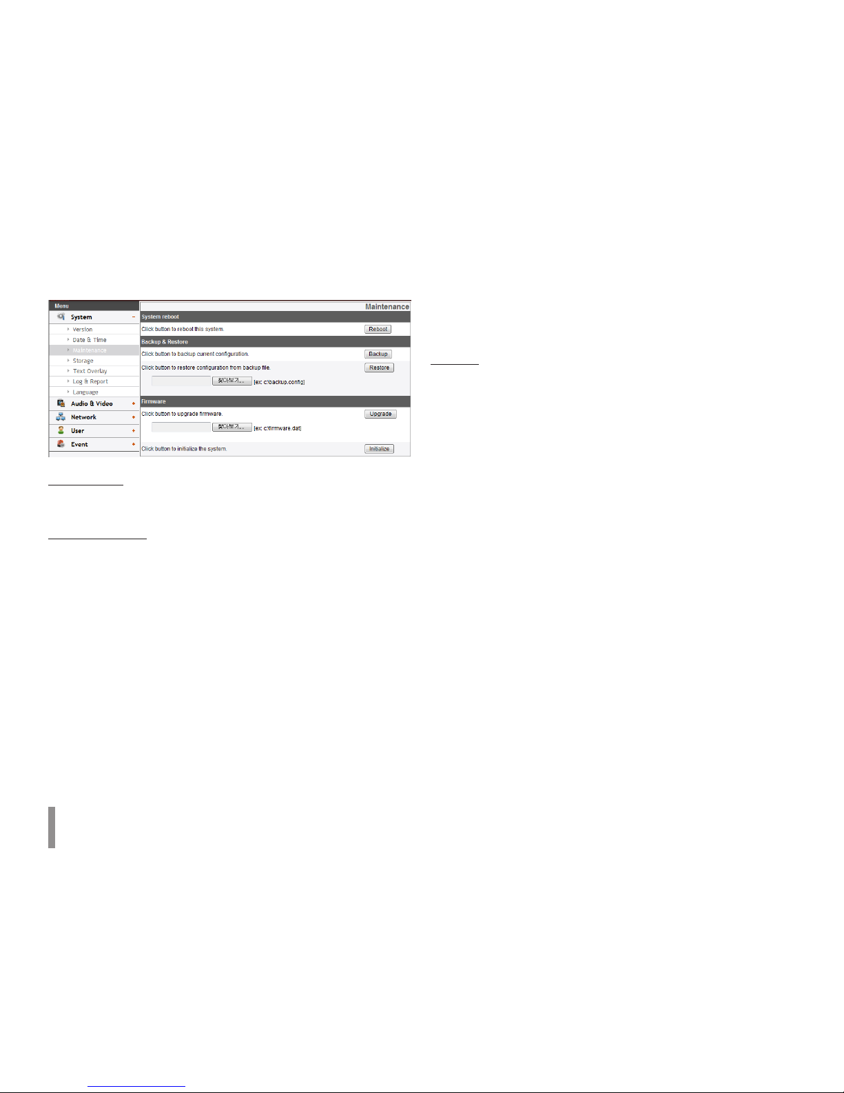
Maintenance
System reboot
Click the [Reboot] button to restart the IP device. It takes some
minutes for the IP device to start again.
Backup and restore
> Backup: To take a backup all of the settings. If necessary, it
make possible to return to a backup configuration.
1. Click the [Backup] button.
2. Click the [Save] button.
3. Follow the instructions on the browser to specify the
folder.
4. Click the [Save] button to save the settings.
> Restore:
1. Click the [Browse] button.
2. Find and open the file in which the configuration setting
data is stored.
3. Click the [Restore] button and the system settings will be
restored and reboot the system.
Note:
Backup and Restore can happen on IP device having the
same version of firmware. This feature is not intended for
multi-configurations or for firmware upgrades.
Firmware
> Upgrade
1. Click the [Browse] button.
2. Find and open the firmware file.
3. Click the [Upgrade] button to update the firmware.
Note:
When you upgrade the system, it may take some minutes
to be done. Do not close the browser while the upgrade
is in progress. If you close the browser, it may cause a
malfunction. You should wait until the confirmation window
is displayed. When the upgrade is finished, the confirmation
window will be displayed.
> Initialize: The [Initialize] button should be used with caution.
Clicking it will return all of the IP device’s settings to the
factory default values. Except for the Network settings, PTZ
Protocol and Preset settings. (The option depends on the
model.)
Operation and settings 11
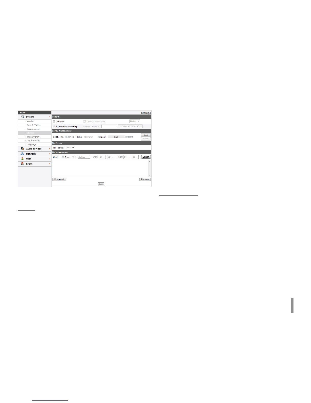
Storage (Optional)
Note:
SD Card function may not be supported in specific countries.
Genernal
> Overwrite: If the micro SD card has insufficient space and
this option will be activated. It will overwrite the oldest data.
> DiskFull Notification: Sends an warning e-mail to the SMTP
server when the micro SD card has fully recorded. Select the
SMTP server from the drop-down list. You should register the
SMTP server on the Event server setting to set this function.
> Network Failure Recording: Select the check box to activate
the micro SD card recording function. If the system does
not work with recording server, the system will record the
data to the micro SD Card. When the system connect to the
recording server again, the recorded data of the micro SD
card will transfer to the recording server automatically.
> Recording Server IP: Enter the recording server IP.
> Set as NTP server IP: Click this button to use the entered
Recording Server IP as the NTP server IP.
Notes:
• The recorded file name is made automatically as the
“[Created date of the file]_[GMT Recording Time]+(-)
[Value of the Local Time minus GMT Time (Second)]_[Use
or not of the Daylight saving time(N/D)][Stream index]
[DeleteFlag].DAT” type.
• If the capacity of the SD card remains less than 200 MB,
stop recording or overwrite new file after delete old one
as [Overwrite] setting. The overwritten file can not play
or may malfunction when you download.
• Recorded file on the SD card, is recording 1 frame per
second when set video codec to MJPEG.
Device Management
> Using the micro SD card
1. Insert the micro SD card carefully to the micro SD card
slot of the camera.
2. Click the [Mount] button. If the micro SD card is mounted
to the system correctly, the [Mount] button will be
changed to the [Unmount] button.
3. Displays the information of the[Disk ID], [Status],
[Capacity] options.
Notes:
• When the micro SD card is mounted, you should format
the micro SD card. After the micro SD card format is
finished, you should click the [Mount] button to use it.
• When you use the micro SD card format function, it may
not progress immediately. In this case, you should try it
again after waiting a few minutes.

12 Operation and settings
> Remove the micro SD card
1. Click the [Unmount] button. If the micro SD card is
unmounted from the system correctly, the [Unmount]
button will be changed to the [Mount] button.
2. Remove the micro SD card from the micro SD card slot of
the camera.
Note:
When you use the Unmount function, it may not progress
immediately. Operations such as recording of the system and
reading of data are required stop time before the Unmount
function is activated. You should try it again after waiting a
few minutes.
File Format
> File Format: You can selects the Recording File Format(AVI
or DAT). Recording, Search and Download are available
according to the setting.
Notes:
• SD Recording or FTP(Video) Sending Format are set
according to the setting. When you select to AVI, [Auto
Recording function] may not be activated in case of
network error.
• IP Camera’s time will be appeared in players based on
DirectShow such as Windows Media Player and MPlayer.
File Management
Displays the recorded file of the micro SD card on the list. Click the
[Search] button to display the recorded file. The list will be updated
when you click the [Search] button.
> To view the recorded file of the micro SD card
1. Select the search option.
- All: Search the all recorded files in the micro SD card.
- Some: You can set the search condition by using the
date and time options.
2. Click the [Search] button and then the search result is
displayed on the list.
> Download: You can download the recorded data of the
list to your PC. Select a recorded file on the list and click
the [Download] button. The two confirmation window
is displayed. You should download the all files that the
recorded file(*.DAT) and information file(*.INFO). You can
download as AVI file according to File format.
Notes:
• It is recommended to deactivate the [Overwrite] function
before you download the file. When [Overwrite] function
is activated, the downloading file might be overwritten,
if the micro SD card has insufficient space.
• The downloaded file can be played by using the LG File
player.
> Remove: Delete file from the SD card.
• Save: Click this button to confirm the settings.
Operation and settings 13
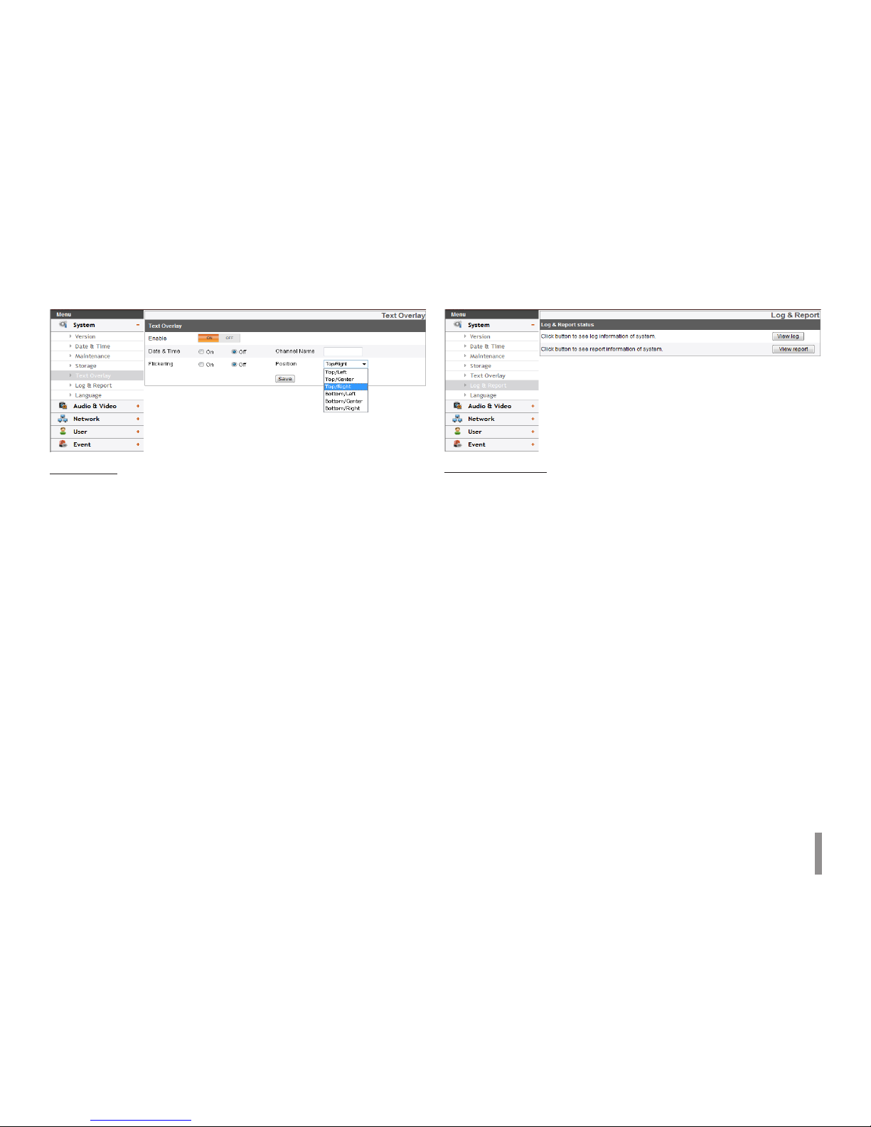
Text Overlay
Text Overlay
> Enable: Set to ON or OFF. Setup menu is appeared when
selects ON.
> Date & Time : Select the ON to display time and date of
Client PC.
> Channel Name: Enter the channel name you want to use.
You type the Channel Name, it will be displayed whether you
select the ON or OFF.
> Flickering: Set to On or OFF.
> Position: You can designate the position of text from drop
down list.
• Save: Click this button to confirm the settings.
Log & Report
Log & Report status
The System log provides a summary of the status of the IP device.
The unit records the data of the software activity in a file.
> View Log: Click this button to display the system log
information.
- Download: Click this button to see the log information of
system.
> View report: Click this button to display the report of the
system.
- Download: Click this button to see the report
information of system.
Note:
The downloaded file is a UNIX type. If you open the file in Microsoft
Note pad, it will display the text as if the file contained no line
breaks at all.
14 Operation and settings
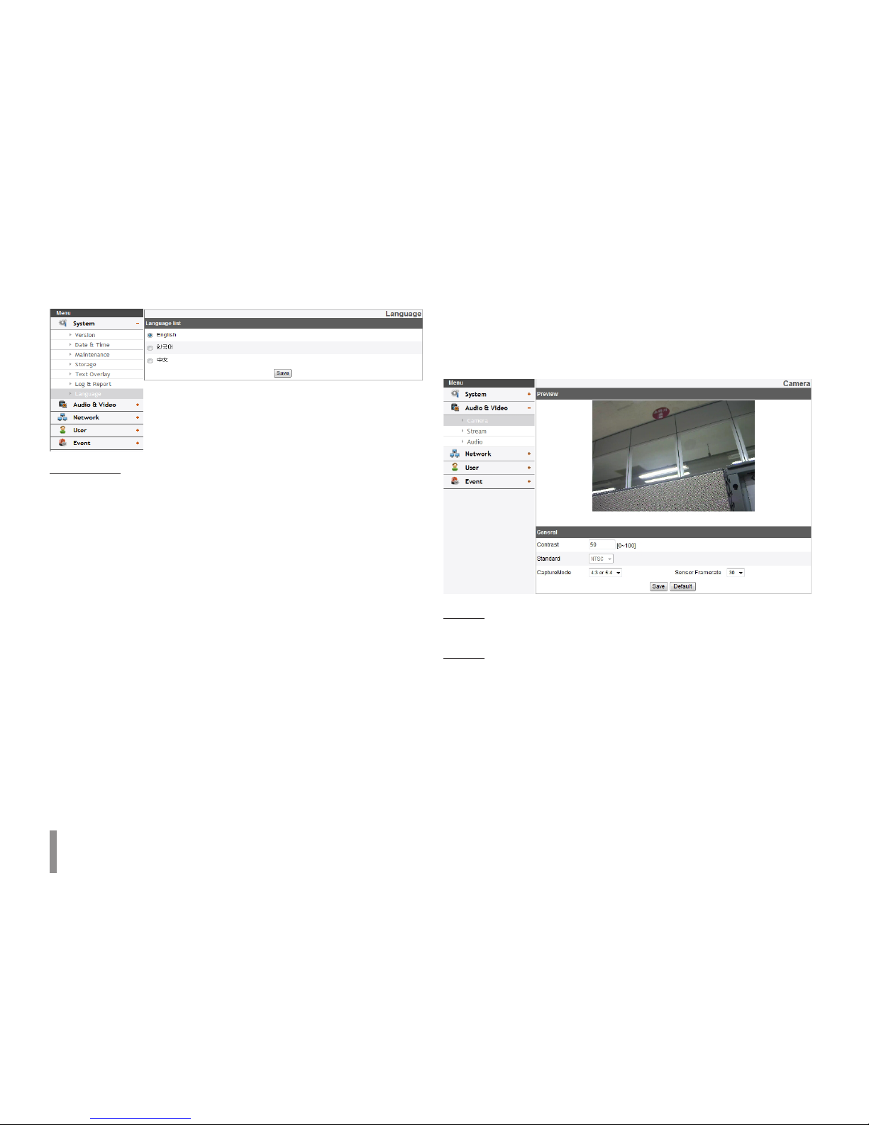
Language
Language list
Select a language for the LG Smart Web Viewer configuration menu
and information display.
• Save: Click this button to confirm the settings.
Audio & Video settings
Camera
Applicable Model: LNB5100 series, LNB3100 series, LND5100
series, LND3100 series, LNV5100 series
Preview
You can preview the camera image on the preview window.
General
> Contrast: Edit the contrast value from 0 to 100. Selecting 100
provides the image with the highest contrast.
> Standard: Displays the video standard of the camera.
> CaptureMode: Select the capture mode.
Note:
If you change the CaptureMode option, the Privacy, WDR/
BLC and HSBLC settings on the OSD menu are initialized.
> Sensor Framerate: You can select the Sensor Framerate value
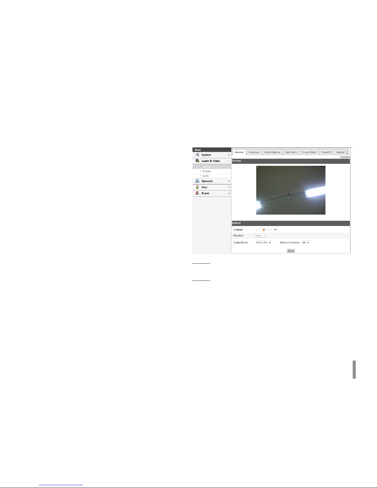
Operation and settings 15
between 30 and 25.
Notes:
• It is recommended to select Sensor Framerate value to
30 in 60 Hz region, 25 in 50 Hz region to reduce flicker.
• Maximum FPS is set 25 when you select Sensor
Framerate value 25.
• Save: Click this button to confirm the settings.
• Default: Click this button to restore the IP device back to original
factory settings.
Note:
The Capture mode and Sensor Framerate are not initialized.
Camera
Applicable Model: LNU5100R series, LNV5100R series,
LND5100R series
Preview
You can preview the camera image on the preview window.
General
> Contrast: Edit the contrast value from 0 to 100. Selecting 100
provides the image with the highest contrast.
> Standard: Displays the video standard of the camera.
> CaptureMode: Select the capture mode.
Note:
If you change the CaptureMode option, the Privacy, WDR/
BLC and HSBLC settings on the OSD menu are initialized.
> Sensor Framerate: You can select the Sensor Framerate value
between 30 and 25.
16 Operation and settings
Notes:
• It is recommended to select Sensor Framerate value to
30 in 60 Hz region, 25 in 50 Hz region to reduce flicker.
• Maximum FPS is set 25 when you select Sensor
Framerate value 25.
• Save: Click this button to confirm the settings.
Exposure
> Mode: Select [Mode] option on the [Exposure] menu, then
select a value.
> WDR/BLC: Use WDR/BLC option to view the object clearly
in backlight conditions. Select [WDR/BLC] option on the
[Exposure] menu.
- WDR: WDR (Wide dynamic range) feature can be very
helpful to cope with very challenging lighting conditions.
It is capable of capturing both of the dark part and
bright part and combining the differences into a scene
to generate a highly realistic image as original scene.
- BLC: Camera’s backlight compensation feature helps
alleviate issues of visibility in high contrast areas.
- HSBLC: Use for masking brightness of the specific area to
view the subject more clearly.
> AREA SETTING: Click the [Show] button to select area.
> GRAY SCALE: Select a gray scale.
> USER SCALE: Set a bright level.
> MASK: Select [ON] or [OFF]. If you set the MASK to
ON, the mask function is activated only when the
HSBLC is activated.
- OFF: Not in use.
> AGC: If the images are too dark, change the maximum [AGC]
value to make the images bright.
> Brightness: You can increase the brightness of the darkened
video. If you set the brightness to lower value, the image
gets darkened. If you set the brightness to higher value, the
image gets bright.
> Shutter Speed: Select the desired shutter speed for camera
exposure. You can change the shutter speed to higher speed
to capture fast-moving subjects, though the image becomes
darker.
- Max Shutter: When the [Shutter Speed] is on AUTO
mode, the [Max Shutter] function is activated. It limits
the maximum value of the [Shutter Speed].
> Sens-Up: If pictures are not clear due to darkness, this Sens-
Operation and settings 17
Up operation would increase the sensitivity of picture.
Note:
If you set to one of the [Shtter Speed] options except AUTO
on the [Shtter Speed] menu or [AGC] to [OFF], the [Sens-Up]
setting is not available.
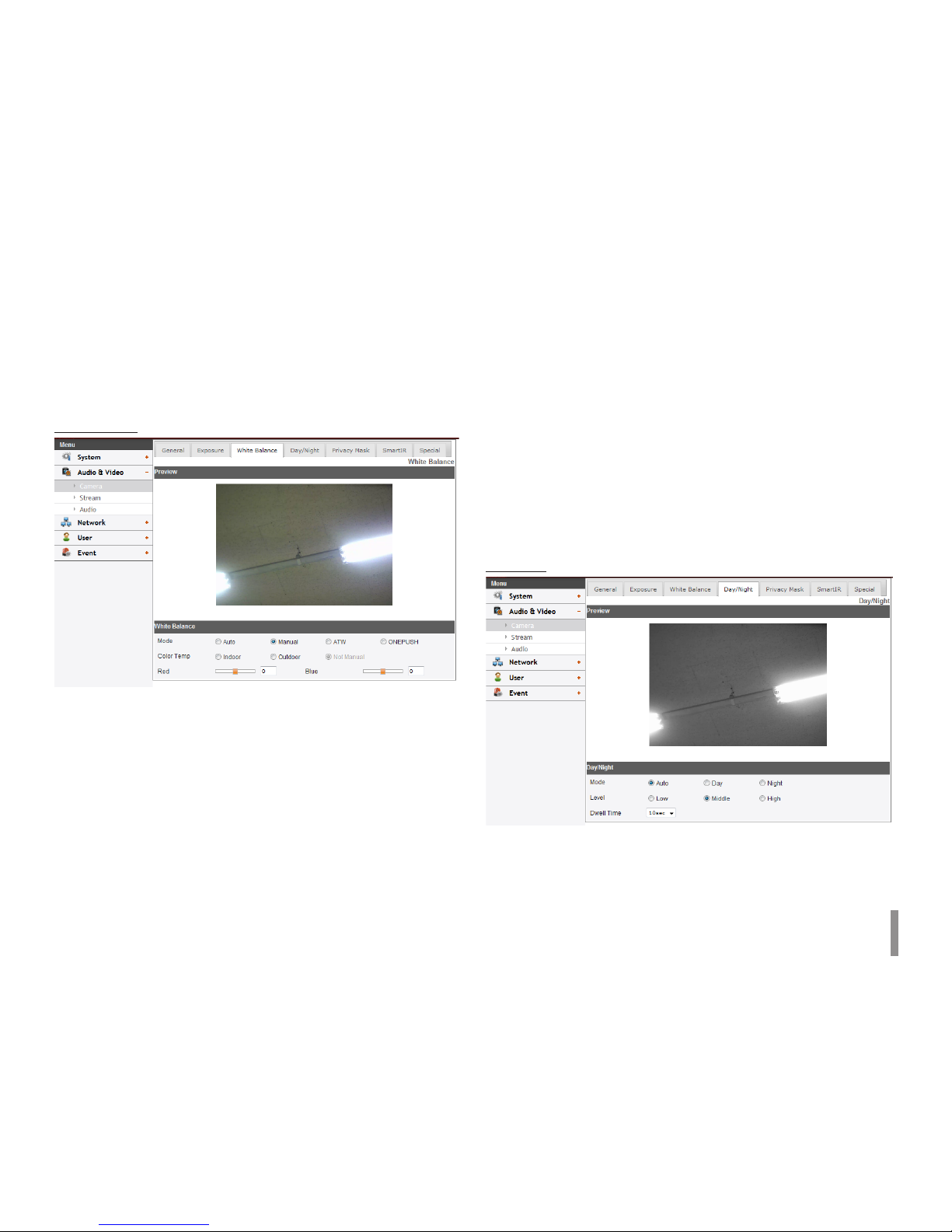
White Balance
> Mode: Select [Mode] option on the [White Balance] menu,
then select the following mode.
- Auto: You can set the white balance options
automatically. When the [Mode] is set to [Auto], [Color
Temp], [Red] and [Blue] option are not activated.
- Manual: You can set the white balance options manually.
> Color Temp: Click to select the option.
- Indoor: The color temperature range for the
proper white balance is approximately 3 200 K.
- Outdoor: The color temperature range for the
proper white balance is approximately 5 100 K.
> Red: Set the desired red value.
> Blue: Set the desired blue value.
- ATW (Auto-Tracing White Balance): In this mode, white
balance has better coverage than auto. Proper white
balance may not be obtained under the following
conditions:
1. When the scene contains mostly high color
temperature objects, such as a blue sky or sunset.
2. When the scene is dim.
- ONE PUSH: If you select the [ONE PUSH] mode, you will
be able to set up the White Balance automatically.
Day/Night
> Mode: Select [Mode] option on the [Day/Night] menu, then
select the following mode.
- Auto: [Day/Night] mode changes automatically.
- Day: Color mode enabled.
18 Operation and settings
- Night: Black-and-white mode enabled.
> Level: Click the option to select a level.
> Dwell Time: Click the drop-down list to select a dwell time.
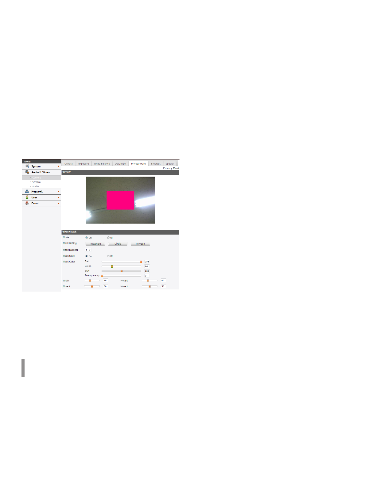
Privacy Mask
This function is aiming at the protection of personal privacy. The
selected part is not displayed on the screen.
> Mode: Select [ON] to set the Mask Setting menu.
> Mask Setting: Select a type of Mask Setting.
Note:
The mask area can be set in different ways, depending on
the type of Mask Setting.
• RECTANGLE :
- Mask Number: Click the drop-down list to select one
of the [Mask Number].
- Mask State: Set to [On] or [Off] on the [Mask State]
menu. When you set to [On], [Mask Color], [Width],
[Height], [Move X] and [Move Y] option is activated.
- Mask Color : You can make any color by adjusting
R.G.B LEVEL and adjust the transparency of MASK.
- Height: Increase or decrease the vertical size of the
mask.
- Width: Increase or decrease the horizontal size of the
mask.
- Move Y: Moves vertical position of the mask.
- Move X: Moves horizontal position of the mask.
• CIRCLE :
- Mask Number: Click the drop-down list to select one
of the [Mask Number].
- Mask State: Set to [On] or [Off] on the [Mask State]
menu. When you set to [On], [Mask Color], [Width],
[Height], [Move X],[Move Y] and [Radius] option is
activated.
- Mask Color : You can make any color by adjusting
R.G.B LEVEL and adjust the transparency of MASK.
- Height: Increase or decrease the vertical size of the
mask.
- Width: Increase or decrease the horizontal size of the
mask.
- Move Y: Moves vertical position of the mask.
- Move X: Moves horizontal position of the mask.
Operation and settings 19
- Radius : You can adjust the Radius size.
• POLYGON :
- Polygon Setting : Select [Draw] and then Use the
, , , buttons to draw the polygon by moving
each vertex. Select [Move] and then , , ,
buttons to move the polygon.
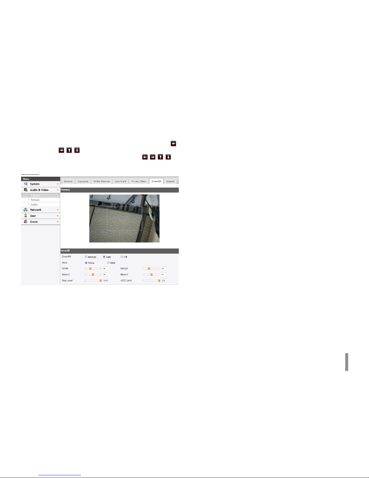
SmartIR
> SmartIR: SmartIR function improve the sensitivity in the
low luminance. SmartIR analyze the image of the screen,
when the subject is close. Then SmartIR reduce the IR LED
brightness and gain to prevent saturation of the closed
subject.
- Manual: When the [Day/Night] menu set to [Night]
mode, user can adjust the brightness of the IR LED.
- Auto: When the [Day/Night] menu set to [Night]
mode, the brightness of the IR LED will be adjusted
automatically.
- OFF: When the [Day/Night] menu set to [Night] mode, IR
LED will be turned off.
> Area: Select the [Show] to display the area setting.
> Width / Height: Adjust the size of the area to the left and
right or up and down.
> Move X / Move Y: Adjust the location of the area to the left
and right or up and down.
> Max Level: Limits the maximum brightness of IR LED. Can be
set from 0 to 200.
> AGC Limit: When the Smart IR is working, limits the value of
maximum gain.
 Loading...