

LG LM-1963C2L INSTALLATION MANUAL
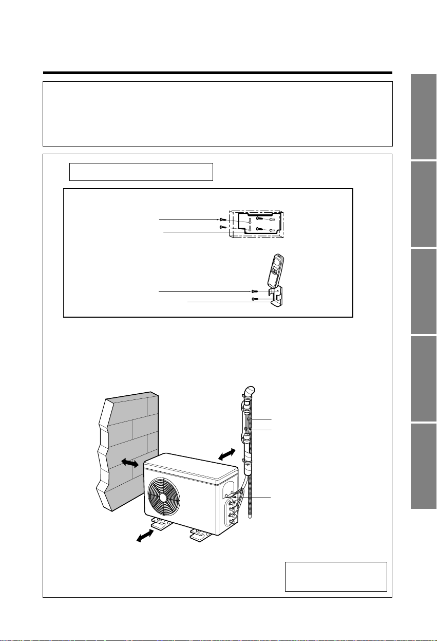
1. Type "A" screw
2. Installation Plate
3. Type "B" screw
4. Holder Remote Control
5. Copper pipe (Liquid side)
6. Copper pipe (Gas side)
7. Connecting cable
more than
10cm
more than
70cm
more than
10cm
more than
10cm
MULTI TYPE ROOM AIR CONDITIONERS
INSTALLATION INSTRUCTIONS
• Please read this instruction sheet completely before installing the product.
• When the power cord is damaged, replacement work shall be performed by authorized personnel
only.
• Installation work must be performed in accordance with the national wiring standards by authorized
personnel only.
P/No. : 3828A20012A
Installation Parts Provided
Cooling & Heating Model
has included Drain Elbow.
ENGLISH ITALIANO ESPAÑOL FRANÇAIS DEUTSCH
2
OUT-LINE OF INSTALLATION
Installation
Requirements
Required Parts Required Tools
The following should be
always observed for safety.3
Installation of indoor, outdoor
unit
............................................
4
❏Level gauge
❏Screw driver
❏Electric drill
❏Hole core drill(ø70mm)
❏ Installation plate
❏Four type "A" screws
❏Connecting cable
Flaring work and connection
of piping
...................................
6
Connection of piping(Indoor)..7
For right rear piping
For left rear piping
Connection of
piping(Outdoor)
..................
10
Connecting the cable
between indoor unit and
outdoor unit
..........................
11
❏Pipes: Gas side
........
1/2", 3/8"
Liquid side
.............
1/4"
(Refer to page 4)
❏Insulation materials
❏Additional drain pipe
(Outer Diameter
.......
15.5mm)
❏Flaring tool set
❏Specified torque wrenches
1.8kg.m, 4.2kg.m, 5.5kg.m,
6.6kg.m
(different depending on model No.)
(Refer to page 10)
❏Spanner..................Half union
Checking the drainage and
Forming the piping
................
13
❏A glass of water
❏Screw driver
Test running
..........................
14 ❏Two type "B" screws ❏Owner's manual
❏Thermometer
❏Holder Remote Control
ENGLISH
3
CAUTION
CAUTION
WARNING
WARNING
CAUTION
CAUTION
WARNING
WARNING
THE FOLLOWING SHOULD BE ALWAYS OBSERVED FOR SAFETY
• Be sure to read "THE FOLLOWING SHOULD ALWAYS BE OBSERVED FOR SAFETY" before installing
the air conditioner.
• Be sure to observe the cautions specified here as they include important items related to safety.
• The indications and meanings are as follows.
• After reading this manual, be sure to keep it together with the instruction manual in a handy place on the
customer's site.
Could lead to death, serious injury, etc.
Could lead to serious injury in particular environments when operated incorrectly.
Do not install it yourself (customer).
• Incomplete installation could cause injury due to
fire, electric shock, the unit falling or a leakage
of water. Consult the dealer from whom you
purchased the unit or special installer.
Perform the drainage/piping work securely
according to the installation manual.
• If there is a defect in the drainage/piping work,
water could drop from the unit and household
goods could be wet and damaged.
Do not install the unit in a place where an
inflammable gas leaks.
• If gas leaks and accumulates in the area
surrounding the unit, it could cause an
explosion.
Perform the installation securely referring to
the installation manual.
• Incomplete installation could cause a personal
injury due to fire, electric shock, the unit falling or
a leakage of water.
Install the unit securely in a place which can
bear the weight of the unit.
• When installed in an insufficient strong place,
the unit could fall causing injured.
Use the specified wires to connect the indoor and outdoor
units securely and attach the wires firmly to the terminal
board connecting sections so the stress of the wires is not
applied to the sections.
• Incomplete connecting and fixing could cause
fire.
Check that the refrigerant gas due not leak
after installation is completed.
Perform electrical work according to the
installation manual and be sure to use an
exclusive circuit.
• If the capacity of the power circuit is insufficient
or there is incomplete electrical work, it could
result in a fire or an electric shock.
Attach the electrical part cover to the indoor
unit and the service panel to the outdoor unit
securely.
• If the electrical part cover if the indoor unit and/or
the service panel if the outdoor unit are not
attached securely, it could result in a fire or
electric shock due to dust, water, etc.
Be sure to use the part provided or specified
parts for the installation work.
• The use of defective parts could cause an injury or leakage
of water due to a fire, electric shock, the unit falling, etc.
4
A
Oil trap
Outdoor unit
Indoor unit
B
Outdoor unit
Indoor unit
A
B
CAUTION
CAUTION
CAUTION
CAUTION
More than 5cm
More than
5cm
More than 2.3m
More than
5cm
more than
10cm
more than
10cm
more than
70cm
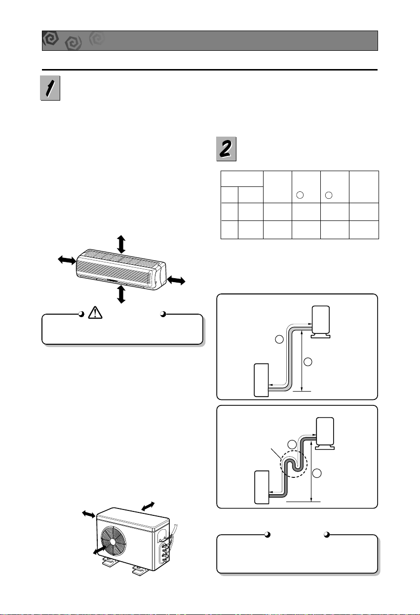
INSTALLATION OF INDOOR, OUTDOOR UNIT
Read completely, then follow step by step.
Select the best location
1. Indoor unit
■ Do not have any heat or steam near the
unit.
■ Select a place where there are no
obstacles in front of the unit.
■ Make sure that condensation drainage can
be conveniently routed away.
■ Do not install near a doorway.
■ Ensure that the space around the left and
right of the unit is more than 5cm. The unit
should be installed as high on the wall as
possible, allowing a minimum of 5cm from
ceiling.
■ Use a stud finder to locate studs to prevent
unnecessary damage to the wall.
■ Rooftop Installations:
If the outdoor unit is installed on a roof
structure, be sure to level the unit. Ensure the
roof structure and anchoring method are
adequate for the unit location. Consult local
codes regarding rooftop mounting.
Piping length and elevation
2. Outdoor unit
■ If an awning is built over the unit to prevent
direct sunlight or rain exposure, make sure
that heat radiation from the condenser is
not restricted.
■ Ensure that the space around the back
and sides is more than 10cm. The front of
the unit should have more than 70cm of
space.
■ Do not place animals and plants in the
path of the warm air.
■ Take the air conditioner weight into
account and select a place where noise
and vibration are minimum.
■ Select a place so that the warm air and
noise from the air conditioner do not
disturb neighbors.
Install the indoor unit on the wall where the
height from the floors more than 2.3 meters.
3/8" 1/4" 4 or 5 7 15 20
1/2" 1/4" 4 or 5 7 15 20
Pipe Size
GAS LIQUID
Max.
length
A (m)
Additional
Refrigerant
(g/m)
Max.
Elevation
B (m)
Standard
Length
(m)
In case more than 5m
• Capacity is based on standard length and maximum
allowance length is on the basis of reliability.
• Oil trap should be installed every 5~7 meters.
ENGLISH
5
5-7mm
(0.2~0.3")
Indoor
WALL
Outdoor
Hole center
Right rear piping
Left rear piping
ø70mm
ø70mm
50mm
20mm
20mm
80mm
A,B
A,B,C
C
D
D
A,B,D
C
A
B,D
C
ø70mm
Left rear piping Right rear piping
Hole Center Installation plate
A,B
A,B,C
C
D
D
A,B,D
C
A
B,D
C
ø70mm
Left rear piping Right rear piping
Left rear piping Right rear piping
Hole Center
Hole Center
Installation plate
ø70mm
"D"
"C"
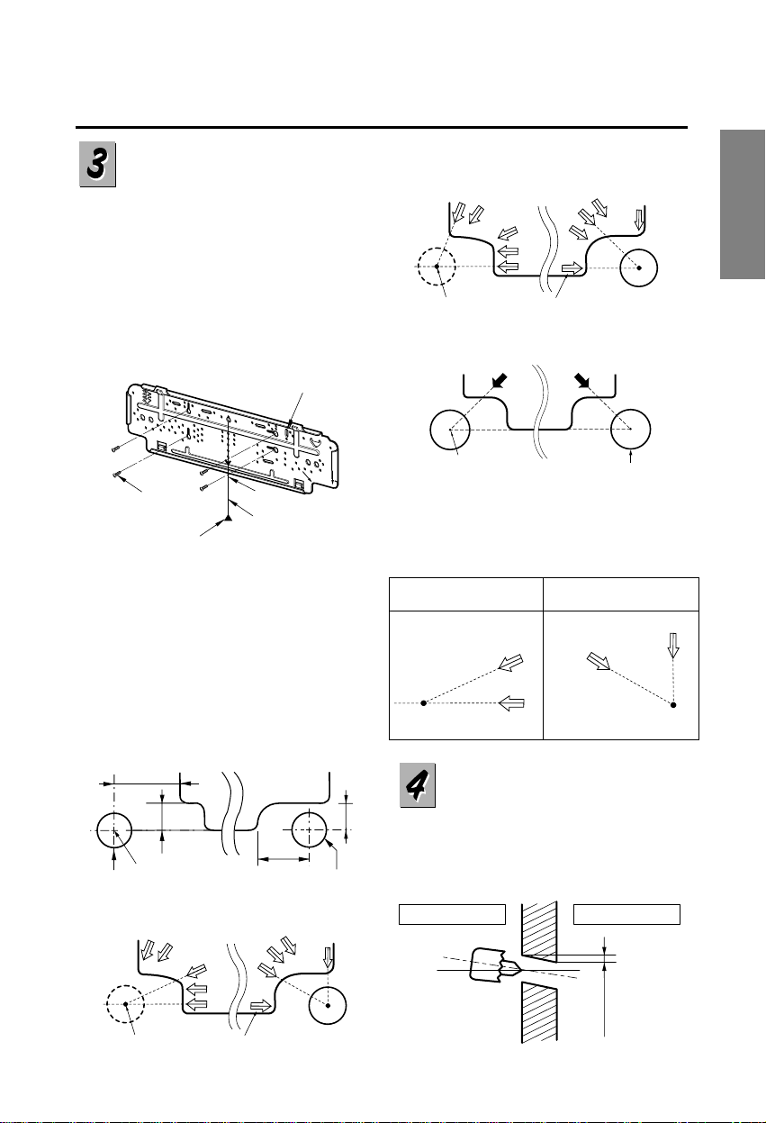
How to fix installation
plate
The wall you select should be strong
and solid enough to prevent vibration
1. Mount the installation plate on the
wall with four type A screws. If
mounting the unit on a concrete wall,
use anchor bolts.
■ Mount the installation plate
horizontally by aligning the centerline
using a level.
2. Measure the wall and mark the
centerline. It is also important to use
caution concerning the location of
the installation plate-routing of the
wiring to power outlets is through the
walls typically. Drilling the hole
through the wall for piping
connections must be done safely.
Drill a hole in the wall
■ Drill the piping hole with a ø70mm
hole core drill. Drill the piping hole at
either the right or the left with the hole
slightly slanted to the outdoor side.
Installation Plate
Marking-off line
Thread
Weight
Type "A" screw
10K, 12K, 14K, 15K Btu
7K, 8K, 9.5K Btu
11K Btu
17.5K Btu
■ For right rear piping and left rear piping, draw a
line in the direction of the arrow marked "A".
The meeting point of the two lines is the center
of the hole.
• The position of the center of the hole.
A
A
A
A
Left holecore position Right holecore position
 Loading...