

LG LH-RH9500P, LHS-95TA9S, LHS-95TA9C, LHS-95TA9A Owner's Manual

Before connecting, operating or adjusting this product,
please read this instruction booklet carefully and completely.
LH-RH9509TA_NA5ILLD_ENG
HDD/DVD
Recorder Receiver System
OWNER’S MANUAL
MODEL:LH-RH9500TA
(Main Unit: LH-RH9500P
Speakers: LHS-95TA9S, LHS-95TA9C,
LHS-95TA9A)
CD-R/RW
2
CAUTION: THESE SERVICING
INSTRUCTIONS ARE FOR USE BY
QUALIFIED SERVICE PERSONNEL ONLY.
TO REDUCE THE RISK OF ELECTRIC
SHOCK DO NOT PERFORM ANY
SERVICING OTHER THAN THAT
CONTAINED IN THE OPERATING
INSTRUCTIONS UNLESS YOU ARE
QUALIFIED TO DO SO.
Caution: The apparatus should not be
exposed to water (dripping or splashing)
and no objects filled with liquids, such as
vases, should be placed on the
apparatus.
CAUTION: This product employs a Laser
System.
To ensure proper use of this product,
please read this owner’s manual carefully
and retain for future reference. Should
the unit require maintenance, contact an
authorized service center.
Use of controls, adjustments, or the
performance of procedures other than
those specified herein may result in
hazardous radiation exposure.
To prevent direct exposure to laser beam,
do not try to open the enclosure. Visible
laser radiation when open. DO NOT
STARE INTO BEAM.
WARNING: Do not install this equipment in
a confined space such as a bookcase or
similar unit.
This product is manufactured to comply with
the radio interference requirements of EEC
DIRECTIVE 89/336/EEC, 93/68/EEC and
73/23/EEC.
CAUTION concerning the Power Cord
Most appliances recommend they be placed upon a
dedicated circuit;
That is, a single outlet circuit which powers only that
appliance and has no additional outlets or branch circuits.
Check the specification page of this owner's manual to be
certain.
Do not overload wall outlets. Overloaded wall outlets,
loose or damaged wall outlets, extension cords, frayed
power cords, or damaged or cracked wire insulation are
dangerous. Any of these conditions could result in electric
shock or fire. Periodically examine the cord of your
appliance, and if its appearance indicates damage or
deterioration, unplug it, discontinue use of the appliance,
and have the cord replaced with an exact replacement
part by an authorized servicer.
Protect the power cord from physical or mechanical
abuse, such as being twisted, kinked, pinched, closed in
a door, or walked upon. Pay particular attention to plugs,
wall outlets, and the point where the cord exits the
appliance.
SERIAL NUMBER:
You can find the serial number on the back of the unit.
This number is unique to this unit and not available to
others. You should record requested information here and
retain this guide as a permanent record of your purchase.
Model No. ______________________________
Serial No. ______________________________
Disposal of your old appliance
1. When this crossed-out wheeled bin symbol
is attached to a product it means the product
is covered by the European Directive
2002/96/EC.
2. All electrical and electronic products should
be disposed of separately from the
municipal waste stream via designated
collection facilities appointed by the
government or the local authorities.
3. The correct disposal of your old appliance
will help prevent potential negative
consequences for the environment and
human health.
4. For more detailed information about disposal
of your old appliance, please contact your
city office, waste disposal service or the
shop where you purchased the product.
CAUTION
RISK OF ELECTRIC SHOCK
DO NOT OPEN
SHOWVIEW is a registered trademarks of Gemstar
Development Corporation.
The S
HOWVIEW System is manufactured under
license from Gemstar Development Corporation.

3
Introduction
Contents
Introduction . . . . . . . . . . . . . . . . . . . . . . . . . . . .4-10
Symbol Used in this Manual . . . . . . . . . . . . . . . .4
Notes on Discs . . . . . . . . . . . . . . . . . . . . . . . . . .4
Recordable and Playable Discs . . . . . . . . . . . . .5
Playable Discs . . . . . . . . . . . . . . . . . . . . . . . . . .6
Remote Control Operation . . . . . . . . . . . . . . . . .6
About the internal hard disk drive . . . . . . . . . . . .7
Card useable on this unit
. . . . . . . . . . . . . . . . . . .7
Disc-related terms . . . . . . . . . . . . . . . . . . . . . . .8
Front Panel . . . . . . . . . . . . . . . . . . . . . . . . . . . . .9
Remote Control . . . . . . . . . . . . . . . . . . . . . . . .10
Hookup and Settings . . . . . . . . . . . . . . . . . . . .11-31
Rear Panel . . . . . . . . . . . . . . . . . . . . . . . . . . . .11
Connecting to the Aerial . . . . . . . . . . . . . . . . . .11
Connections to Your TV . . . . . . . . . . . . . . . . . .12
HDMI Connection . . . . . . . . . . . . . . . . . . . . . . .13
Accessory Audio/Video (A/V) Connections . .14-15
Radio Antenna Connections . . . . . . . . . . . . . . .15
Assembling and Connecting to the Speakers . .16
Speaker System Connections . . . . . . . . . . . . . .17
Speaker Positioning . . . . . . . . . . . . . . . . . . . . .18
Mini Glossary for Sound Mode . . . . . . . . . . . . .19
Delay Time Setting . . . . . . . . . . . . . . . . . . . .20-21
Sound Level . . . . . . . . . . . . . . . . . . . . . . . . . . .21
Test Tone . . . . . . . . . . . . . . . . . . . . . . . . . . . . .21
XTS (Excellent True Sound) . . . . . . . . . . . . . . .21
XTS pro . . . . . . . . . . . . . . . . . . . . . . . . . . . . . .21
Using the Home Menu . . . . . . . . . . . . . . . . . . .22
Initial Settings . . . . . . . . . . . . . . . . . . . . . . . . . .22
General Settings . . . . . . . . . . . . . . . . . . . . .22-25
Auto Programming . . . . . . . . . . . . . . . . . . .22
Program Edit . . . . . . . . . . . . . . . . . . . . . . . .23
AV1 Decoder . . . . . . . . . . . . . . . . . . . . . . . .23
Auto Clock Set . . . . . . . . . . . . . . . . . . . . . .24
Manual Clock Set . . . . . . . . . . . . . . . . . . . .24
TV Aspect . . . . . . . . . . . . . . . . . . . . . . . . . .24
Display Mode . . . . . . . . . . . . . . . . . . . . . . .24
Progressive Scan . . . . . . . . . . . . . . . . . . . .25
PBC . . . . . . . . . . . . . . . . . . . . . . . . . . . . . .25
Initialization . . . . . . . . . . . . . . . . . . . . . . . . .25
Language Settings . . . . . . . . . . . . . . . . . . . .25-26
Audio Settings . . . . . . . . . . . . . . . . . . . . . . . . .26
Dolby Digital . . . . . . . . . . . . . . . . . . . . . . . .26
DRC (Dynamic Range Control) . . . . . . . . . .26
Lock (Parental Control) Settings . . . . . . . . . .27-28
Rating / Set Password / Area Code . . . . . . .27
DivX Registration Code . . . . . . . . . . . . . . .28
Recording Settings . . . . . . . . . . . . . . . . . . .28-29
Record Mode Set . . . . . . . . . . . . . . . . . . . .28
Record Aspect . . . . . . . . . . . . . . . . . . . . . . .28
DV Recording Audio . . . . . . . . . . . . . . . . . .29
TV Recording Audio . . . . . . . . . . . . . . . . . .29
Auto Chapter . . . . . . . . . . . . . . . . . . . . . . . .29
Disc Settings . . . . . . . . . . . . . . . . . . . . . . . .29-31
Disc Format . . . . . . . . . . . . . . . . . . . . . . . .29
Finalize / Disc Label / Disc Protect . . . . . . .30
General Explanation of On-Screen Display . . . .31
Playback . . . . . . . . . . . . . . . . . . . . . . . . . . . . .32-44
Playing a HDD, DVD, DivX file or Video CD .32-35
Playing a DivX Movie File . . . . . . . . . . . . . .36-37
Playing an Audio CD or MP3/WMA file . . . . .38-39
Program Playback with Audio CD and
MP3/WMA file . . . . . . . . . . . . . . . . . . . . . . . . . .40
Viewing a JPEG File . . . . . . . . . . . . . . . . . .41-42
Editing a MP3/WMA, JPEG, DivX file . . . . . .43-44
Recording . . . . . . . . . . . . . . . . . . . . . . . . . . . .45-51
About DVD recording . . . . . . . . . . . . . . . . . . . .45
About HDD recording . . . . . . . . . . . . . . . . . . . .45
Timeshift . . . . . . . . . . . . . . . . . . . . . . . . . . . . . .46
Basic Recording from a TV . . . . . . . . . . . . . . . .47
Instant Timer Recording . . . . . . . . . . . . . . . . . .47
Timer Recording . . . . . . . . . . . . . . . . . . . . . . . .48
Simultaneous recording and playback . . . . . . . .48
Timer Recording with S
HOWVIEW
®
System . . . . .49
Checking Timer Recording Details . . . . . . . . . .50
Recording from an External Input . . . . . . . . . . .50
Recording from DV Input . . . . . . . . . . . . . . . . .51
Editing . . . . . . . . . . . . . . . . . . . . . . . . . . . . . . .52-58
Title List and Chapter List Menu Overview . . . .52
HDD, VR Mode: Original and Playlist Editing . . .53
Adding Chapter Markers . . . . . . . . . . . . . . . . .53
Changing Title Thumbnails . . . . . . . . . . . . . . . .53
Making a New Playlist . . . . . . . . . . . . . . . . . . . .54
Adding Additional Title/Chapters to the Playlist .54
Deleting an Original or Playlist Title/Chapter . . .55
Deleting a Part . . . . . . . . . . . . . . . . . . . . . . . . .55
Naming a Title . . . . . . . . . . . . . . . . . . . . . . . . .56
Sort . . . . . . . . . . . . . . . . . . . . . . . . . . . . . . . . .56
Undoing/Redoing the Last Deletion . . . . . . . . . .56
Combining Two Titles Into One . . . . . . . . . . . . .57
Divide One Titles Into Two . . . . . . . . . . . . . . . .57
Combining Two Chapters Into One . . . . . . . . . .57
Moving a Playlist Chapter . . . . . . . . . . . . . . . . .58
Hide a Chapter/Title . . . . . . . . . . . . . . . . . . . . .58
Protect a Title . . . . . . . . . . . . . . . . . . . . . . . . . .58
Dubbing . . . . . . . . . . . . . . . . . . . . . . . . . . . . . .59-61
Before Dubbing . . . . . . . . . . . . . . . . . . . . . . . . .59
Dubbing from HDD to DVD . . . . . . . . . . . . . . .60
Dubbing from DVD to HDD . . . . . . . . . . . . . . . .60
One Touch Copy (HDD to DVD) . . . . . . . . . . . .61
One Touch Copy (DVD to HDD) . . . . . . . . . . . .61
Reference . . . . . . . . . . . . . . . . . . . . . . . . . . . .62-69
Additional Information . . . . . . . . . . . . . . . . . . . .62
Overwriting Recording . . . . . . . . . . . . . . . . .62
Viewing Title List menu displayed on other
DVD Recorders or Players . . . . . . . . . . . . .62
Playing Your Recordings on Other DVD
Players (Finalizing a Disc) . . . . . . . . . . . . . .62
Language Codes . . . . . . . . . . . . . . . . . . . . . . .63
Area Codes . . . . . . . . . . . . . . . . . . . . . . . . . . .63
Presseting the Radio Stations . . . . . . . . . . . . . .64
Listening to the Radio . . . . . . . . . . . . . . . . . . .64
RDS Operation . . . . . . . . . . . . . . . . . . . . . . . .65
Programme Search (PTY) . . . . . . . . . . . . . . . .65
Troubleshooting . . . . . . . . . . . . . . . . . . . . . .66-67
Specifications . . . . . . . . . . . . . . . . . . . . . . .68-69
4
To ensure proper use of this product, please read this
owner’s manual carefully and retain for future
reference.
This manual provides information on the operation
and maintenance of your recorder. Should the unit
require service, contact an authorized service location.
Symbol Used in this Manual
The lightning flash symbol alerts you to the
presence of dangerous voltage within the
product enclosure that may constitute a risk of
electric shock.
The exclamation point alerts you to the
presence of important operating and
maintenance / servicing instructions.
Indicates hazards likely to cause harm to the
unit itself or other material damage.
Note:
Indicates special notes and operating features.
Tip:
Indicates tips and hints for making the task easier.
A section whose title has one of the following symbols
are applicable only to the disc represented by the
symbol.
Titles recorded on the HDD
DVD-RW with VR recording mode
DVD-RW with Video recording mode
DVD+RW disc
DVD-R disc
DVD+R disc
DVD-Video disc
Video CDs
Audio CDs
DivX files
MP3 files
WMA files
JPEG files
About the Symbol Display
“ ” may appear on your TV display during
operation and indicates that the function explained in
this owner’s manual is not available on that specific
DVD video disc.
Notes on Discs
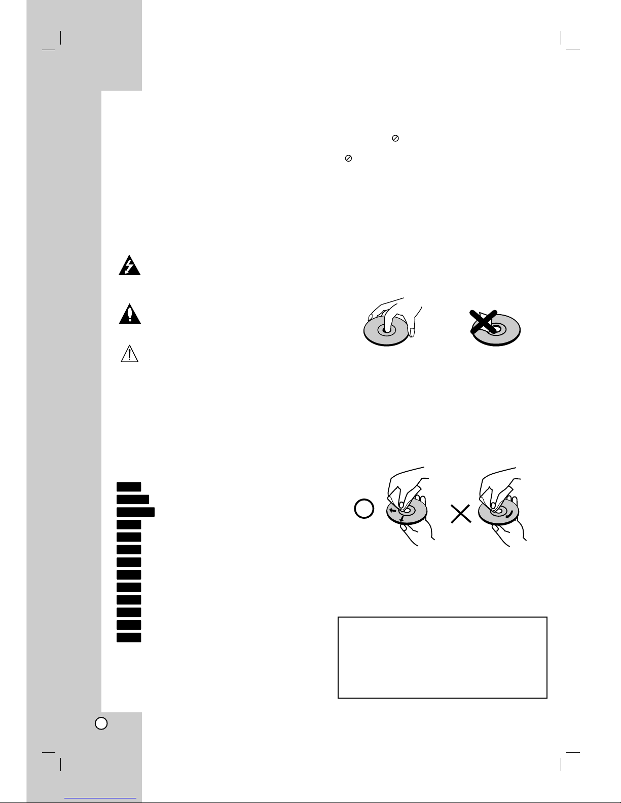
Handling Discs
Do not touch the playback side of the disc. Hold the
disc by the edges so that fingerprints do not get on
the surface. Never stick paper or tape on the disc.
Storing Discs
After playing, store the disc in its case. Do not expose
the disc to direct sunlight or sources of heat and never
leave it in a parked car exposed to direct sunlight.
Cleaning Discs
Fingerprints and dust on the disc can cause poor
picture quality and sound distortion. Before playing,
clean the disc with a clean cloth. Wipe the disc from
the center out.
Do not use strong solvents such as alcohol, benzine,
thinner, commercially available cleaners, or anti-static
spray intended for older vinyl records.
JPEG
WMA
MP3
DivX
ACD
VCD
DVD
+R
-R
+RW
-RW
Video
-RW
VR
HDD
Introduction
Moisture Condensation
Never operate this product immediately after
moving it from a cold location to a warm location.
Leave it for two or three hours without operating it.
If you use this product in such a situation, it may
damage discs/tapes and internal parts.
5
Introduction
Recordable and Playable Discs
DVD-RW (Digital Video Disc - ReWritable):
DVD-RW discs can be formatted for VR mode recording or Video mode recording.
These Discs can be recorded on repeatedly. Recordings can be erased, then you can record again
on the same Disc.
[VR mode]
Recordings can be extensively edited
Playable only on VR mode compatible players (after finalization)
[Video mode]
Playable on regular DVD players (after finalization)
Limited editing features
DVD-R (Digital Video Disc - Recordable)
These Discs can be recorded only once. After you finalize a DVD-R, you cannot record on it or edit it.
DVD-R discs can be only formatted to Video mode.
Playable on regular DVD players (after finalization)
Limited editing features
DVD+RW (Digital Video Disc + ReWritable)
These Discs can be recorded on repeatedly. Recordings can be erased, then you can record again
on the same Disc.
Playable on DVD+RW compatible players (automatically finalization)
The edited contents are playable on DVD+RW compatible players only after finalization
Recordings can be edited the title/chapter
DVD+R (Digital Video Disc + Recordable)
These Discs can be recorded only once. After you finalize a DVD+R, you cannot record on it or edit
it any more.
Playable on DVD+R compatible players (after finalization)
Any edited contents are not be compatible on DVD+R compatible players. (Hide, chapter combine,
added chapter mark, etc.)
Limited title/chapter editing features.
DVD+R DL (Digital Video Disc + Recordable; Double Layer)
These Discs can be recorded only once. After you finalize a DVD+R DL, you cannot record on it or
edit it any more.
Storage space is nearly doubled with double layer DVD+R media, allowing consumers to record up
to 8.5GB of video on a single DVD+R disc.
Playable on DVD+R DL compatible players (after finalization)
Any edited contents are not be compatible on DVD+R DL compatible players. (Hide, chapter
combine, added chapter mark, etc.)
Limited title/chapter editing features.
The recommendable recordable DVD discs
DVD-R DVD+R DVD-RW DVD+RW DVD+R(DL)
SONY (8x, 16x) SONY (2.4x, 4x, 8x, 16x) Victor (1x, 4x) SONY (2.4x) Mitsubishi (2.4x)
TDK (4x, 8x) TDK (4x) Maxell (1x, 2x, 4x) TDK (2.4x) Maxell (2.4x)
Verbatim (4x, 8x) Mitsubishi (4x, 8x) TDK (2x) Philips (4x) -
Panasonic (2x, 4x) Ricoh (2x, 4x, 8x) Mitsubishi (2x) Ricoh (2.4x) -
---HP(2.4x, 4x) -
Note:
If a DVD-RW/DVD+RW discs is recorded using a personal computer or other HDD/DVD Recorder Receiver, you cannot format the disc
using this recorder. So if you want to use the disc on this recorder, you must format the disc using the original recorder.
6
Playable Discs
DVD (8 cm / 12 cm disc)
Discs such as movies that can be purchased or rented
Video CD (VCD) (8 cm / 12 cm disc)
VIDEO CDs or CD-Rs/CD-RWs in VIDEO CD/Super VIDEO CD format
Audio CD (8 cm / 12 cm disc)
Music CDs or CD-Rs/CD-RWs in music CD format that can be purchased
CD-R/CD-RW (8 cm / 12 cm disc)
CD-R/CD-RW discs that contain audio titles, DivX, MP3, WMA, or JPEG files.
Notes:
– Depending on the conditions of the recording equipment or the CD-R/RW (or DVD±R/RW) disc itself, some
CD-R/RW (or DVD±R/RW) discs cannot be played on the unit.
– Do not attach any seal or label to either side (the labeled side or the recorded side) of a disc.
– Do not use irregularly shaped CDs (e.g., heart-shaped or octagonal). Doing so may result in malfunctions.
– Depending on the recording software & the finalization, some recorded discs (CD-R/RW or DVD±R/RW) may
not be playable.
– DVD-R/RW, DVD+R/RW and CD-R/RW discs recorded using a personal computer or a DVD or CD Recorder
may not play if the disc is damaged or dirty, or if there is dirt or condensation on the Recorder’s lens.
– If you record a disc using a personal computer, even if it is recorded in a compatible format, there are cases in
which it may not play because of the settings of the application software used to create the disc. (Check with
the software publisher for more detailed information.)
Regional code of the recorder and DVDs
This recorder is designed and manufactured for playback of Region 2 encoded DVD software. The
region code on the labels of some DVD discs indicates which type of the recorder can play those discs.
This unit can play only DVD discs labeled 2 or ALL. If you try to play any other discs, the message
“Incorrect region code. Can’t play back” will appear on the TV screen. Some DVD discs may not have a region
code label even though their playback is prohibited by area limits.
Notes on DVDs and Video CDs
Some playback operations of DVDs and Video CDs may be intentionally fixed by software manufacturers. As
this unit plays DVDs and Video CDs according to disc content designed by the software manufacturer, some
playback features of the unit may not be available or other functions may be added.
Refer also to the instructions supplied with the DVDs and Video CDs. Some DVDs made for business purposes
may not be played on the unit.
Remote Control Operation
Point the Remote Control at the remote sensor and press the buttons.
Remote Control Battery Installation
Remove the battery cover on the rear of the Remote Control, and insert two R03 (size AAA)
batteries with and matched correctly.
Caution
Do not mix old and new batteries. Never mix different types of batteries (standard, alkaline,
etc.).
2
7
Introduction
About the internal hard disk
drive
The internal hard disk drive (HDD) is a fragile piece of
equipment. Please use the recorder following the
guidelines below to protect against possible HDD
failure.
We recommend that you back up your important
recordings onto DVD discs in order to protect against
accidental loss.
Do not move the recorder while it is on.
Install and use the recorder on a stable, level
surface.
Do not block the rear vent/cooling fan.
Do not use the recorder in excessively hot or humid
places, or in places that may be subject to sudden
changes in temperature. Sudden changes in
temperature can cause condensation to form inside
the recorder. This can be a cause of HDD failure.
While the recorder is switched on, do not unplug
from the wall socket or switch the electricity off from
the breaker switch.
Do not move the recorder immediately after
switching it off. If you need to move the recorder,
please follow the steps below:
1. After the message POWER OFF is shown in the
display, wait at least two minutes.
2. Unplug from the wall socket.
3. Move the recorder.
If there’s a power failure while the recorder is on
there is a chance that some data on the HDD will
be lost.
The HDD is very delicate. If used improperly or in
an unsuitable environment, it is possible that the
HDD will fail after a few years of use. Signs of
problems include playback unexpectedly freezing
and noticeable block noise (mosaic) in the picture.
However, sometimes there will be no warning signs
of HDD failure.
If the HDD fails, no playback of recorded material
will be possible. In this case it will be necessary to
replace the HDD unit.
Card useable on this unit
Compact Flash Card (CF)
Micro Drive (MD)
Secure Digital Card (SD)
Multi Media Card (MMC)
SmartMedia Card (SMC)
xD-Picture Card (xD)
Memory Stick (MS)
Memory Stick Pro (MS-Pro)
Compatible with: FAT 12, FAT 16, or FAT 32
Only use the memory cards recommended above.
Regarding Write Protect
For cards that have a write protect switch, if the switch
is on it will not be possible to write, erase or format
the card.
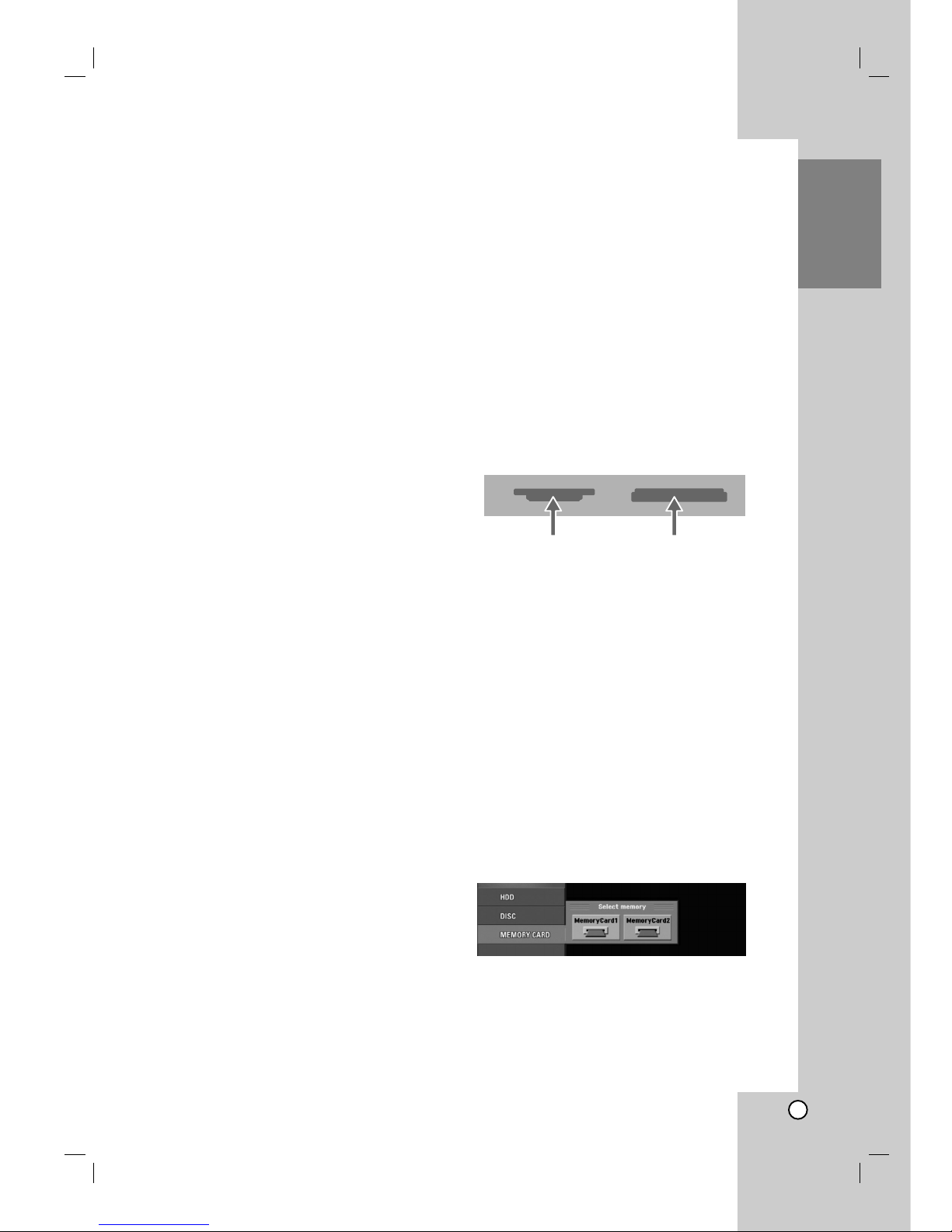
Inserting/Removing the Memory Card
Inserting the card: Insert straight-in until it fits into
place.
Removing the card: Withdraw the card carefully.
Notes:
Keep the memory card out of reach of children. If
swallowed, seek medical advice immediately.
A memory card may not be used for this recorder
Do not extract the memory card in operating
(play, copy, move, etc.).
Using Memory Card
1. Insert a memory card.
2. Press HOME on the remote control.
3. Select [MEMORY CARD] option then press B.
4. Select [Memory Card 1] or [Memory Card 2] then
press ENTER.
5. Select the [TV(HDD)], [MUSIC], or [PHOTO]
option.
Details for the options are on page 22.
Insert CF or MDInsert SD, MMC, SMC,
xD, MS, or MS-Pro card

8
Disc-related terms
DVD +R (Double Layer)
Double layer recording technology offers two
recordable layers on a single DVD disc, providing
nearly double the capacity of 4.7GB single layer
DVDs. The greatest, most valuable benefit of double
layer recording technology is increased capacity.
Storage space is nearly doubled with double layer
DVD+R media, allowing consumers to burn up to
8.5GB of video on a single DVD+R disc.
DVD ±R / DVD ±RW
DVD -R and DVD +R are two different standards for
recordable DVD drives and discs. This format allows
information to be recorded onto the DVD disc only
once. DVD +RW and DVD -RW are two standards for
re-writable media, meaning the DVD content can be
erased and re-recorded. Single-sided discs can hold
4.38 Gigabytes and double-sided discs hold twice as
much.
VCD (Video CD)
A VCD holds up to 74 minutes (650 MB disc) or 80
minutes (700 MB disc) of MPEG-1 full-motion video
along with quality stereo sound.
MPEG
MPEG is an international standard for video and audio
compression. MPEG-1 is used in encoding video for
VCD and provides for multichannel surround sound
coding such as PCM, Dolby Digital, DTS, MP3 and
MPEG audio.
MP3
MP3 is a popular compression format used for digital
audio files that yields very high near-CD quality.
WMA
Windows media audio file. A type of coding / decoding
developed by Microsoft Corp.
JPEG
Joint Pictures Expert Group. JPEG is a compressed
file format that allows you to save images with no limit
on the number of colors.
DivX
DivX is the name of a revolutionary new video codec
which is based on the new MPEG-4 compression
standard for video.You will be able to play DivX
movies using this recorder.
PBC: Playback Control (Video CD only)
Playback control is available for Video CD (VCD)
version 2.0 disc formats. PBC allows you to interact
with the system via menus, search functions, or other
typical computer-like operations. Moreover, still
pictures of high resolution can be played if they are
included in the disc. Video CDs not equipped with
PBC (Version 1.1) operate in the same way as audio
CDs.
Title (DVD video discs only)
A title is generally a distinct section of a DVD disc. For
example the main feature could be title 1, a
documentary describing how the film was made could
be title 2, and cast interviews could be title 3. Each
title is assigned a reference number enabling you to
locate it easily.
Chapter (DVD video discs only)
A chapter is a segment of a title such as a scene in a
film or one interview in a series. Each chapter is
assigned a chapter number, enabling you to locate the
chapter you want. Depending on the disc, chapters
may not be recorded.
Scene (VCD)
On a video CD with PBC (playback control) functions,
moving pictures and still pictures are divided into
sections called “scenes”. Each scene is displayed in
the menu screen and assigned a scene number,
enabling you to locate the scene you want. A scene is
composed of one or several tracks.
Track
A distinct element of audiovisual information, such as
the picture or sound track for a specific language
(DVD), or a musical piece on a video or audio CD.
Each track is assigned a track number, enabling you
to locate the track you want. DVD discs allow one
track of video (with multiple angles) and several tracks
of audio.
9
Introduction
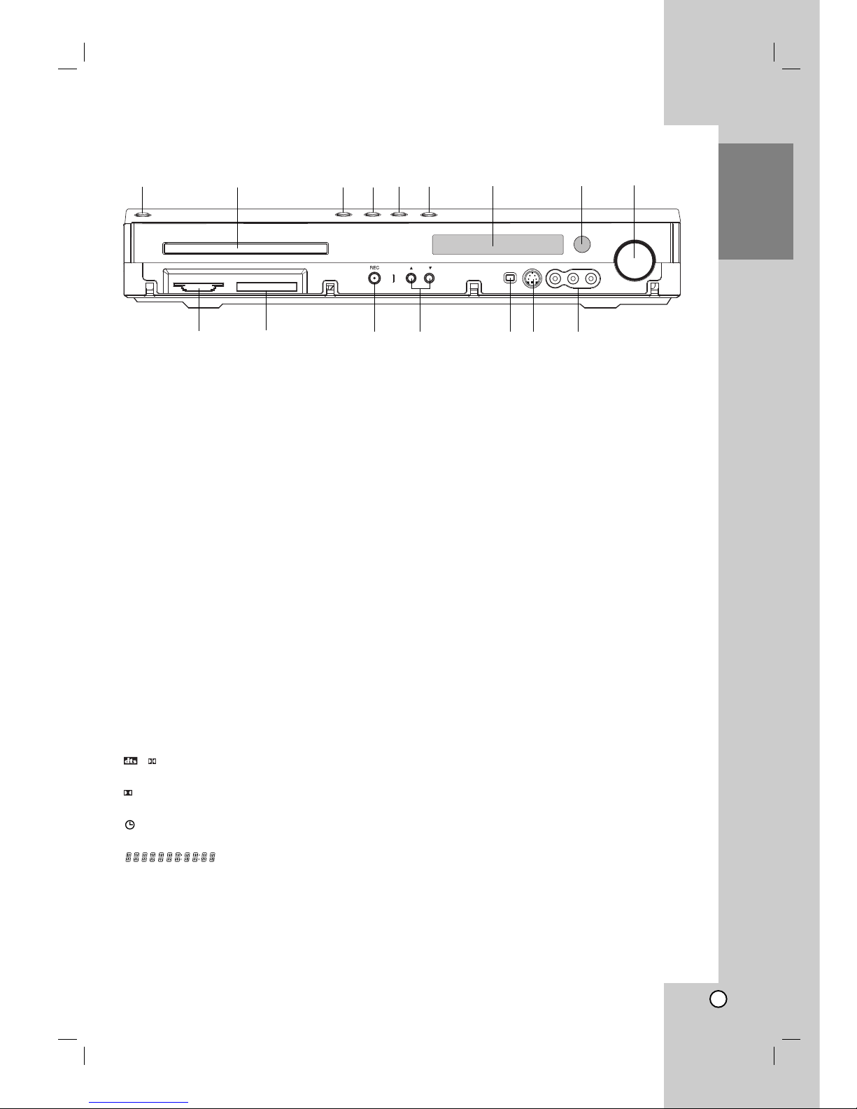
Front Panel
a POWER
Switches the HDD/DVD Recorder Receiver ON or
OFF.
b Disc Tray
Insert a disc here.
c OPEN/CLOSE (Z)
Opens or closes the disc tray.
d B / X (PLAY / PAUSE)
Starts playback.
Pause playback or recording temporarily,
press again to exit pause mode.
e x (STOP)
Stops playback or recording.
f HDD/DVD
Set the recorder’s mode to HDD or DVD.
g Display window
Shows the current status of the recorder.
T/S: Indicates the timeshifting mode.
REC: The recorder is recording.
HDD: The recorder is HDD mode.
DVD: The recorder is DVD mode.
HDD bBDVD: The recorder is dubbing.
MUTE: The speaker sound is muted.
,
: Indicates encoding format of the current
disc.
: Indicates sound mode is DOLBY PRO LOGIC
or DOLBY PRO LOGIC II.
: Indicates when the recorder is in timer recording
or a timer recording is programmed.
: Indicates clock, total playing
time, elapsed time, title number, radio frequency,
volume, Surround, chapter/track number, channel,
etc.
h Remote Sensor
Point the recorder remote control here.
i VOLUME CONTROL
Turn the knob clockwise to increase sound level,
counterclockwise to decrease sound level.
j MEMORY CARD Slot 1
Insert a memory card (SD/MMC/SMC/xD/MS/
MS Pro).
k MEMORY CARD Slot 2
Insert a memory card (CF/MD).
l z (REC)
Starts recording. Press repeatedly to set the
recording time.
m PROG. (v / V)
Scans up or down through memorized channels.
n DV IN
Connect the DV output of a digital camcorder.
o S-VIDEO IN
Connect the S-Video output of an external source
(TV/ Monitor, VCR, Camcorder, etc.).
p AV 2 (VIDEO IN/AUDIO IN (Left/Right))
Connect the audio/video output of an external
source (Audio system, TV/ Monitor, VCR,
Camcorder, etc.).
PLII
D
PROG.
a b
i
j
kl
g
ehf
d
c
m
n o p
10
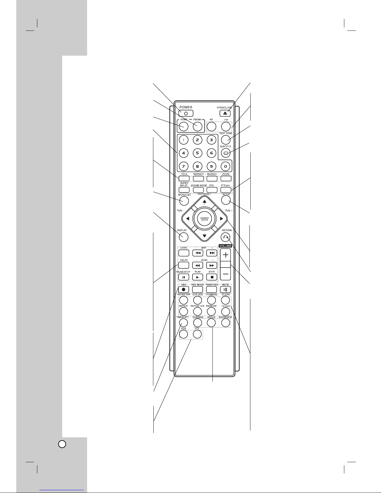
Remote Control
POWER
Turns HDD/DVD Recorder Receiver ON
and OFF.
FM/AM Tuner select
Select FM or AM band as the listening
choice. (FM and AM bands).
HOME
Accesses or removes the HOME menu.
0-9 numerical buttons
Selects numbered options in a menu.
TITLE
Displays the disc’s Title menu, if
available.
MARKER
Marks any point during playback.
SEARCH
Displays Marker Search menu.
ZOOM
Enlarges DVD video image.
MENU/LIST
Accesses menu on a DVD disc,
Switches between Title List-Original and
Title List-Playlist menu.
DISPLAY
Accesses On-Screen Display.
Displays information while viewing a TV
program.
LEVEL
To set the sound level of desired channel.
SKIP(-/+) (. / >)
Go to next chapter or track. Returns to
beginning of current chapter or track or
go to previous chapter or track.
DELAY
To set the delay time of each speaker in
Dolby Digital and Dolby Pro Logic II mode.
SCAN(-/+) (m/M)
Search backward or forward.
PAUSE/STEP (X)
Pause playback or recording
temporarily.
PLAY (B)
Starts playback.
STOP (x)
Stops playback or recording.
z REC
Starts recording. Press repeatedly to set
the recording time.
REC MODE
Selects the recording mode:
HQ, SQ, LQ or EQ.
TIMER REC
Displays Timer Record menu.
MUTE
Turns the sound on and off temporarily.
TIMESHIFT
Activates pause live TV/playback
(timeshift) for a live TV program.
RDS
To view the various displays of the RDS
options.
PTY
To start a search for a specific PTY type.
OPEN/CLOSE
Opens and closes the disc tray.
AV
Changes the input to use for recording.
(Tuner, AV1, AV2, OPT, AV 3, AV4 or DV).
PIP
Selects PIP function on or off.
TEST TONE
To adjust the sound balance of the
speakers from the listener's position.
SUBTITLE
Selects a subtitle language.
AUDIO/MO.ST.
- Selects an audio language.
- Selects STEREO or MONO.
SOUND MODE
Selects sound mode.
XTS
To enjoy great sound effect.
XTS pro
To enjoy more natural and realistic
sound.
SETUP
Accesses or removes the Setup menu.
bBvV(left/right/up/down)
Selects menu options.
PR/PRESET(+/-)(v/V):
Select programme of TV or Radio.
MEMORY/ENTER
- Confirms menu selections.
- Stores a radio station’s frequency in
the tuner’s memory.
RETURN (O)
Removes the menu.
VOLUME (+/-)
To adjust speaker volume and TV
volume.
INSTANT SKIP
Skips 15 seconds forward on the disc
(about the length of a typical TV:
commercial).
CHP ADD
Inserts a chapter marker when playing/
recording.
THUMBNAIL
Selects a thumbnail picture for the
current title for use in the Title List or
Chapter List menu.
CLEAR
Removes a mark on the Marker Search
menu.
REPEAT
Repeat chapter, track, title or all.
REPEAT A-B
Repeats sequence between two points
(A and B)
RANDOM
Plays tracks in random order.
TV/DVD
To view channels selected by the
recorder tuner or by the TV tuner.
DUBBING
Copies DVD to HDD (or HDD to
DVD).
ANGLE
Selects a DVD camera angle, if
available.
SHOWVIEW
To display the program menu for
S
HOWVIEW System programming.
11
Hookup and
Settings
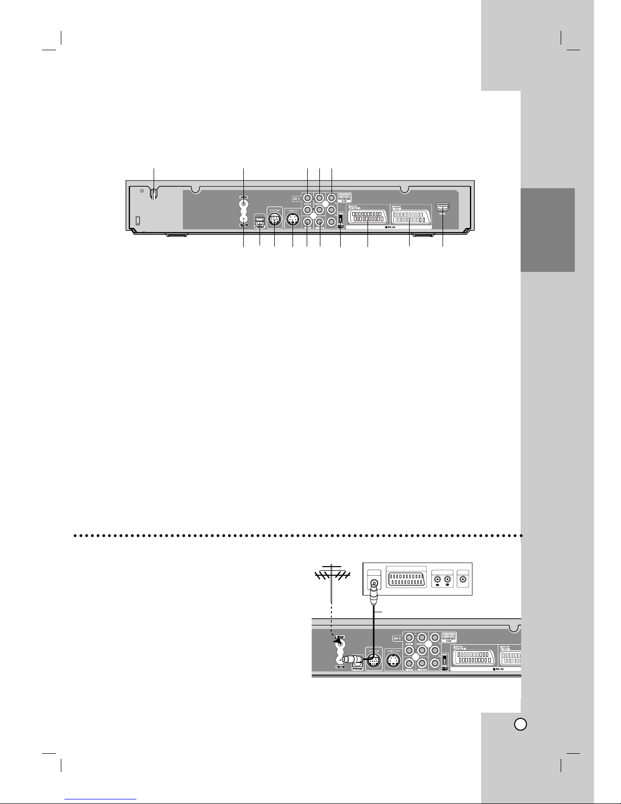
Rear Panel
Hookup and Settings
a AC Power Cord
Plug into the power source.
b ANT.IN
Connect the aerial to this terminal.
c AUDIO IN 1 (Left/Right)
Connect the audio output of an external source
(Audio system, TV/Monitor, VCR, Camcorder).
d AUDIO OUT (Left/Right)
Connect to a TV with audio inputs.
e COMPONENT VIDEO OUT/PROGRESSIVE SCAN
(Pr Pb Y)
Connect to a TV with Pr Pb Y inputs.
f RF. OUT
Passes the signal from the AERIAL to your
TV/monitor
g OPTICAL IN Connector
Connect an optical output of Digital Device.
h SYSTEM
Connect the SPEAKER SYSTEM at the Active
Speaker.
i S-VIDEO OUT (DVD OUT)
Connect to an S-Video Input on TV.
j VIDEO IN 1
Connect the video output of an external source
(Audio system, TV/Monitor, VCR, Camcorder).
k VIDEO OUT
Connect to a TV with video inputs.
l VIDEO OUTPUT Switch
Select either COMPONENT VIDEO OUT/
PROGRESSIVE SCAN or RGB signal of EURO AV1
AUDIO/VIDEO terminal depending on how you
connect the recorder to the TV.
m EURO AV 1 AUDIO/VIDEO
Connect to a TV with SCART jack.
n EURO AV 2 DECODER
Connect the audio/video output of an external
source (Pay-TV decoder, Set Top Box, VCR, etc.).
o HDMI Connector (Type A)
HDMI output providing a high quality interface for
digital audio and video.
Connecting to the Aerial
Remove the aerial cable plug from your TV set and
insert it into the aerial socket at the back of the
recorder. Plug one end of the aerial cable into the TV
socket on the recorder and the other end into the aerial
input socket on your TV set.
RF coaxial connection
Connect the RF. OUT jack on the DVD Recorder
Receiver to the aerial input jack on the TV using the 75ohm Coaxial Cable supplied (R). The RF. OUT jack
passes the signal through from the AERIAL jack.
ANTENNA
INPUT
L
R
AUDIO INPUT
VIDEO
INPUT
SCART INPUT
Aerial
Rear of the HDD/DVD Recorder Receiver
Rear of TV
R
a
i
b
cde
fhg
j
k
n
l m
o
12
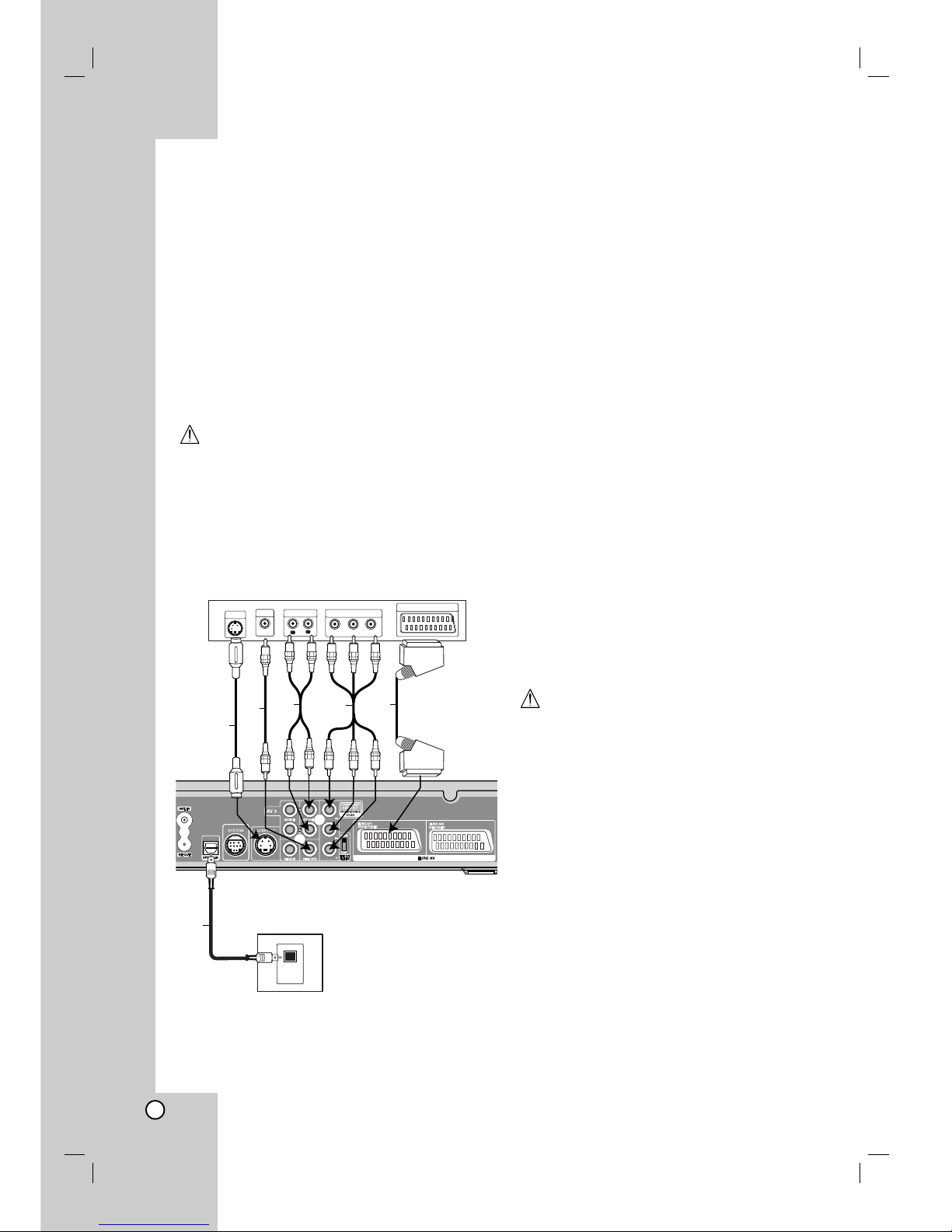
Connections to Your TV
Make one of the following connections, depending
on the capabilities of your existing equipment.
When using the Pr Pb Y jacks, set the VIDEO
OUTPUT switch to COMPONENT. When using the
SCART jack, set the VIDEO OUTPUT switch to
RGB.
Tips
Depending on your TV and other equipment you
wish to connect, there are various ways you could
connect the recorder. Use only one of the
connections described below.
Please refer to the manuals of your TV, VCR,
Stereo System or other devices as necessary to
make the best connections.
Caution
Make sure the recorder is connected directly to the
TV. Tune the TV to the correct video input channel.
Do not connect the recorder’s AUDIO OUT jack to
the phono in jack (record deck) of your audio
system.
Do not connect your recorder via your VCR. The
DVD image could be distorted by the copy
protection system.
S-Video connection
Connect the S-VIDEO OUT jack on the recorder to the
S-Video in jack on the TV using the S-Video cable (S).
Video connection
Connect the VIDEO OUT jack on the recorder to the
video in jack on the TV using the video cable (V).
Audio (Left/Right) Connection
Connect the left and right AUDIO OUT jacks of the
recorder to the audio left and right IN jacks on the TV
using the audio cables (A). Do not connect the
recorder’s AUDIO OUT jack to the phono in jack
(record deck) of your audio system.
Component Video connection
Connect the Pr Pb Y jacks on the recorder to the
corresponding input jacks on the TV using an Y Pb Pr
cable (C).
Progressive Scan connection
If your television is a high-definition or “digital ready”
television, you may take advantage of the recorder’s
progressive scan output for the highest video
resolution possible. If your TV does not accept the
Progressive Scan format, the picture will appear
scrambled if you try Progressive Scan on the recorder.
Connect the Pr Pb Y jacks on the recorder to the
corresponding in jacks on the TV using the Y Pb Pr
cable (C).
Notes:
Set the Progressive to [ON] on the setup menu for
progressive signal, see page 25.
Progressive scan does not work with the analog
video connections (yellow VIDEO OUT jack) or
S-VIDEO connection.
Caution
Once the setting for Progressive Scan output is
entered, an image will only be visible on a
Progressive Scan compatible TV or monitor. If you set
Progressive Scan to ON in error, you must reset the
recorder. First, remove the disc in the recorder. Next,
press STOP (x) and hold it for five seconds before
releasing it. The video output will be restored to the
standard setting, and a picture will once again be
visible on a conventional analog TV or monitor.
SCART connection
Connect the EURO AV1 AUDIO/VIDEO scart jack on
the recorder to the corresponding in jacks on the TV
using the scart cable (T).
Optical Digital Connection
Connect an optical output of DVD Player (or Digital
Device etc) to the OPTICAL IN connector on the
recorder using the optical cable (O).
Note:
When the Optical jack is connected, audio will
output from speakers of the main unit amplifier only
but the audio output is not available via the HDMI
and AV jacks.
L
R
AUDIO INPUT
VIDEO
INPUT
SCART INPUT
Pr
Pb
Y
COMPONENT VIDEO INPUT
Rear of TV
A
V
T
C
Rear of the HDD/DVD Recorder Receiver
S-VIDEO
INPUT
S
DVD Player (or Digital
Device, etc)
OPTICAL
OUT
o
13
Hookup and
Settings
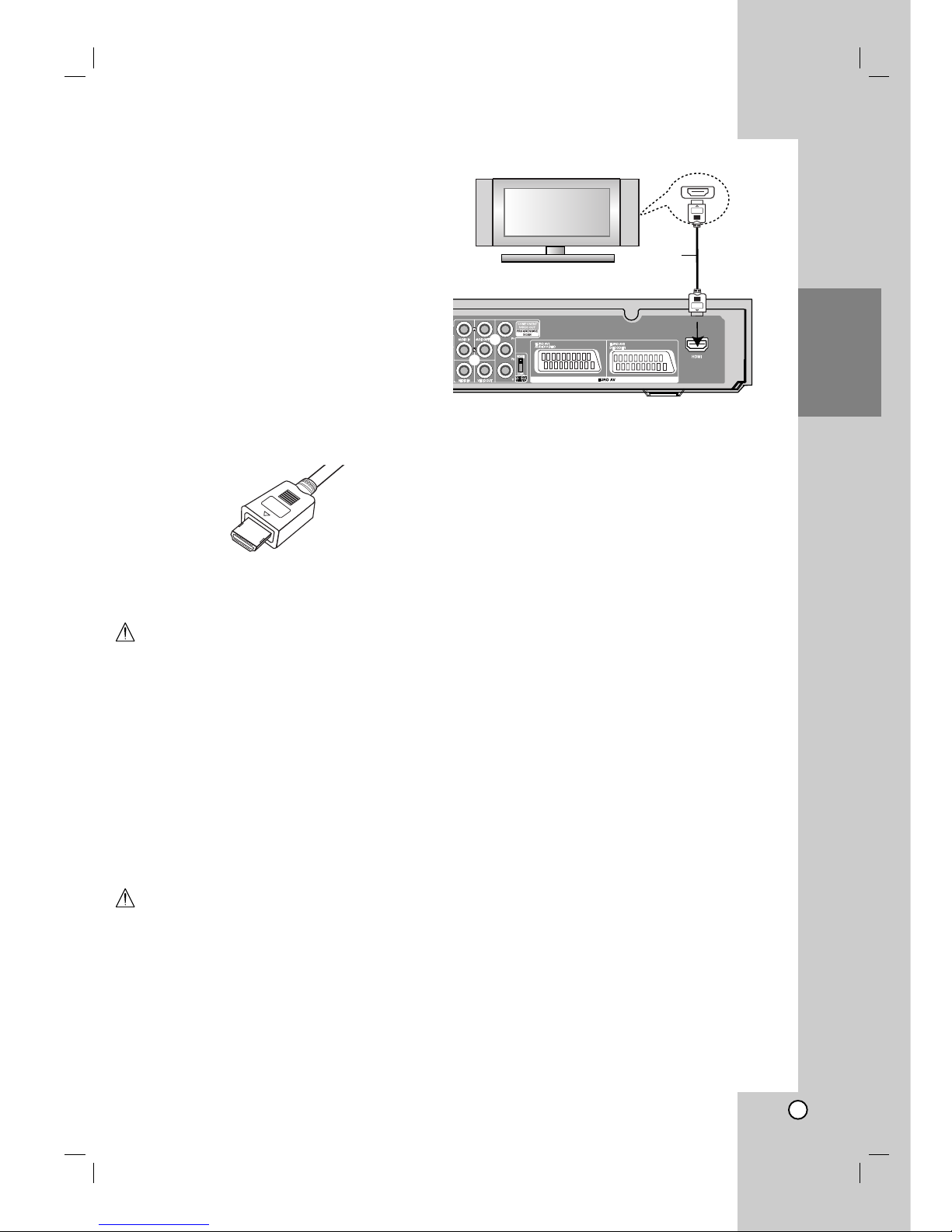
HDMI connection
If you have a HDMI TV or monitor, you can connect it
to this recorder using a HDMI cable.
1. Connect the HDMI jack on the recorder to the
HDMI jack on a HDMI compatible TV or monitor
(H).
2. Set the TV’s source to HDMI (refer to TV’s Owner’s
manual).
Notes:
When you use the HDMI connection, the audio’s
sampling frequency is outputted only with 48KHz
even if you select [96KHz].
The arrow on the cable connector body should face
up for correct alignment with the connector on the
recorder.
If there is noise or lines on the screen, please check
the HDMI cable.
Audio Channel Selection
The Dolby Digital and DTS sound are not available
through the HDMI connection. Set the Dolby Digital to
PCM mode in the setup menu (refer to Audio Settings
on page 26).
Tip :
When you use HDMI connection, you can change the
resolution (576i, 576p) for the HDMI output by setting
the [Progressive Scan] option in the setup menu.
(See page 25)
Progressive Scan ON mode: 576p
Progressive Scan OFF mode: 576i
The recorder does not support 720p and 1080i
resolutions for HDMI.
Caution
Changing the Progressive Scan mode when the
recorder is connected with HDMI connector may result
in malfunctions. To solve the problem, turn off the
recorder and then turn it on again.
About HDMI
HDMI (High Definition Multimedia Interface) supports
both video and audio on a single digital connection for
use with DVD Players, Set-Top Boxes, and other AV
devices.
HDMI was developed to provide the technologies of
HDCP (High Definition Contents Protection). HDCP is
used to protect digital content transmitted and
received.
HDMI, the HDMI logo and High-Definition Multimedia
Interface are trademarks or registered trademarks of
HDMI licensing LLC.
Additional Information for HDMI
When you connect a HDMI or DVI compatible
device make sure of the followings:
-Try switching off the HDMI/DVI device and this
recorder. Next, switch on the HDMI/DVI device
and leave it for around 30 seconds, then switch
on this recorder.
- The connected device’s video input is set
correctly for this unit.
- The connected device is compatible with
720(1440)x576i or 720x576 progressive video
input.
Not all HDCP-compatible DVI devices will work with
this recorder.
- It’s impossible copy protected-DVD title’s
playback in non-HDCP devices.
HDMI
HDMI compatible TV
H
Rear of the HDD/DVD Recorder Receiver
(Type A)
14
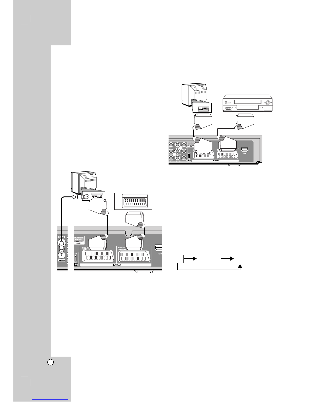
Accessory Audio/Video (A/V)
Connections
Connecting a PAY-TV/Canal Plus Decoder
You can watch or record PAY-TV/Canal Plus
programmes if you connect a decoder (not supplied)
to the recorder. Disconnect the recorder’s mains lead
from the mains when connecting the decoder.
To watch or record PAY-TV/Canal Plus programmes,
set the program’s [Decoder On/Off] option to [On] on
the Setup menu. See “Program Edit” (page 23).
Tip:
You do not need to turn on the recorder to view the
signals from the connected tuner on your TV.
Note:
If you disconnect the recorder’s mains lead, you will
not be able to view the signals from the connected
decoder.
Connecting to the EURO AV2 DECODER
jack
Connect a VCR or similar recording device to the
EURO AV2 DECODER jack of this recorder.
Tip:
You do not need to turn on the recorder to view the
signals from the connected tuner on your TV.
Notes:
Pictures containing copy protection signals that
prohibit any copying cannot be recorded.
If you pass the recorder signals via the VCR, you
may not receive a clear image on your TV screen.
Be sure to connect your VCR to the recorder and
your TV in the order shown below. To watch video
tapes, watch the tapes through a second line input
on your TV.
When you record to a VCR from this recorder, do
not switch the input source to TV by pressing the
TV/DVD button on the remote.
If you are using a B Sky B tuner, be sure to connect
the tuner’s VCR SCART jack to the EURO AV2
DECODER jack.
If you disconnect the recorder’s mains lead, you will
not be able to view the signals from the connected
VCR or tuner.
TV
VCR RECORDER
Line input 1
Line input 2
TV
SCART AV
Rear of the HDD/DVD Recorder Receiver
PAY-TV/Canal Plus
Decorder
Rear of the HDD/DVD Recorder Receiver
VCR, Cable Box, or
Satellite Tuner, etc.
TV
15
Hookup and
Settings
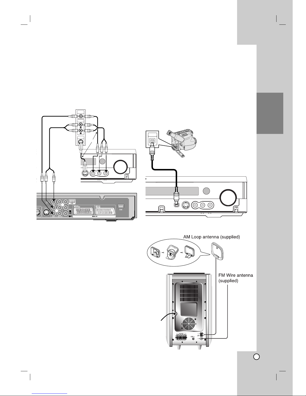
Radio Antenna Connections
Connect the supplied FM/AM antennas for listening to
the radio.
Connect the AM loop antenna to the AM antenna
connector.
Connect the FM wire antenna to the FM antenna
connector.
Notes:
To prevent noise pickup, keep the AM loop antenna
away from the HDD/DVD Recorder Receiver System
and other components.
Be sure to fully extend the FM wire antenna.
After connecting the FM wire antenna, keep it as
close to horizontal as possible.
Connecting to the INPUT 3 or INPUT 4
Jacks
Connect the input jacks (AV3, AV4) on the recorder to
the audio/video out jacks on your accessory
component, using audio/video cables.
Note:
If you use the S-VIDEO IN jack on the front panel, the
VIDEO IN jack on the front panel is not available.
Connecting a Digital Camcorder
Using the front panel DV IN jack, it is possible to
connect a DV digital camcorder and digitally transfer
DV tapes to DVD.
Use a DV cable (not supplied) to connect the DV
in/out jack of your DV camcorder to the front panel DV
IN jack of this recorder.
Note:
This jack is for connection to DV digital camcorder
only. It is not compatible with digital satellite tuners or
D-VHS video decks.
L
R
VIDEO
OUTPUT
AUDIO
OUTPUT
S-VIDEO
OUTPUT
Jack panel of Accessory Component
(VCR, Camcorder, etc.)
Rear of the HDD/DVD Recorder Receiver
Front of the HDD/DVD Recorder Receiver
OR
OR
DV Digital Camcorder
Front of the HDD/DVD Recorder Receiver
DV
IN/OUT
16
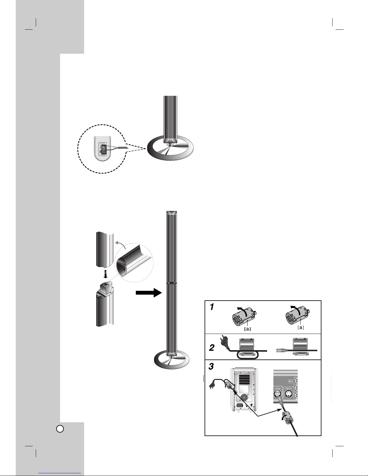
Assembling and Connecting to the Speakers
The speakers are detached from the speaker stands. Connect the speaker cables and assemble the front
speakers from speaker stands as illustrated.
To attach the speaker to the stand
How to connect the Speakers
Connect the speaker cables to the appropriate
terminals on the bottom of each front speaker.
After connecting the speaker cables to the
appropriate terminals on the bottom of each front
speaker and attach the front speakers to the
speaker stands.
Note:
If you hold the top of speakers when carring the front
or rear one, it may cause the seperation of speakers.
Therefore it might be damaged.
About Ferrite Core
Be sure to attach the ferrite core to the System
cable and power cord (for connecting to this unit).
This ferrite core can reduce noises.
How to attach the ferrite core
1. Press the stopper [a] of the ferrite core to open.
2. Insert the System cable to the ferrite core and
wind the power cord once on the ferrite core.
3. Close the ferrite core unit it clicks.
Note:
Attach the ferrite core near the unit (Refer to the
fig.3 and comment.).
The length here is
short as much as
possible.
17
Hookup and
Settings
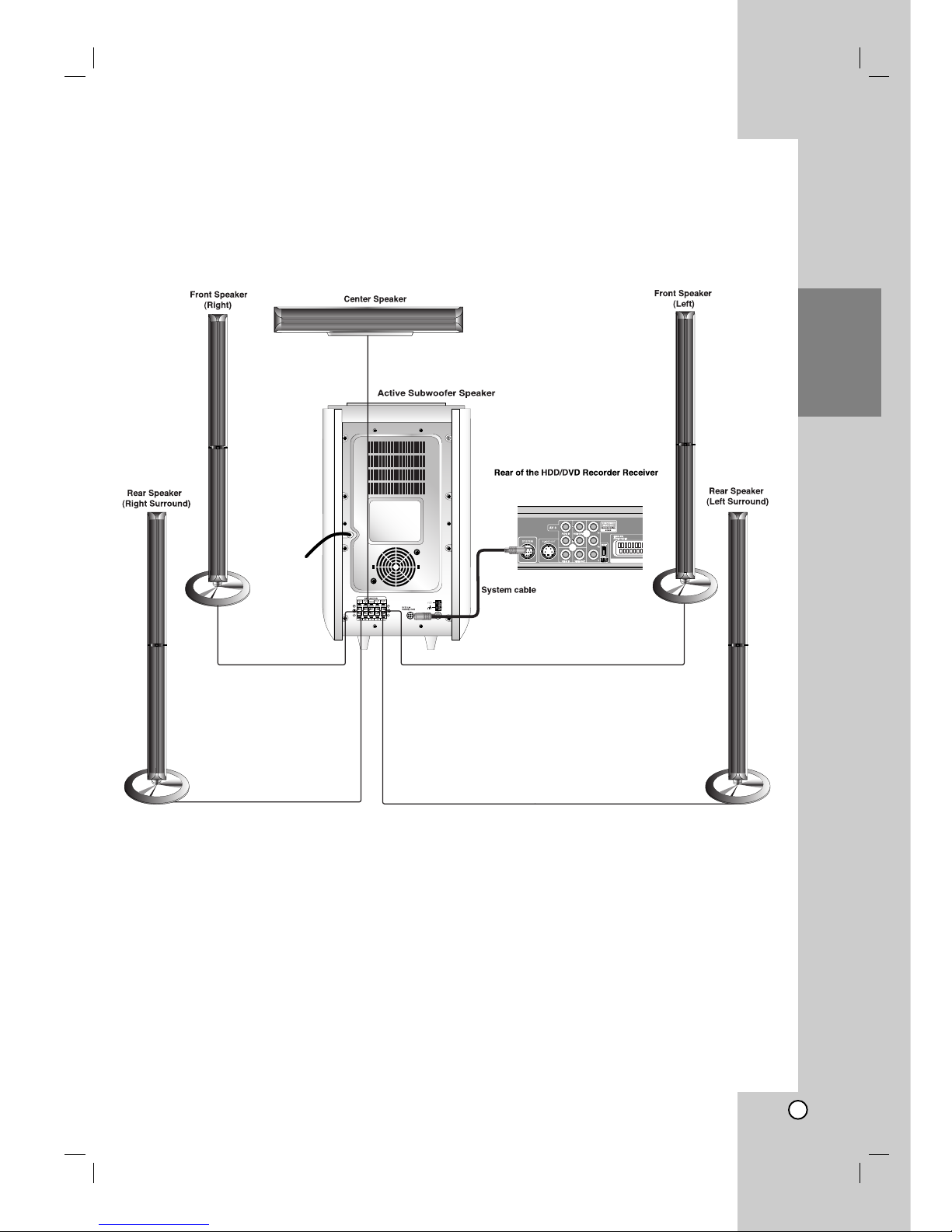
Speaker System Connections
Connect the SYSTEM to the SYSTEM SELECTOR rear of the Active Subwoofer Speaker, using the supplied
System cable.
Connect the speakers using the supplied speaker cables.
To obtain the best possible surround sound, adjust the speaker parameters (volume, distance, etc.).
Notes:
Be sure to match the speaker cable to the appropriate terminal on the components: + to + and – to –. If the cables
are reversed, the sound will be distorted and will lack base.
If you use front speakers with low maximum input rating, adjust the volume carefully to avoid excessive output on
the speakers.
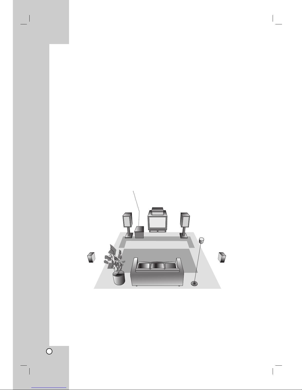
18
Center Speaker
Front Speaker
(Left)
Speaker Positioning Example
Rear Speaker
(Right)
Front Speaker
(Right)
Subwoofer
Speaker Positioning
In the case of normal position use the 6 speakers (2 front speakers, 1 center speaker, 2 rear speakers and
subwoofer).
If you want to play the excellent bass sound, DTS digital surround or Dolby Digital surround, you should connect
a subwoofer.
• Front speakers
According to your listening position set up the speakers for equal distance. And by hearing position set up the
interval between speakers to 45 degree.
• Center speaker
The center speaker and front speakers are ideally the same height. But normally place it above or below the
television.
• Rear speakers
Place left and right behind the listening area. These speakers recreate sound motion and atmosphere required
for surround sound playback. For best results, do not install the rear speakers too far behind the listening
position and install them at or above the level of the listener’s ears. It is also effective to direct the rear
speakers towards a wall or ceiling to further disperse the sound.
In the case of a smaller room size, if the audience is near to the rear wall set the rear speakers opposite each
other, and set the rear speakers above 60 - 90 cm than the listener’s ears.
• Subwoofer
This can be placed in any front position.
Rear Speaker
(Left)

19
Hookup and
Settings
Mini Glossary for Sound Mode
Allows you to enjoy 5.1(or 6) discrete channels of high quality
digital audio from DTS program sources bearing the trademark
such as discs, DVD and compact discs, etc. DTS Digital Surround
delivers up to 6 channels of transparent audio(which means
identical to the original masters) and results in exceptional clarity
throughout a true 360 degree sound field. The term DTS is a
trademark of DTS Technology, LLC. Manufactured under license
from DTS Technology, LLC.
The Dolby Digital surround format lets you enjoy up to 5.1(or 6)
channels of digital surround sound from a Dolby Digital program
source. If you play DVDs with “ ” mark, you can enjoy even
better sound quality, greater spatial accuracy, and improved
dynamic range.
(II)
Dolby Pro Logic II creates five full-bandwidth output channels
from two-channel sources. This is done using an advanced,
high-purity matrix surround decoder that extracts the spatial
properties of the original recording without adding any new
sounds or tonal colorations.
MOVIE mode:
The Movie mode is for use with stereo television shows and all
programs encoded in Dolby Surround. The result is enhanced
soundfield directionality that approaches the quality of discrete
5.1-channel sound.
MUSIC mode:
The Music mode is for use with any stereo music recordings,
and provides a wide and deep sound space. The Music mode
includes controls that allow the sound to be tailored to individual
listening tastes.
MATRIX mode:
The Matrix mode is the same as the Music mode except that the
directional enhancement logic is turned off. It may be used to
enhance mono signals by making them seem “larger.” The
Matrix mode may also find use in auto systems, where the
fluctuations from poor FM stereo reception can otherwise cause
disturbing surround signals from a logic decoder. The ultimate
“cure” for poor FM stereo reception may be simply to force the
audio to mono.
When playing recordings of live music and classic, this mode
provides a feeling similar to actually being in a small concert hall.
When playing recordings of live music and classic, this mode provides
a feeling similar to actually being in a large concert hall.
This mode provides a three dimensional effect similar to that of a
movie theater.
BYPASS (2CH STEREO)
Outputs the sound from the front left and right speakers and
subwoofer.
You can select BYPASS by pressing SOUND MODE on the
remote control.
20
Delay Time Setting
In Dolby Digital or Dolby Pro Logic mode it is
assumed that the distance from the listener to each of
the speakers is equal. If not then setting the delay
times of the center or rear speakers the sound will be
heard simultaneously by the listener.
The interval from the speakers to the listener. If the
distance from the listener to each speaker is the
same, in the Dolby Digital and Dolby Pro Logic mode
the delay time of each speaker is as follows
In Dolby Digital mode
Center delay time : 0 ~ 5ms
Rear delay time: 0 ~ 15ms
In Dolby Pro Logic mode
Center delay time : cannot be set
If the rear delay time is set in Dolby Digital mode, in the
Dolby Pro Logic mode the delay time will be
automatically set.
The delay time is 1 msec per 30 cm.
If the Center and rear speakers are further than the
front speakers from the listener, the delay time will be
at minimum.
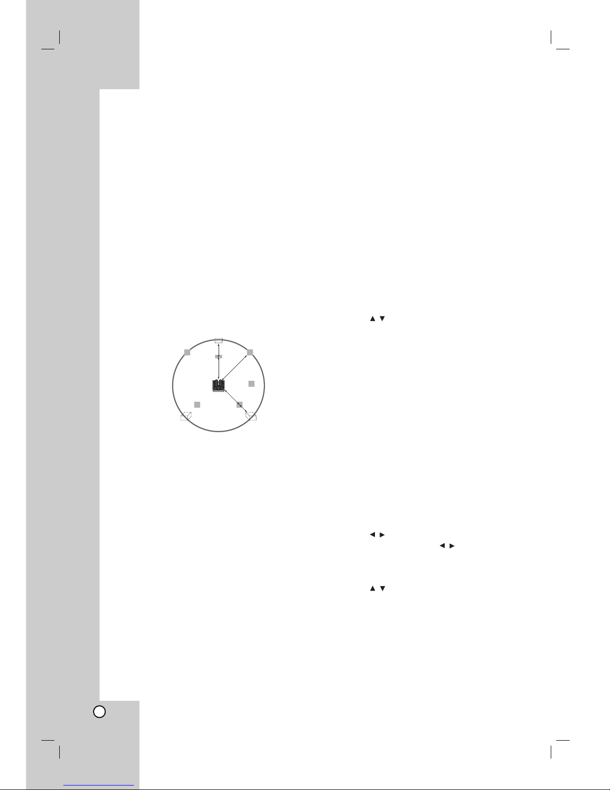
Surround delay time setting
If the distance of DS is equal to or longer than the DF
in the left figure, set the Surround Delay Time as 0ms.
Otherwise, change the setting according to the below.
Ex) If the distance from front speakers to the listener
is 3 m and from rear speakers from the listener is 1.5
m, in the Dolby Digital mode the rear delay time is 5
msec.
3m (D
F) - 1.5m (DS) = 1.5m (B)
1.5m (B) = 150cm / 30cm = 5msec
In Dolby Pro Logic II (Surround delay time):
Pro Logic: 15 ~ 30msec
Movie: 10 ~ 25msec
Music: 0 ~ 15msec
Matrix: 0 ~ 15msec
Center delay time setting (Dolby Digital mode
only)
If the distance of DF is equal to the distance of DC in
the left figure, set the Center Delay Time as 0ms.
Otherwise, change the setting according to the table
below.
Ex) If the distance from the front speakers to the
listener is 3m and from the center speaker to the
listener is 2.4m, the center delay time is 2msec.
3m (DF) - 2.4m (DC) = 60cm (A)
60cm (A) / 30cm = 2msec
Setting the delay time in the Dolby Digital
and Dolby Pro Logic (II) mode
1. Press DELAY.
The current surround delay time appears in the Display
Window.
2. Press /to change the delay time.
3. If setting is complete, press DELAY.
Note:
You can adjust the center delay time only in the
Dolby Digital mode and its delay time appears.
Setting the Sound Effects in the Music
mode of Dolby Pro Logic (II)
1. Press SOUND MODE repeatedly to select the
Music mode.
Each time you press these buttons, the sound
mode is changed in the following order;
PRO LOGIC → PLII MOVIE → PLII MUSIC →
PLII MATRIX→ BYPASS ...
2. Press DELAY.
The current surround delay time appears in the Display
Window.
3. Press /to select a desired Sound mode.
Each time you press the
/
button, it is changed
in the following order;
PANO y C WIDT y DIMEN...
4. Press /to change the steps.
C WIDT: 0 ~ +7
DIMEN: -3 ~ +3
PANO: ON/OFF
5. If setting is complete, press DELAY.
L
SL SR
R
C
D
C
DF
DS
(A)
(B)
SW

21
Hookup and
Settings
PANO (PANORAMA)
This control extends the front stereo image to include
the surround speakers for an exciting “wraparound”
effect with side-wall imaging. It is particularly effective
for recordings which have strong left- or right-channel
elements in the mix, as these are detected and
accentuated by the Panorama process.
C WIDT (Center Width)
This control allows center-channel sounds to be
positioned between the center speaker and the left/right
speakers over a range of eight steps. Step “3” uses a
combination of all three front speakers to give the best
vocal imaging and most seamless soundstage
presentation, and is recommended for most recordings.
Step “0” places all center sound in the center speaker.
Step “7” places all center sound equally in the left/right
speakers, just as in conventional stereo.
DIMEN (DIMENSION)
This control allows the user to gradually adjust the
sound field either towards the front or the rear. This can
be useful to help achieve the desired balance from all
the speakers with certain recordings that may contain
either too much or too little spatial effect. Step “0” is the
recommended setting, which has no effect on the
sound. Steps 1, 2, and 3 gradually move the sound
forward, and steps –1, –2, and –3 move the sound
towards the surrounds.
Sound Level
You can set the sound level of the desired channel.
1. Press LEVEL on the remote control.
The level indicator will appear in the Display Window.
2. Press
/
to select a desired speaker to set.
Each time you press the
/
button, it is changed
in the following order;
FL (Front Left) → C (Center) → FR (Front Right) →
SR (Surround Right) → SL (Surround Left) →
SW (Subwoofer) → FL (Front Left) ...
3. Press
/
to adjust the sound level of the selected
channel. (-6dB ~ +6dB)
4. Repeat step 2-3 and adjust the sound level of the
other channels.
5. If setting is complete, press LEVEL.
Test Tone
This function allows you to can easily adjust the sound
balance of the speakers from the listener's position.
1. Select the test tone mode by pressing TEST TONE.
A hiss noise comes out for 2 seconds from each
speakers in the following order;
FL (Front Left) → C (Center) → FR (Front Right) →
SR (Surround Right) → SL (Surround Left) →
SW (Subwoofer) → FL (Front Left) ...
2. You can adjust the sound level while the test tone is
operating. First press LEVEL then press the
/
buttons, so that the sound level from all the
speakers is same from the listener’s position.
• During the test tone, if you adjust the sound level, it will
be paused in the current speaker channel.
3. If setting is complete, press TEST TONE.
XTS (Excellent True Sound)
You can enjoy the vivid stereophonic sound of the
digital original source without any signal distortion.
Each time you press XTS during 2 channel mode,
the setting changes in the following order.
XTS- 1 → XTS- 2 → XTS- 3 → NORMAL ...
Tips:
XTS- 1: When playing the movie with the weak bass
sound relatively to the general music, it
enforces the sense of sound at woofer
for you to satisfy with.
XTS- 2: In the mode of 2 CH BYPASS, It creates the
high display effect by playing the sound
source via the rear speakers same as the
front speakers.
XTS- 3: You can operate both XTS- 1 and XTS- 2
simultaneously and it can complement the
relative degrading of the sound pitch of the
woofer at the XTS- 2 mode.
Note:
The XTS- 2 mode is temporarily disabled when changing
from 2.1 CH to 5.1 CH and it is enabled when changing it to
2.1 CH.
XTS pro
The unique sound quality of the LG Technology creates
the optimum sound for you to play the perfect playback
of the original sound and to feel the living sound source.
Each time you press XTS pro the setting changes in
the following order.
XTS-PRO ON → XTS-PRO OFF
 Loading...