

LG LHN428HV Installation instructions

INSTALLATION MANUAL
AIR
CONDITIONER
ENGLISH
FRANÇAIS
ESPAÑOL
Please read this installation manual completely before installing the product.
Installation work must be performed in accordance with the national wiring
standards by authorized personnel only.
Please retain this installation manual for future reference after reading it
thoroughly.
Ceilling Concealed Duct
www.lghvac.com
MFL67206507
Rev.04_061220
Copyright © 2013 - 2020 LG Electronics Inc. All Rights Reserved.
www.lg.com

TIPS FOR SAVING ENERGY
2
ENGLISH
TIPS FOR SAVING ENERGY
Here are some tips that will help you minimize the power consumption when you use the air
conditioner. You can use your air conditioner more efficiently by referring to the instructions
below:
• Do not cool excessively indoors. This may be harmful for your health and may consume more
electricity.
• Block sunlight with blinds or curtains while you are operating the air conditioner.
• Keep doors or windows closed tightly while you are operating the air conditioner.
• Adjust the direction of the air flow vertically or horizontally to circulate indoor air.
• Speed up the fan to cool or warm indoor air quickly, in a short period of time.
• Open windows regularly for ventilation as the indoor air quality may deteriorate if the air
conditioner is used for many hours.
• Clean the air filter once every 2 weeks. Dust and impurities collected in the air filter may block the
air flow or weaken the cooling / dehumidifying functions.
For your records
Staple your receipt to this page in case you need it to prove the date of purchase or for warranty
purposes. Write the model number and the serial number here:
Model number :
Serial number :
You can find them on a label on the side of each unit.
Dealer’s name :
Date of purchase :
SAFETY INSTRUCTIONS
3
ENGLISH
SAFETY INSTRUCTIONS
The following safety guidelines are intended to prevent unforeseen risks or damage from unsafe
or incorrect operation of the appliance.
The guidelines are separated into ‘WARNING’ and ‘CAUTION’ as described below.
This symbol is displayed to indicate matters and operations that can cause risk.
!
Read the part with this symbol carefully and follow the instructions in order to avoid risk.
WARNING
!
This indicates that the failure to follow the instructions can cause serious injury or death.
CAUTION
!
This indicates that the failure to follow the instructions can cause the minor injury or damage to
the product.
WARNING
!
• Installation or repairs made by unqualified persons can result in hazards to you and others.
• Installation of all field wiring and components MUST conform with local building codes or, in the absence
of local codes, with the National Electrical Code 70 and the National Building Construction and Safety
Code or Canadian Electrical code and National Building Code of Canada.
• The information contained in the manual is intended for use by a qualified service technician familiar with
safety procedures and equipped with the proper tools and test instruments.
• Failure to carefully read and follow all instructions in this manual can result in equipment malfunction,
property damage, personal injury and/or death.
Installation
• Always perform grounding. - Otherwise, it may cause electrical shock.
• For installation of the product, always contact the service center or a professional installation agency. Otherwise, it may cause a fire, electrical shock, explosion or injury.
• Securely attach the electrical part cover to the indoor unit and the service panel to the outdoor unit.
- If the electrical part cover of the indoor unit and the service panel of the outdoor unit are not attached securely,
it could result in a fire or electric shock due to dust, water, etc.
• Always install an air leakage breaker and a dedicated switching board. - No installation may cause a fire and
electrical shock.
• Do not keep or use flammable gases or combustibles near the air conditioner. - Otherwise, it may cause a fire or
the failure of product.
• Ensure that an installation frame of the outdoor unit is not damaged due to use for a long time.
- It may cause injury or an accident.
• Do not disassemble or repair the product randomly. - It will cause a fire or electrical shock.
• Do not install the product at a place that there is concern of falling down. - Otherwise, it may result in personal
injury.
• Use caution when unpacking and installing. - Sharp edges may cause injury.
• Use a vacuum pump or Inert (nitrogen) gas when doing leakage test or air purge. Do not compress air or Oxygen
and Do not use Flammable gases. Otherwise, it may cause fire or explosion. There is the risk of death, injury, fire
or explosion.

SAFETY INSTRUCTIONS
4
ENGLISH
• Consult your lacal dealer regarding what to do in case of refrigerant leakage.
When the air conditioner is to be installed in a small room, it is necessary to take proper measures so that the
amount of any leaked refrigerant does not exceed the concentration limit in the event of a leakage. Otherwise,
this may lead to an accident due to oxygen depletion.
• Carry out the specified installation work after taking into account earthquakes.
Failure to do so during installation work may result in the unit falling and causing accidents.
• Make sure that a separate power supply circuit is provided for this unit and that all electrical work is carried out by
qualified personnel according to local laws and regulations and this installation manual.
An insufficient power supply capacity or improper electrical construction may lead to electric shocks or fire.
• Be sure to switch off the unit before touching any electrical parts.
• Make sure that all wiring is secured, the specified wires are used, and that there is no strain on the terminal
connections or wires.
• If refrigerant gas leaks during installation, ventilate the area immediately.
Toxic gas may be produced if the refrigerant gas comes into contact with fire.
• Make sure to be materials in a compartment handling air for circulation through a duct supplying only one room.
Operation
• Unplug the unit if strange sounds, smell, or smoke comes from it. - Otherwise, it may cause electrical shock or a
fire.
• Keep the flames away. - Otherwise, it may cause a fire.
• Take the power plug out if necessary, holding the head of the plug and do not touch it with wet hands. -
Otherwise, it may cause a fire or electrical shock.
• Do not open the suction inlet of the indoor/outdoor unit during operation. - Otherwise, it may electrical shock and
failure.
• Do not allow water to run into electrical parts. - Otherwise, it may cause the failure of machine or electrical shock.
• Never touch the metal parts of the unit when removing the filter. - They are sharp and may cause injury.
• Do not step on the indoor/outdoor unit and do not put anything on it. - It may cause an injury through dropping of
the unit or falling down.
• When the product is submerged into water, always contact the service center. - Otherwise, it may cause a fire or
electrical shock.
• Take care so that children may not step on the outdoor unit. - Otherwise, children may be seriously injured due to
falling down.
CAUTION
!
Installation
• Install the drain hose to ensure that drain can be securely done. - Otherwise, it may cause water leakage.
• Install the product so that the noise or hot wind from the outdoor unit may not cause any damage to the
neighbors. - Otherwise, it may cause dispute with the neighbors.
• Always inspect gas leakage after the installation and repair of product. - Otherwise, it may cause the failure of
product.
• Keep level parallel in installing the product. - Otherwise, it may cause vibration or water leakage.
• Do not install the unit in potentially explosive atmospheres.
Operation
• Avoid excessive cooling and perform ventilation sometimes. - Otherwise, it may do harm to your health.
• Use a soft cloth to clean. Do not use wax, thinner, or a strong detergent. - The appearance of the air conditioner
may deteriorate, change color, or develop surface flaws.
• Do not use an appliance for special purposes such as preserving animals vegetables, precision machine, or art
articles. - Otherwise, it may damage your properties.
• Do not place obstacles around the flow inlet or outlet. - Otherwise, it may cause the failure of appliance or an
accident.

TABLE OF CONTENTS
2 TIPS FOR SAVING ENERGY
3 SAFETY INSTRUCTIONS
6 INSTALLATION PARTS
7 INSTALLATION
8 Ceiling dimension and hanging bolt location
9 Indoor Unit Installation
11 Air Filter
12 Checking the Drainage
13 Indoor Unit Drain Piping
14 Combination indoor units
15 Flaring work
16 Connection of piping - Indoor, Outdoor, BD Unit
17 Plumbing materials and storage methods
19 Heat insulation
19 Wiring Connection
19 Connection method of the connecting cable(Example)
22 REMOTE CONTROLLER INSTALLATION
24 Wired remote controller installation
TABLE OF CONTENTS
5
ENGLISH
25 HOW TO SET E.S.P?
25 Installer Setting - E.S.P.
27 SELF-DIAGNOSIS FUNCTION
27 DIP SWITCH SETTING
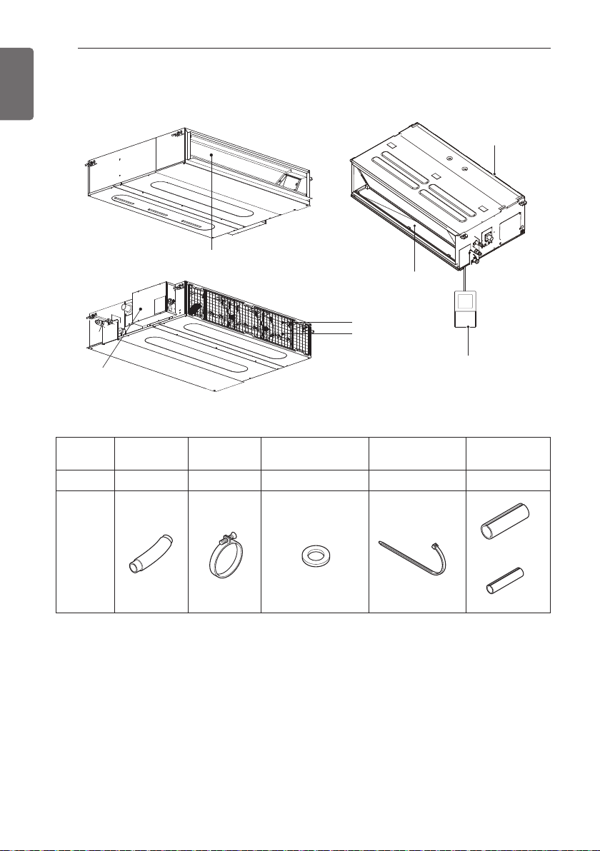
INSTALLATION PARTS
Air outlet vents
Air filters
Control box
Air intake vents
Remote Controller
Air inlet vents
Air outlet vents
(Accessory)
6
ENGLISH
INSTALLATION PARTS
Name Drain hose Clamp metal
Quantity 1 EA 2 EA 8 EA 4 EA 1 set
Shape
* Screws for fixing panels are attached to decoration panel.
Washer for
hanging bracket
Clamp
(Tie Wrap)
Insulation for
fitting
for gas pipe
for liquid pipe
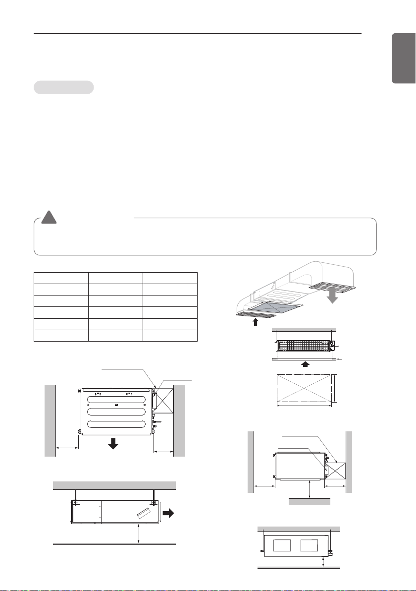
INSTALLATION
A(Min)
Ceiling
Service Space
A
B
B(Min)
H=20 (25/32)
or more
• Suitable dimension "H" is necessary to
get a slope to drain as shown in the figure
Side view [Unit: mm(inch)]
Air outlet
Inspection hole
600 x 600
(23-5/8 x 23-5/8)
Control box
600
(23-5/8)
600
(23-5/8)
Top view [Unit: mm(inch)]
Air outlet
INSTALLATION
Indoor unit
Install the air conditioner in the location that satisfies the following conditions.
- The place shall easily bear a load exceeding four times the indoor unit’s weight.
- The place shall be able to inspect the unit as the figure.
- The place where the unit shall be leveled.
- The place shall easily connect with the outdoor unit.
- The place where the unit is not affected by an electrical noise.
- The place where air circulation in the room will be good .
- There should not be any heat source or steam near the unit
Confirm the positional relationship between the unit and suspension bolts.
- Installation the ceiling opening to clean the filter or service under the product.
WARNING
!
Make sure to be materials in a compartment handling air for circulation through a duct
supplying only one room.
[Unit:mm(inch)]
Capacity (kBtu/h)
9
12/18
24
36
42/48
A B
800 (31-1/2) 800 (31-1/2)
800 (31-1/2) 1 000 (39-3/8)
800 (31-1/2) 1000 (39-3/8)
800 (31-1/2) 1400 (55-1/8)
800 (31-1/2) 1400 (55-1/8)
7
ENGLISH
Top view
Inspection hole
600(23-5/8) X 600(23-5/8)
Control box
600(23-5/8) 600(23-5/8)
Front view
(unit: mm(inch))
1 000
(39-3/8)
Front
20(25/32) or more
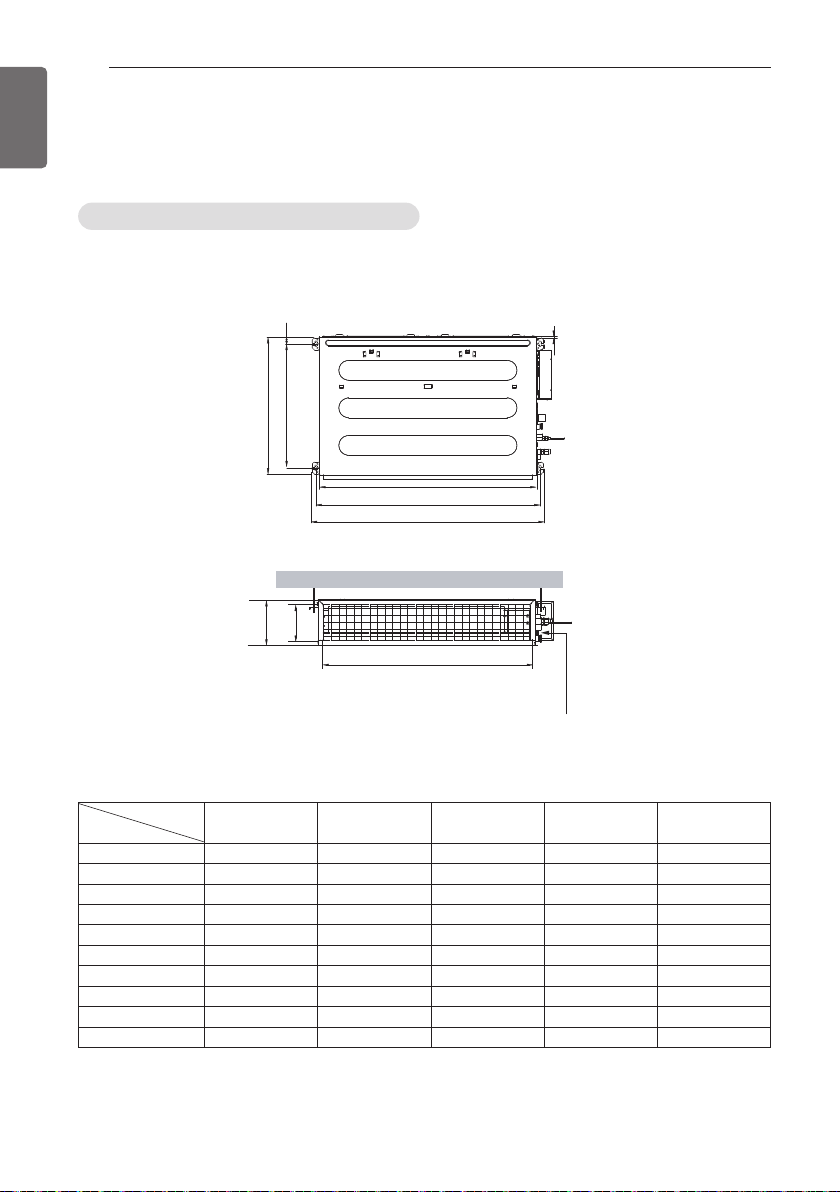
INSTALLATION
C
E
G
D
F
I
A
J
B
H
Drainage hole
8
ENGLISH
Ceiling dimension and hanging bolt location
Installation of Unit
Install the unit above the ceiling correctly.
POSITION OF SUSPENSION BOLT
- Apply a joint-canvas between the unit and duct to absorb unnecessary vibration.
- Apply a filter Accessory at air return hole.
Capacity (kBtu/h)
Dimension
A
B
C
D
E
F
G
H
I
J
9 k 12 k / 18 k 24 k 36 k 42 k / 48 k
733 (28-17/20) 933 (36-37/50) 933.4 (36-3/4) 1 283.4 (50-17/32) 1 283.4 (50-17/32)
772 (30-2/5) 972 (38-13/50) 971.6 (38-1/4) 1 321.6 (52-1/32) 1 321.6 (52-1/32)
628 (24-18/25) 628 (24-18/25) 619.2 (24-3/8) 619.2 (24-3/8) 619.2 (24-3/8)
700 (27-11/20) 700 (27-11/20) 700 (27-9/16) 700 (27-9/16) 700 (27-9/16)
36 (1-2/5) 36 (1-2/5) 30 (1-3/16) 30 (1-3/16) 30 (1-3/16)
190 (7-12/25) 190 (7-12/25) 270 (10-5/8) 270 (10-5/8) 360 (14-3/16)
20 (25/32) 20 (25/32) 15.2 (19/32) 15.2 (19/32) 15.2 (19/32)
660 (25-49/50) 860 (33-17/20) 858 (33-25/32) 1 208 (47-9/16) 1 208 (47-9/16)
155 (6-1/10) 155 (6-1/10) 201.4 (7-15/16) 201.4 (7-15/16) 291.4 (11-15/32)
700 (27-11/20) 900 (35-11/25) 900 (35-7/16) 1 250 (49-7/32) 1 250 (49-7/32)
[Unit:mm(inch)]
h Install the unit leaning to a drainage hole side as a figure for easy water drainage.
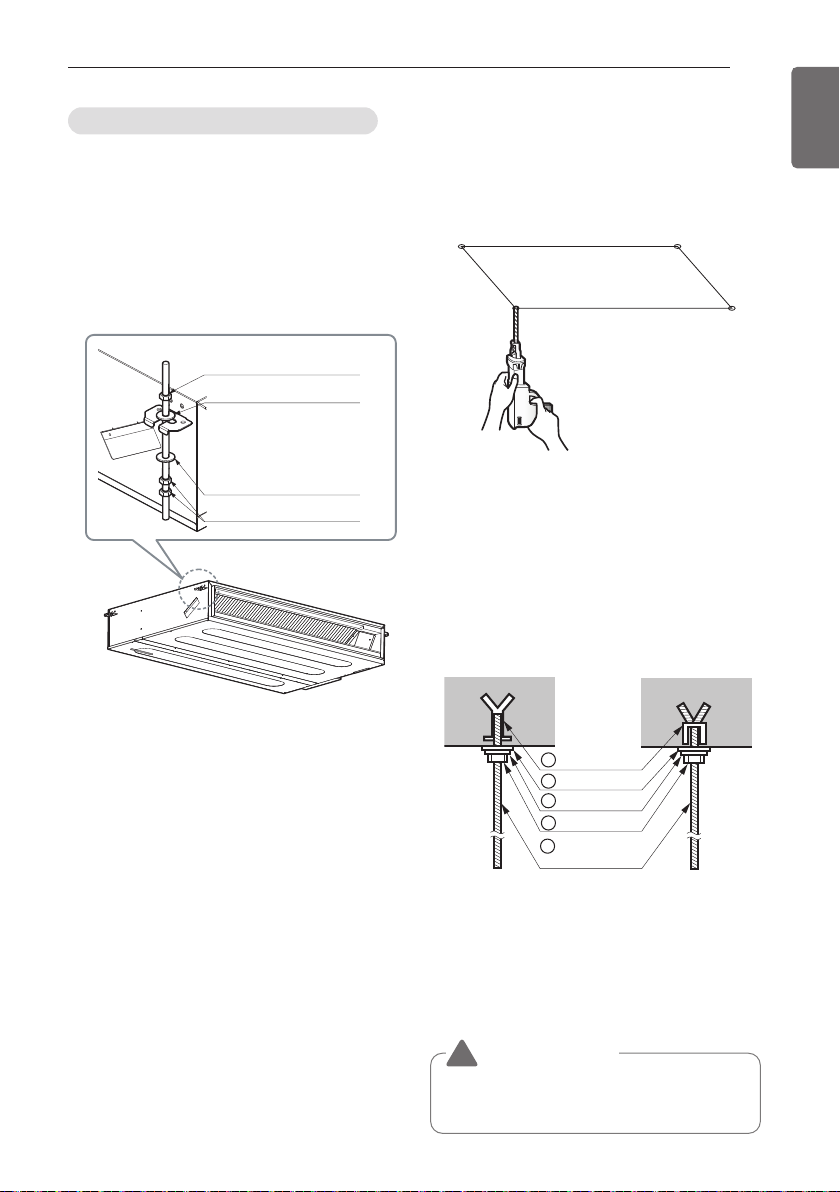
INSTALLATION
M10 Nut
M10 washer
X 4
X 4
M10 Nut
M10 washer
X 4
X 8
1 Set anchor
Old building New building
2 Plate washer
3 Spring washer
4 Nut
5 Suspension
bolts
9
ENGLISH
POSITION OF CONSOLE BOLT
- A place where the unit will be leveled and
that can support the weight of the unit.
- A place where the unit can withstand its
vibration.
- A place where service can be easily
performed.
Indoor Unit Installation
- Select and mark the position for fixing bolts.
- Drill the hole for set anchor on the face of
ceiling.
- Insert the set anchor and washer onto the
suspension bolts for locking the suspension
bolts on the ceiling.
- Mount the suspension bolts to the set
anchor firmly.
- Secure the installation plates onto the
suspension bolts (adjust level roughly) using
nuts, washers and spring washers.
• Local supply
① Set anchor
② Plate washer - M10
③ Spring washer - M10
④ Nut - W3/8 or M10
⑤ Suspension bolt - W3/8 or M10
CAUTION
!
Tighten the nut and bolt to prevent unit
falling.
 Loading...