

LG LG18K11 User Manual
MULTI
F
MAX
MULTI
F
Multi-Zone Heat Pump Systems
1.5 to 4.5 Tons
HEAT PUMP SYSTEM
ENGINEERING MANUAL
Dual and Tri-Zone
Multi F
Quad-Zone
Multi F
Eight-Zone
Multi F MAX

PROPRIETARY DATA NOTICE
This document, as well as all reports, illustrations, data, information, and
other materials are the property of LG Electronics U.S.A., Inc., and are
disclosed by LG Electronics U.S.A., Inc., only in confidence.
This document is for design purposes only.
EM-MultiFODU-01-15
For continual product development, LG reserves the right to change specifications without notice.
©LG Electronics Inc.
This document, as well as all reports, illustrations, data, information, and other materials are the property of LG Electronics U.S.A., Inc.
MULTI
MAX
MULTI
F
TABLE OF CONTENTS
DANGER
WARNING
CAUTION
About LG Electronics, Inc. .................................................................... 4
Multi-Zone Systems ............................................................................... 4
Unit Nomenclature ................................................................................. 6
Outdoor Unit Overview ......................................................................... 7
Indoor Unit Overview ............................................................................ 8
Controls and Options Overview ...................................................... 9-13
Multi F Outdoor Unit Product Data ............................................. 15-286
Product Features and Benets .......................................................... 16
Mechanical Specications ................................................................. 17
General Data ................................................................................ 18-19
Dimensions ................................................................................... 20-22
Rated Cooling Combination Tables .............................................. 23-30
Rated Heating Combination Tables .............................................. 31-38
Cooling Capacity Tables ............................................................. 39-182
Heating Capacity Tables ........................................................... 183-278
Electrical Data ................................................................................. 279
Acoustic Data .................................................................................. 279
Refrigerant Flow Diagrams ....................................................... 280-282
Wiring Diagrams ....................................................................... 283-285
Operation Range ............................................................................. 286
Multi F MAX Outdoor Unit Product Data ..................................287-330
Product Features and Benets ........................................................ 288
Mechanical Specications ............................................................... 289
General Data ............................................................................ 290-291
Dimensions ...................................................................................... 292
Rated Cooling Combination Tables .......................................... 293-295
Rated Heating Combination Tables .......................................... 296-298
Cooling Capacity Tables ........................................................... 299-315
Heating Capacity Tables ........................................................... 316-326
Electrical Data ................................................................................. 327
Acoustic Data .................................................................................. 327
Refrigerant Flow Diagrams .............................................................. 328
Wiring Diagrams .............................................................................. 329
Operation Range ............................................................................. 330
Multi F MAX Branch Distribution Unit Product Data ...............331-340
Features and Benets ..................................................................... 332
Mechanical Specications ............................................................... 333
General Data ................................................................................... 334
Dimensions ...................................................................................... 335
Refrigerant Flow Diagram ................................................................ 336
Wiring Diagram ................................................................................ 337
Y-Branch Accessory ......................................................................... 338
Branch Distribution Unit Orientation ................................................ 339
Application Guidelines ............................................................... 341-358
Equipment Selection Procedure ............................................... 342-347
Building Ventilation Design Guide ............................................348-352
Placement Considerations ........................................................ 353-358
Refrigerant Piping Design & Layout Best Practices ............... 359-380
Design Guideline Summary ...................................................... 360-361
Creating a Balanced / Quality Piping System .................................. 362
Manual Layout Procedure ............................................................... 362
LG Engineered Multi F MAX Y-Branch Kits ..................................... 363
Refrigerant Charge ................................................................... 364-365
Selecting Field-Supplied Copper Tubing ..................................366-367
Refrigerant Piping System Layout ............................................ 368-375
Piping Insulation .............................................................................. 376
Condensate Drain Piping .......................................................... 377-378
Cut Sheet ......................................................................................... 379
Wiring Connections .................................................................... 381-390
General Information .................................................................. 382-384
Power Wiring and Communications Cable Details ................... 385-389
Indoor Unit Group Control ............................................................... 390
Acronyms ........................................................................................... 391
Introduction
TABLE OF SYMBOLS
Note:
This symbol indicates an imminently hazardous situation which, if not avoided, will result in death or
serious injury.
This symbol indicates a potentially hazardous situation which, if not avoided, could result in death or
serious injury.
This symbol indicates a potentially hazardous situation which, if not avoided, may result in minor or
moderate injury.
This symbol Indicates situations that may result in equipment or property damage accidents only.
This symbol indicates an action that should not be performed.
INTRODUCTION | 3
CONVERGENCE OF TECHNOLOGY,
MULTI
F
INNOVATION, FLEXIBILITY, & STYLE
About LG Electronics, Inc.
LG Electronics, Inc. is a global leader and technology innovator
in consumer electronics, mobile communications, and home
appliances, employing more than 213,000 people in more than 60
countries worldwide. LG Electronics, Inc. comprises five
business units—Home Entertainment, Mobile Communications, Air
Conditioning, Business Solutions, and Home Appliance. LG is one
of the world’s leading producers of flat panel televisions, audio and
video products, mobile handsets, air conditioners, and washing
machines. LG’s commercial air conditioning business unit was established in 1968 and has built its lineup of residential and commercial
products to include VRF, Multi F, duct-free split systems, packaged
terminal air conditioners (PTACs), and room air conditioners. In
2011, the air conditioning and energy solutions business unit grew to
include LED lighting and solar products. For more information, visit
www.lg-dfs.com.
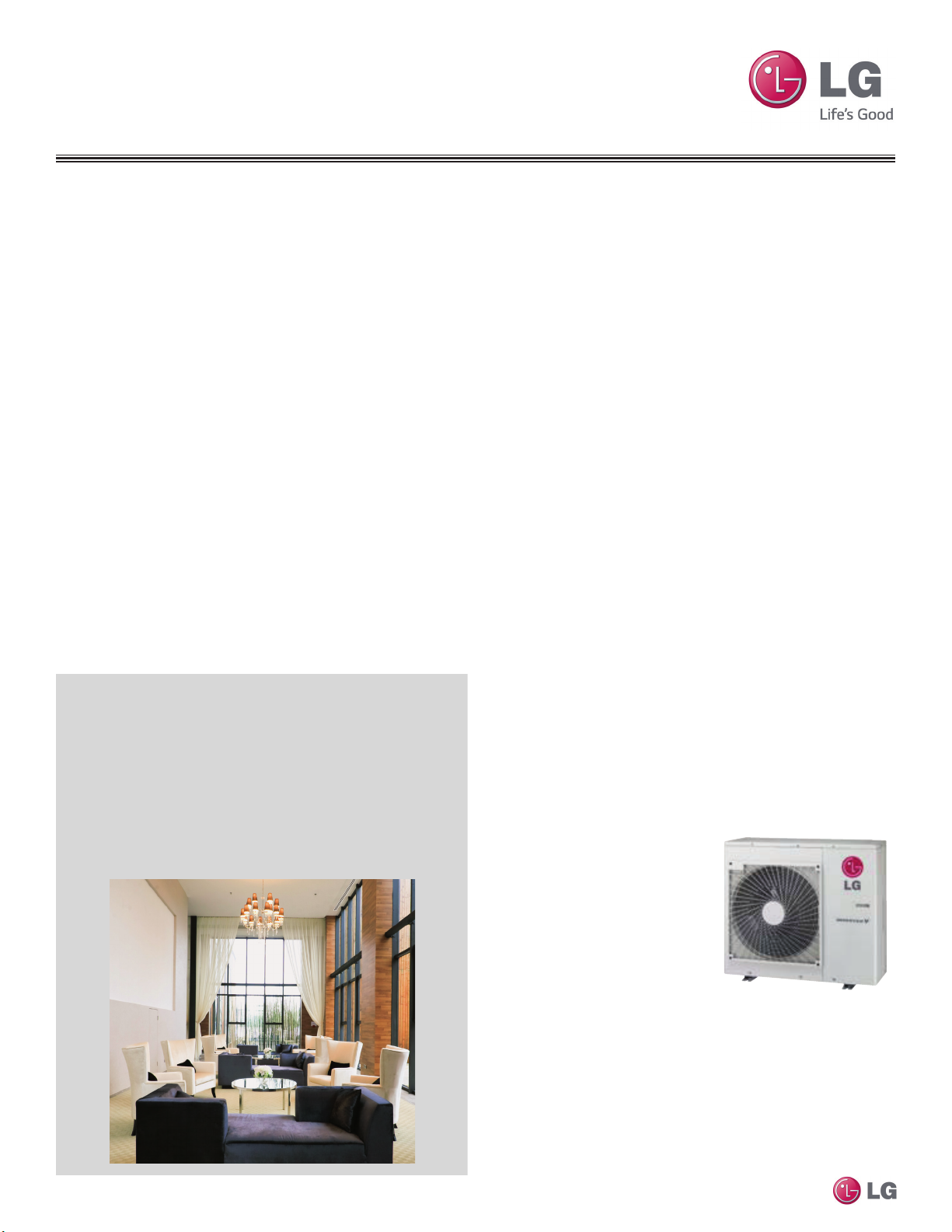
Multi-Zone Systems
LG HVAC systems offer a range of solutions that are cost efficient,
quiet and attractive. Multi-zone systems are “split” into indoor and
outdoor units, and provide a smart alternative to both central HVAC
and window-mounted air conditioners. These inverter heat pump
systems are available in a variety of configurations to suit different cooling and heating situations. Installation by a qualified HVAC
contractor is safe and easy – little to no duct work or sheet metal is
required.
Multi F Systems
LG’s inverter heat pumps can support two, three, or four indoor
units that are typically installed in separate rooms. Each indoor unit
includes its own remote control, allowing the customer to set the
temperature individually. Indoor units are available in several differ-
ent congurations: Art Cool™ Mirror wall-mounted, Art Cool Gallery
wall-mounted, standard wall-mounted, four-way ceiling cassettes,
ceiling-concealed duct (high and low static), and vertical-horizontal air
handling models. Multi F MAX systems, released in 2012, can operate up to eight indoor units through two-, three-, or four-port branch
distribution units.
Adaptable and Flexible
Multi F outdoor units can be adapted to a wide range of building ap-
plications and sizes such as schools, hotels, hospitals, ofces, and
residences. The system components are lightweight and compact so
they can be placed in buildings without expensive cranes, they easily
fit into most service elevators, and they can be set in place with
minimal structural reinforcements requirements.
Multi F technology allows you to pipe farther by reaching areas of the
building that would require the installation of a second system when
using traditional direct-expansion cooling and heating equipment. Multi
F provides the designer with uncompromised pipe system engineering
exibility—long pipe runs and large elevation differences. Whether your
building is a condominium, a hotel, a school, or an ofce complex, Multi
F is best suited to reach the farthest corners and elevations.
Smaller Chases and Plenums
Benefits of Multi F Systems
• Individual zone control
• Long refrigerant piping lengths
• High refrigerant piping elevation differences
• Maximum flexibility
• Operating ranges of 14°F to 118°F (DB) in cooling and -4°F to
64°F (WB) in heating
• Quiet and comfortable environment
• Reduced ductwork
Multi F and Multi F MAX Indoor Unit Engineering Manual
LG Multi F systems use refrigerant piping to move heat, resulting in
smaller space requirements for piping as compared to chilled water
or roof top systems. This helps reduce the overall construction and
material cost of the building, and gives back leasable space. Flexible
and logical placement of system components, reduced back-andforth pipe lengths, and fewer joints lowers installation costs and
minimizes potential leaking.
Quality Commitment
LG is committed to the success
of DFS projects. We provide
technical support during installation and commissioning. LG
offers a variety of classes
designed for installers and on
Multi F installation. Classes
are conducted at LG’s training
centers and in field locations
at various times throughout the
year and upon special request.
4 | INTRODUCTION
Due to our policy of continuous product innovation, some specications may change without notication.
©LG Electronics U.S.A., Inc., Englewood Cliffs, NJ. All rights reserved. “LG” is a registered trademark of LG Corp.

PRODUCT
INTRODUCTION
“Unit Nomenclature” on page 6
“Outdoor Unit Overview” on page 7
“Indoor Unit Overview” on page 8
“Controls and Options Overview” on page 9
MULTI
F
MAX
MULTI
F
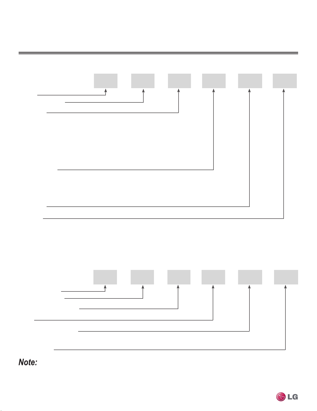
UNIT NOMENCLATURE
Multi-Zone Systems — Indoor Units and Outdoor Units
L
L = LG
Type: M = Multi-Zone
Component:
AN: Art Cool™ Wall-Mounted Indoor Unit
N: Standard Wall-Mounted Indoor Unit
CN: Four-Way Ceiling-Cassette Indoor Unit
DN: Ceiling-Concealed Duct (Low Static) Indoor Unit
HN: Ceiling-Concealed Duct (High Static) Indoor Unit
VN: Vertical-Horizontal Air Handling Indoor Unit
U: Outdoor Unit
Nominal Capacity
(Nominal cooling capacity in Btu/h):
07 = 7,000
09 = 9,000
12 = 12,000
Generation
Features:
H = Heat Pump
V = Inverter
T = High Wall-Mounted Indoor Unit
P = Art Cool Gallery Indoor Unit
15 = 15,000
18 = 18,000
24 = 24,000
36 = 36,000
54 = 54,000
M
AN 12 7 HVT
Branch Distribution Units
P
P = Part (Accessory)
Multi F and Multi F MAX Indoor Unit Engineering Manual
Type: M = Multi-Zone
BD: Branch Distribution Unit
Family
Number of Port Connections
(Maximum Number of Connectable Indoor Units): 2, 3, 4
Generation: 0, 1
• Voltage for all equipment is 208-230V, 60 Hz, 1-phase.
• All indoor units are compatible with wired controllers
• All outdoor units are LGAP control network compatible with PI-485 V-net Control Integration Board (PMNFP14A1, sold separately).
• Compatible single zone IDU nomenclature is listed in the Single Zone Wall-Mounted IDU Engineering Manual.
6 | INTRODUCTION
Due to our policy of continuous product innovation, some specications may change without notication.
©LG Electronics U.S.A., Inc., Englewood Cliffs, NJ. All rights reserved. “LG” is a registered trademark of LG Corp.
M
BD 36
02
MULTI
F
MAX
MULTI
F
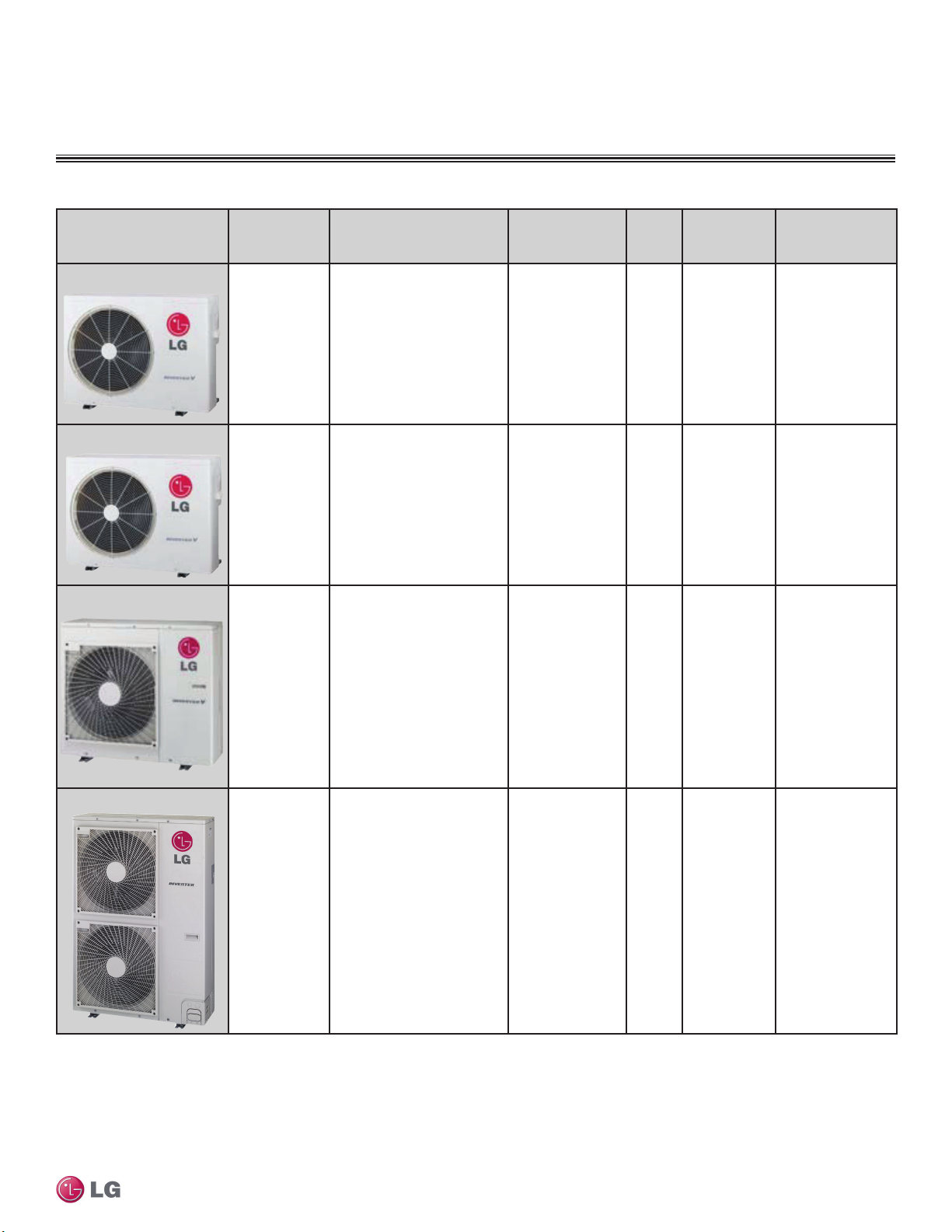
Table 1: Summary Data—Multi F / Multi F MAX Outdoor Units
Dimensions
(W x H x D)
Outdoor Unit Type Model Number
Multi F Dual-Zone
1
(inches)
OUTDOOR UNIT OVERVIEW
Nominal Cooling
Capacity Btu/h
2
Net
Weight
(lbs.)
No. of
Connectable
Indoor Units
Pipe Connections
(inches, O.D.)
3
(Liquid, Vapor)
Multi F Tri-Zone
Multi F Quad-Zone
LMU18CHV 34-1/4 x 25 25/32 x 12-19/32 18,000 100 2-2
LMU24CHV 34-1/4 x 25 25/32 x 12-19/32 24,000 100 2-3
LMU36CHV 37-13/32 x 32-27/32 x 13 36,000 137 2-4
1/4 x 2 Each,
3/8 x 2 Each
1/4 x 3 Each,
3/8 x 3 Each
Introduction
1/4 x 4 Each,
3/8 x 4 Each
1
2
3
Multi F MAX Eight-Zone
LMU540HV 37-13/32 x 54-11/32 x 13 54,000 214 2-8
Model number shows nominal capacity and frame size designator.
Nominal capacity rating obtained with air entering the indoor unit at 80ºF dry bulb (DB) and 67ºF wet bulb (WB) and outdoor ambient conditions of 95ºF dry bulb (DB) and 75ºF wet bulb (WB).
Minimum number of connectable indoor units is two (2).
Due to our policy of continuous product innovation, some specications may change without notication.
©LG Electronics U.S.A., Inc., Englewood Cliffs, NJ. All rights reserved. “LG” is a registered trademark of LG Corp.
INTRODUCTION | 7
3/8 x 1 Each,
3/4 x 1 Each
MULTI
F
MAX
MULTI
F
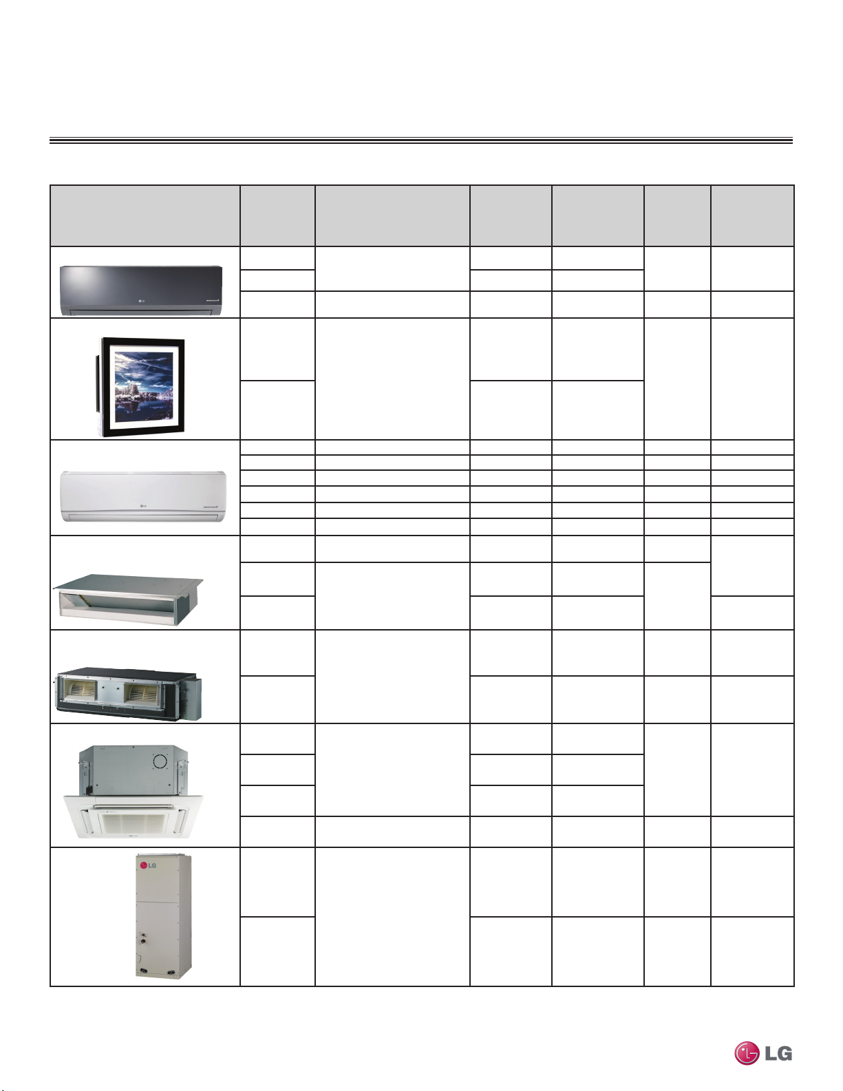
INDOOR UNIT OVERVIEW
Table 2: Summary Data—Multi F Indoor Units.
Dimensions
(W x H x D)
(inches)
35-1/4 × 11-3/8 × 8-1/16
Indoor Unit Type
TM
Art Cool
Art CoolTM Gallery Wall-Mounted
Mirror Wall-Mounted
Model
1
Number
LMAN097HVT
LMAN127HVT 12,000 335 / 318 / 300
LMAN187HVT 40-9/16 x 12-25/32 x 9-21/32 18,000 572 / 501 / 434 35 1/4, 1/2
LMAN097HVP
Nominal
Cooling
Capacity Btu/h
9,000 247 / 230 / 212
9,000 272 / 208 / 155
Air Flow Rate
2
(CFM)
(H/M/L3)
Net
Weight
(lbs.)
25 1/4, 3/8
Connections
(inches, O.D.)
(Liquid, Vapor)
Pipe
23-5/8 x 23-5/8 x 5-25/32
LMAN127HVP 11,200 314 / 258 / 198
Standard Wall-Mounted
Ceiling-Concealed Duct
(Low Static)
Ceiling-Concealed Duct
(High Static)
Four-Way Ceiling-Cassette
Multi F and Multi F MAX Indoor Unit Engineering Manual
VerticalHorizontal
Air Handling
LMN077HVT 35-1/4 x 11-3/8 x 8-9/32 7,000 198 / 177 / 162 23 1/4, 3/8
LSN090HSV4 34-7/8 x 11-1/4 x 8-1/4 9,000 247 / 230 / 212 20 1/4, 3/8
LSN120HSV4 34-7/8 x 11-1/4 x 8-1/4 12,000 335 / 318 / 300 20 1/4, 3/8
LMN157HVT 35-1/4 x 11-3/8 x 8-9/32 14,300 371 / 318 / 247 23 1/4, 3/8
LSN180HSV4 40-9/16 x 12-13/16 x 9-13/16 18,000 572 / 501 / 434 31 3/8, 5/8
LMN247HVT 40-9/16 x 12-25/32 x 9-27/32 24,000 720 / 600 / 466 32 1/4, 1/2
LMDN096HV 27-9/16 x 7-15/32 x 27-9/16 9,000 318 / 247 / 194 39
LMDN126HV
35-7/16 x 7-15/32 x 27-9/16
LMDN186HV 18,000 530 / 441 / 353 1/4, 1/2
LMHN240HV
46-17/32 x 11-23/32 x 17-23/32
LMHN360HV 36,000 1,130 / 953 / 706 91 3/8, 5/8
LMCN077HV
Body: 22-7/16 x 8-7/16 x 22-7/16
Panel: 27-9/16 x 7/8 x 27-9/16
LMCN125HV 12,000 335 / 283 / 247
LMCN185HV
LMVN240HV
Body: 22-7/16 x 10-3/32 x 22-7/16
Panel: 27-9/16 x 7/8 x 27-9/16
12,000 353 / 300 / 247
24,000 688 / 618 / 530 80 1/4, 1/2
7,000 265 / 212 / 177
18,000 459 / 424 / 388
24,000 710 / 640 / 480 117 1/4, 1/2
32 1/4, 3/8
51
31 (Body),
7 (Panel)
34 (Body),
7 (Panel)
1/4, 3/8
1/4, 3/8LMCN097HV 9,000 300 / 265 / 230
1/4, 1/2
1
2
3
8 | INTRODUCTION
18 x 48-21/32 x 21-1/4
LMVN360HV 36,000 990 / 880 / 800 121 3/8, 5/8
Model number shows nominal capacity and frame size designator.
Nominal capacity rating obtained with air entering the indoor unit at 80ºF dry bulb (DB) and 67ºF wet bulb (WB) and outdoor ambient conditions of 95ºF dry bulb (DB) and 75ºF wet bulb (WB).
H/M/L = High/Medium/Low.
Due to our policy of continuous product innovation, some specications may change without notication.
©LG Electronics U.S.A., Inc., Englewood Cliffs, NJ. All rights reserved. “LG” is a registered trademark of LG Corp.
MULTI
F
MAX
MULTI
F
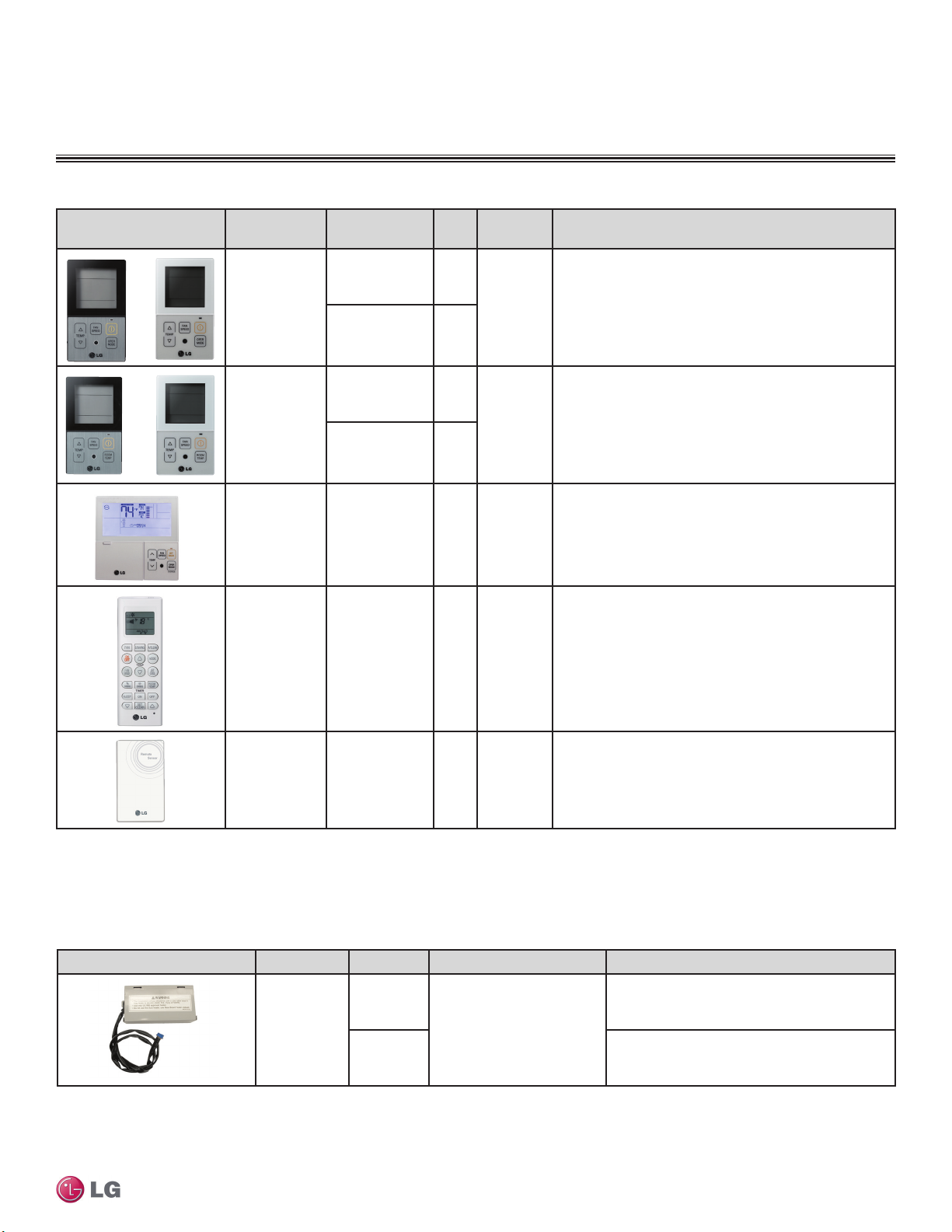
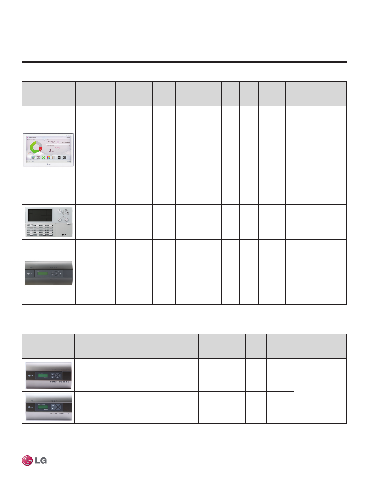
CONTROLS AND OPTIONS OVERVIEW
Table 3: Summary Data—Zone Controllers.
Zone Controller Name Model / Part No.
Case
Color
Max. Wire
Length (ft.)
Description
Simple Controller
with Mode
Selection
Simple Controller
without Mode
Selection
LG 7-Day
Programmable
Thermostat
Wireless
Controller
PQRCVCL0Q Black
1
AKB72955816
PQRCHCA0 Black
PQRCHCA0QW White
PREMTB10U White 164
AKB73635606
AKB73635607
AKB73835312
AKB73757604
White
3
4
Ivory -
5
6
164
164
Allows control of indoor unit ON / OFF, operation mode, fan
speed, and temperature setpoint for up to 16 indoor units.
Included with Ceiling-Concealed Duct (High Static and Low
1
) and Vertical-Horizontal Air Handling1 indoor units;
Static
optional accessory for all other indoor unit types.
Allows control of indoor unit ON / OFF, fan speed, and
temperature setpoint for up to 16 indoor units.
Allows control of indoor unit ON / OFF, operation mode,
occupied / unoccupied temperature setpoints, fan speed, and
airflow direction for up to 16 indoor units. Programmable
schedule with five events per day.
Allows control of indoor unit ON / OFF, operation mode, fan
speed, and temperature setpoint. Also provides subfunction
control. Included with Art Cool Mirror
Mounted, Standard HVT
Wall-Mounted, and Four-Way Cassette
accessory for Duct and Vertical-Horizontal AHU with use of
wired controller.
3
Wall-Mounted, Standard HSV5
3
and Gallery4 Wall-
6
indoor units; optional
Introduction
1
Before specifying or placing an order, refer to the V-Net Network Solutions Engineering Product Data Book, and review the detailed technical data provided to fully understand the capabilities and limitations of
these devices.
For information on controller capatibility, refer to the Controls and Options Table on page 12
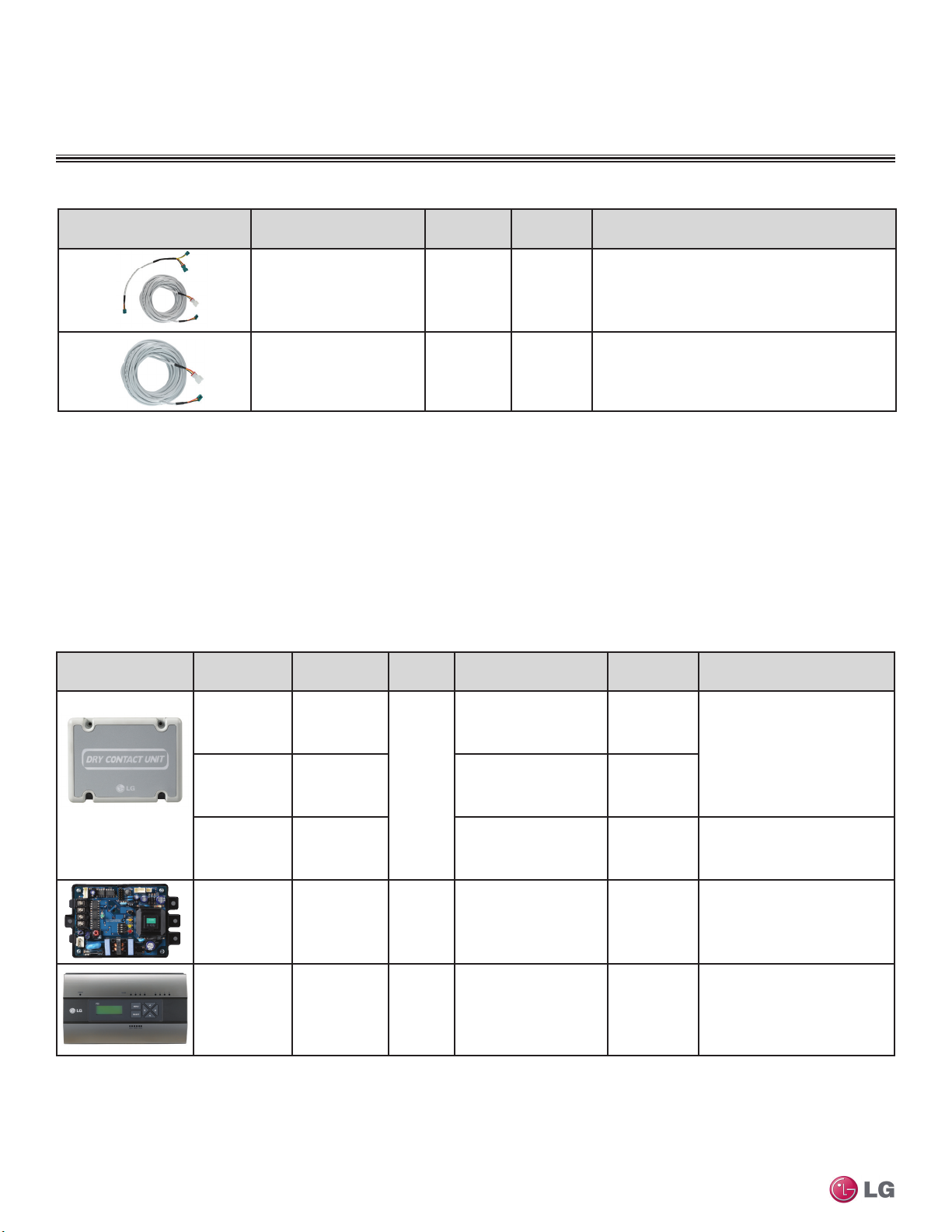
Table 4: Summary Data—Controller Accessories.
Wall-Mounted
Remote
Temperature
Sensor
Simple Mode Controllers for the ceiling-concealed duct (high static and low static) and the vertical-horizontal air handling indoor units are also referenced by Model No. PQRCVCL0QW.
PQRSTA0 Ivory 50
Allows remote temperature measurement for four-way ceiling
cassette, ceiling-concealed duct, and vertical-horizontal air
handling indoor units.
Controller Accessory Name Model No. Description For
Adds coordinated control of
PRARH0
Auxiliary Heater
Relay Kit
PRARS0
Due to our policy of continuous product innovation, some specications may change without notication.
©LG Electronics U.S.A., Inc., Englewood Cliffs, NJ. All rights reserved. “LG” is a registered trademark of LG Corp.
an external heater with normal
heat pump operations. Contact
energizes at 2.7°F below
setpoint. De-energizes at
2.7°F above setpoint.
Ceiling-concealed duct (high static and low static)
and four-way ceiling cassette indoor units.
Standard and Art Cool Mirror wall-mounted indoor
units.
INTRODUCTION | 9
MULTI
F
MAX
MULTI
F
CONTROLS AND OPTIONS OVERVIEW
Table 5: Summary Data— Zone Controller Communication Cables.
Communication Cable Name Model No.
Max. Wire
Length (ft.)
Description
Wired Remote Group Control
Cable Assembly
Wired Remote / Group Control
Extension Cable
Before specifying or placing an order, refer to the V-Net Network Solutions Engineering Product Data Book, and review the detailed technical data provided to fully understand the capabilities and limitations of
these devices.
For information on controller capabilities, refer to the Controls and Options Table on page 12.
Table 6: Summary Data—Specialty Application Devices.
Specialty Application
Device
Name Model No.
Dry Contact Unit
24 VAC
Dry Contact Unit
for Setback
PQDSB1
PQDSBC
PZCWRCG3 32
PZCWRC1 32
Connects
to
ON / OFF, Run Status,
Error Status
Indoor
Unit
ON / OFF, Mode, Controller
Lock, Power Save, Run
Status, Error Status
Application
Required when grouping multiple indoor units with a
single zone controller.
Increases the distance between a remote controller
and an indoor unit, or between indoor units in a control
group.
Binary Signals
Input / Output
1 / 2
2 / 2
Enables the indoor unit to be
controlled and monitored by
third-party controls using
binary inputs and outputs.
Description
Dry Contact Unit
for Thermostat
Multi F and Multi F MAX Indoor Unit Engineering Manual
Before specifying or placing an order, refer to the V-Net Network Solutions Engineering Product Data Book, and review the detailed technical data provided to fully understand the capabilities and limitations of
these devices.
For information on controller capabilities, refer to the Controls and Options Table on page 12.
10 | INTRODUCTION
PI-485 V-net
Control
Integration
Board
Power
Distribution
Indicator (PDI)
Premium
PQDSBNGCM1
PMNFP14A1
PQNUD1S41
Due to our policy of continuous product innovation, some specications may change without notication.
©LG Electronics U.S.A., Inc., Englewood Cliffs, NJ. All rights reserved. “LG” is a registered trademark of LG Corp.
Outdoor
Unit
Comm.
BUS
ON / OFF, Thermo ON /
OFF, Mode, Fan Speed,
Run Status, Error Status
Energy Consumption
Monitoring
— —
8 / 0
Enables the indoor unit to be
—
controlled and monitored by a
third-party thermostat or controller.
Control integration to LG V-net
controls (AC Smart Premium, ACP,
BACnet, LonWorks, etc.)
Monitors total outdoor unit power
consumption for up to eight
systems, and distributes per
indoor unit based on weighted
calculation.
MULTI
F
MAX
MULTI
F
CONTROLS AND OPTIONS OVERVIEW
Table 7: Summary Data—Central Controllers (Connect to the Outdoor Unit Through the PI-485 Board (accessory, sold separately).
Central Controller Name Model No.
AC Smart
Premium
PQCSW421E0A 128 16 128 1
Devices
per
Controller
Systems
per
Comm.
BUS
Devices
per Comm.
BUS
No. of
Comm.
BUS
ports
Binary
Signals
Input /
Output
2 DI /
2 DO
Power /
Connection
24 VAC
Provides for scheduling,
auto-changeover, setback,
remote controller lock,
setpoint range limit, run
time limit, web access,
email alarm notification,
visual floorplan navigation,
peak/demand control,
software device interlocking,
PDI integration, and AC
Manager Plus integration
advanced functionality in
addition to basic unit control
and monitoring.
Description
12 VDC /
AC Ez PQCSZ250S0 32 16 256 1 —
Advanced Control
Platform (ACP)
Standard
Advanced Control
Platform (ACP)
Premium
Before specifying or placing an order, refer to the V-Net Network Solutions Engineering Product Data Book, and review the detailed technical data provided to fully understand the capabilities and limitations of
these devices.
For information on controller capabilities, refer to the Controls and Options Table on page 12.
Table 8: Summary Data—Integration Solutions (Connect to Outdoor Unit Through the PI-485 Board (accessory, sold separately).
Central Controller Name Model No.
BACnet® Gateway PQNFB17C1 256 16
®
LonWorks
Gateway PLNWKB100 64 16
PQCPC22N1 256 16
PQCPC22A1 256 16
per
Systems
Comm.
BUS
Devices
Controller
per
64 (128
with PDI
Premium)
64 (128
with PDI
Premium)
Devices
per Comm.
BUS
64 (128
with PDI
Premium)
64 (128
with PDI
Premium)
2 / 2 24 VAC
4
10 / 4 24 VAC
No. of
Comm.
BUS
ports
4 2 / 2 24 VAC
1 2 / 2 24 VAC
Binary
Signals
Input /
Output
Outdoor
Unit
Connection
Provides for scheduling in
addition to basic indoor unit
control and monitoring.
Provides for scheduling,
remote controller lock, setpoint
range limit, web access, peak
/ demand control, PDI
integration, and AC Manager
Plus integration advanced
functionality in addition to
basic unit control and
monitoring.
Power /
Description
Allow integration of LG
equipment for control
and monitoring by open
protocol BACnet and
LonWorks building
automation and controls
systems.
Introduction
Before specifying or placing an order, refer to the V-Net Network Solutions Engineering Product Data Book, and review the detailed technical data provided to fully understand the capabilities and limitations of
these devices.
For information on controller capabilities, refer to the Controls and Options Table on page 12.
Due to our policy of continuous product innovation, some specications may change without notication.
©LG Electronics U.S.A., Inc., Englewood Cliffs, NJ. All rights reserved. “LG” is a registered trademark of LG Corp.
INTRODUCTION | 11
MULTI
F
MAX
MULTI
F
CONTROLS AND OPTIONS OVERVIEW
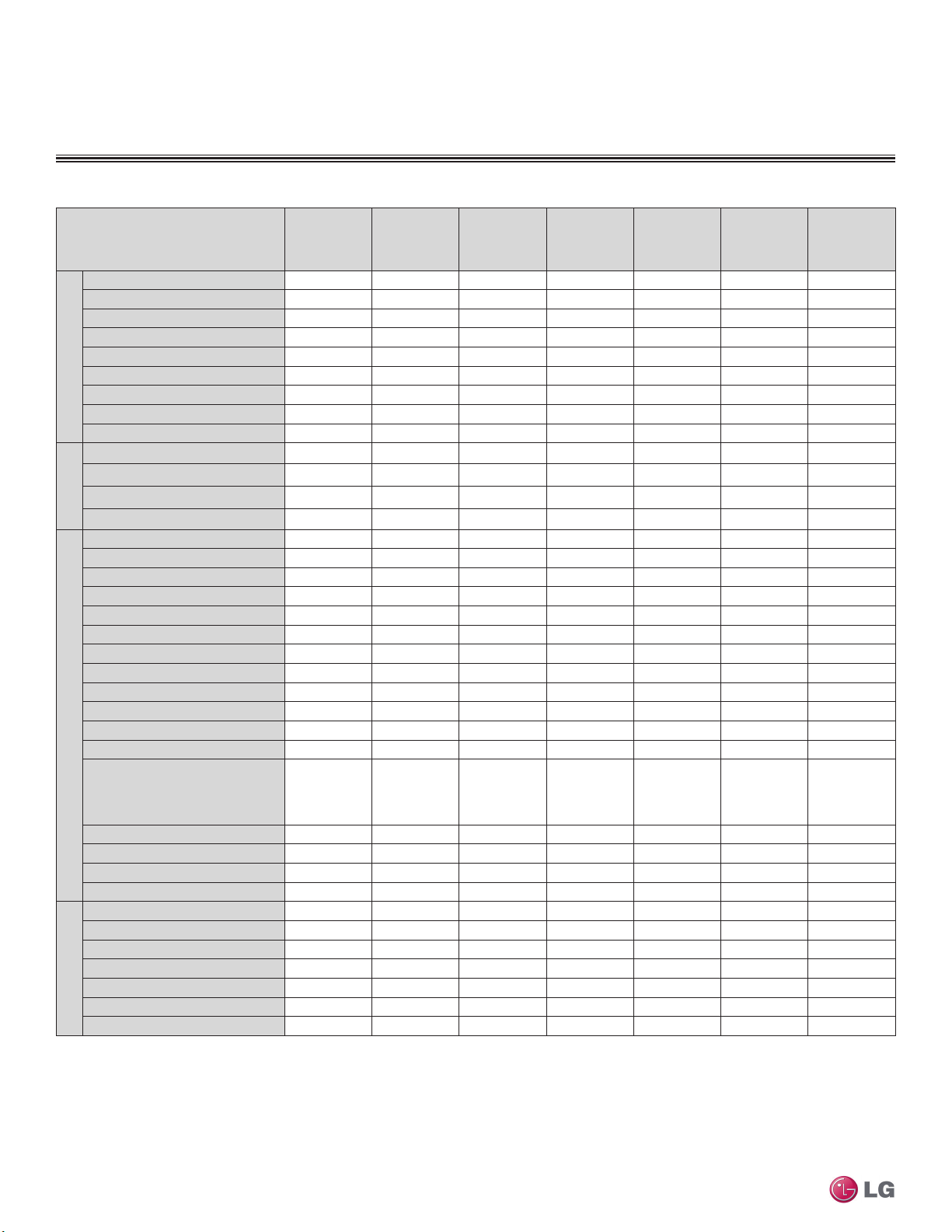
Table 9: Indoor Units—Functions, Controls and Options.
ART COOL™
Indoor Unit Type
Mirror Wall
Mounted
Air supply outlets
Airflow direction (left/right)
Airflow direction (up/down)
Auto swing (left/right)
Auto swing (up/down)
Airow
Airflow steps (fan/cool/heat)
Chaos wind (random fan speed)
Jet-cool
1 3 1 1 2 4 1
Auto Auto Auto
Auto Auto Auto Auto
√ √ √
√ √ √ √
6 / 6 / 5 5 / 5 / 4 6 / 6 / 5 3 / 3 / 3 3 / 3 / 3 4 / 5 / 4 3 / 3 / 3
√ √ √ √
√ √ √ √
Swirl wind
Washable anti-fungal
2
Plasma
Filter
3M HAF
2
1
√ √ √ √ √ √
√ √ o
Ventilation
Drain pump
E.S.P. control
Electric heater
High ceiling
Hot Start
Self diagnostics
Soft Dry (dehumidification)
Auto operation
Auto clean (coil dry)
Auto restart
Child lock
Operation
Forced operation
√ √ √ √ √ √ √
√ √ √ √ √ √ √
√ √ √ √ √ √ √
√ √ √ √ √ √ √
√ √ √
√ √ √ √ √ √ √
o o o o o o o
√ √ √ √
Group control – Requires the use
of one Group control Cable Kit
(PZCWRCG3) for every
o o o o o o o
additional indoor unit
Sleep mode
Timer (on/off)
Weekly schedule
Multi F and Multi F MAX Indoor Unit Engineering Manual
Two thermistor control
7-Day programmable controller
Simple wired remote controller
Wireless LCD remote control
Dry contact
Dry contact (temperature setting)
Controllers
Central control (LGAP)
Connector for Water Sensor
1
Primary washable filters.
2
Secondary filter (plasma: HVT wall-mount and cassette; 3M: HSV4)
3
Branch location and static pressure requirements. Requires PTPKQ0
Plasma kit.
√ √ √ √ √ √ √
√ √ √ √ √ √ √
o o o √ √ o √
o o o o o o o
o o o o o o o
o o o √ √ o √
√ √ √ o
o o o o o o o
o o o o o o o
√ √ √ √ √ √ √
√ √ √
ART COOL™
Gallery
4
Requires ventilation kit PTVK430 (Temperature, humidity, and volume
limitations apply).
5
Requires wired zone controller.
Standard Wall
Mounted
√
Concealed
(Low Static)
Ceiling
Ducted
√ √ √
√ √ √
5
Ceiling
Concealed
(High Static)
Ducted
5
o
Four-Way
Ceiling
Cassette
√
3
4
√
√
√ o
√ = Standard feature
o = Unit option
VerticalHorizontal Air
Handling Unit
o
5
12 | INTRODUCTION
Due to our policy of continuous product innovation, some specications may change without notication.
©LG Electronics U.S.A., Inc., Englewood Cliffs, NJ. All rights reserved. “LG” is a registered trademark of LG Corp.
MULTI
F
MAX
MULTI
F
CONTROLS AND OPTIONS OVERVIEW
Ø3/4 Gas
Ø3/8 Liquid
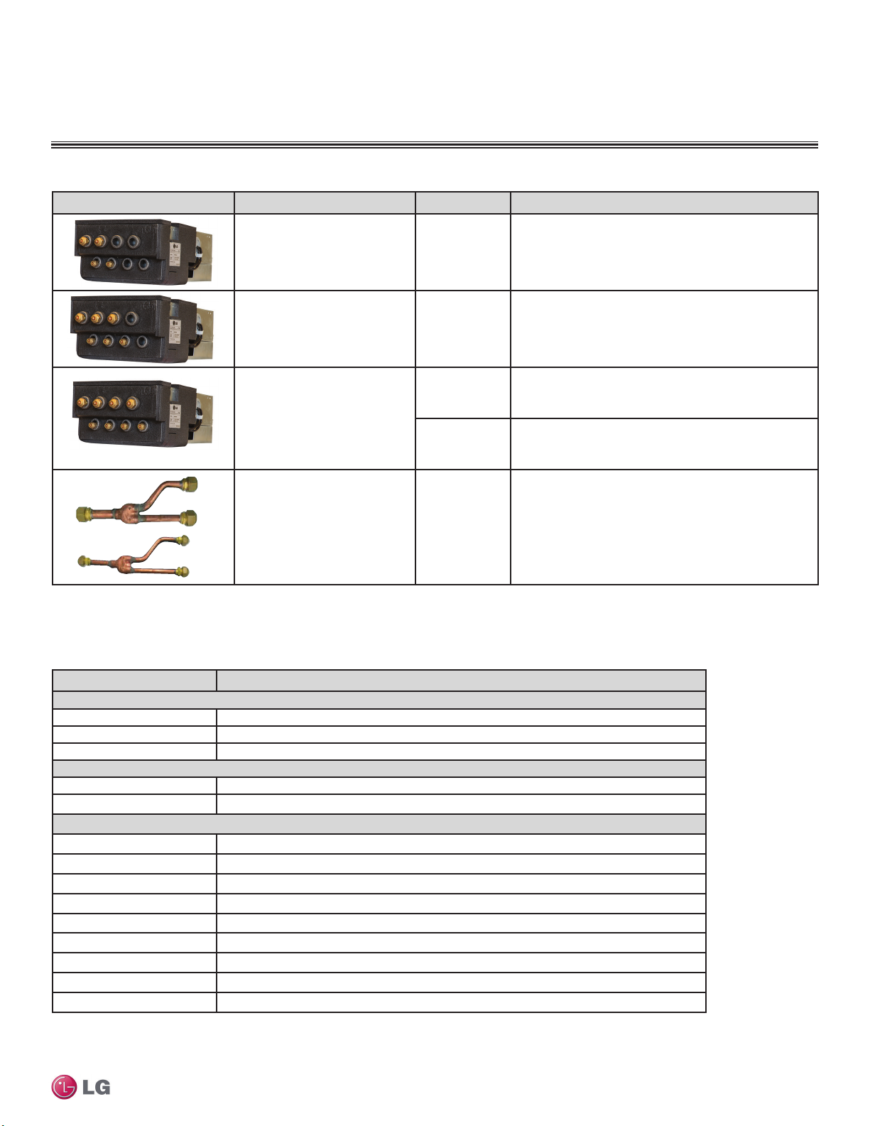
Table 10: Multi F MAX Outdoor Unit Accessories Overview.
Multi F MAX Accessory Name Model No. Description
Distributes refrigerant from Multi F MAX outdoor unit from
Two-Port Branch Distribution Unit PMBD3620
Three-Port Branch Distribution Unit PMBD3630
PMBD3640
Four-Port Branch Distribution Unit
PMBD3641
one (1) to two (2) indoor units (maximum 24,000 Btu/h for
each port).
Distributes refrigerant from Multi F MAX outdoor unit from
one (1) to three (3) indoor units (maximum 24,000 Btu/h for
each port).
Distributes refrigerant from Multi F MAX outdoor unit from
one (1) to four (4) indoor units (maximum 24,000 Btu/h for
each port).
Distributes refrigerant from Multi F MAX outdoor unit from
one (1) to four (4) indoor units (maximum 24,000 Btu/h for
ports A,B,C; maximum 36,000 Btu/h for D port).
Y-branch Kit PMBL5620
Table 11: Indoor Unit Accessories Overview.
Model No. Description
For Four-Way Ceiling-Cassette Indoor Units
PT-UQC Ceiling Grille
PTPKQ0 Plasma Kit
PTVK430 Ventilation Kit
For Vertical-Horizontal Air Handing Units
ANEH053B1 5 kW Electric Heater
ANEH103B2 10 kW Electric Heater
For Ceiling-Concealed Duct (High Static) Indoor Units
ZFBXBG01A High Efficiency Filter Box
ZFBXD201A Dynamic V8 2VL Low Profile Air Cleaner
ZPLMV201A Dynamic 2VL Air Cleaner Low Profile Return Air Plenum
ZFBXD402A Dynamic V8 4VL Low Profile Air Cleaner
ZPLMV402A Dynamic 4VL Air Cleaner Low Profile Return Air Plenum
ZFLT1301A 4-Pack Dynamic V8 VL Air Cleaner Replacement Filter Pads
ZFLT1302A 24-Pack Dynamic V8 VL Air Cleaner Replacement Filter Pads
ZGRLRA01A Dynamic V8 Air Cleaner Louvered Return Air Grille (one per plenum )
ZGRLRA02A Dynamic V8 Air Cleaner Egg Crate Return Air Grille (one per plenum)
Introduction
Y-branch Kit for Multi F MAX outdoor unit to connect up to
two (2) branch distribution units.
Due to our policy of continuous product innovation, some specications may change without notication.
©LG Electronics U.S.A., Inc., Englewood Cliffs, NJ. All rights reserved. “LG” is a registered trademark of LG Corp.
INTRODUCTION | 13

Multi F and Multi F MAX Indoor Unit Engineering Manual
MULTI
F
MAX
MULTI
F
14 | INTRODUCTION
Due to our policy of continuous product innovation, some specications may change without notication.
©LG Electronics U.S.A., Inc., Englewood Cliffs, NJ. All rights reserved. “LG” is a registered trademark of LG Corp.

MULTI F
OUTDOOR UNIT DATA
“Product Features and Benefits” on page 16
“Mechanical Specifications” on page 17
“General Data” on page 18
“Dimensions” on page 20
“Rated Cooling Combination Tables” on page 23
“Rated Heating Combination Tables” on page 31
“Cooling Capacity Tables” on page 39
“Heating Capacity Tables” on page 183
“Electrical Data” on page 279
“Acoustic Data” on page 279
“Refrigerant Flow Diagrams” on page 280
“Wiring Diagrams” on page 283
“Operation Range” on page 286
MULTI
F
MAX
MULTI
F
MULTI F SYSTEMS
Features and Benets
The multiple piping of Multi F systems can support two, three or four indoor units that are typically mounted in separate rooms. Compact
refrigerant pipes work in tandem with wiring to link the outdoor unit with all indoor units directly. Most indoor units include its own remote
control, allowing the user to set the temperature individually in different rooms. The indoor units are available in a variety of capacities and
styles, including Art Cool™ Mirror and Gallery Wall Mounts, Standard Wall Mount, Four-Way Ceiling Cassette, Horizontal Ceiling Concealed
Duct, and Vertical-Horizontal Air Handling models.
Features
• Defrost
• Restart delay (three [3] minutes)
• Self diagnosis
• Soft start
• Inverter (Variable speed compressor)
Benefits
• Long refrigerant piping lengths allow for extra design flexibility in indoor unit placement
• Easy installation: Little to no ductwork required; most indoor units can mount on any wall
• Indoor unit and outdoor unit dimensions ensure space saving convenience
• All-season use—heat pump models have both cooling and heating capabilities
• Low ambient operation to 14ºF (DB,
Cooling mode)
• Optional low ambient baffle kit allows
cooling operation down to -4ºF (DB)
• Heating operation down to -4ºF (WB)
• Auto operation / auto restart operation
• Gold Fin™ anti-corrosion
• Outdoor unit includes sufficient refrigerant
for charging two (2), three (3), or four (4)
indoor units using 24.6 feet of pipe to each
Multi F and Multi F MAX Heat Pump System Engineering Manual
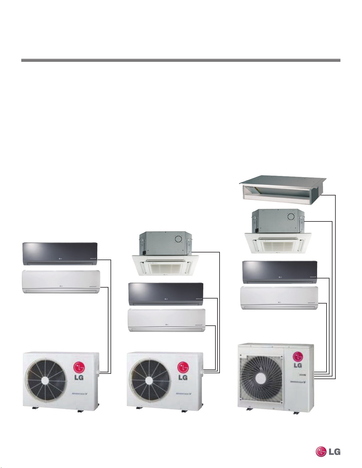
Figure 1: Dual-Zone Multi F Heat Pump
Inverter System — Mix and match for
9,000-24,000 Btu/h.
16 | MULTI F OUTDOOR UNIT
©LG Electronics U.S.A., Inc., Englewood Cliffs, NJ. All rights reserved. “LG” is a registered trademark of LG Corp.
Figure 2: Tri-Zone Multi F Heat Pump
Inverter System — Mix and match for
12,000-33,000 Btu/h.
Due to our policy of continuous product innovation, some specications may change without notication.
Figure 3: Quad-Zone Multi F Heat Pump
Inverter System — Mix and match for
18,000-48,000 Btu/h.
MULTI
F
MAX
MULTI
F
MULTI F SYSTEMS
Mechanical Specications
Multi F Heat Pump Condensing Units
General
A Multi F multi-zone system is comprised of one heat pump outdoor
unit connected to two, three, or four indoor units using a shared
refrigerant piping circuit between the outdoor unit and each indoor
unit, and includes integrated controls supplied by LG. The outdoor
unit is internally assembled, wired, and piped from the factory; all LG
components are manufactured in a facility registered to ISO 9001 and
ISO 14001, set by the International Organization for Standardization
(ISO). The LG Multi F multi zone heat pump system components
comply with Underwriters Laboratories (UL) 1995 Heating and Cooling Equipment Standard for Safety, and bear the Electrical Testing
Laboratories (ETL) mark. The units are certied to AHRI 210 / 240.
Temperature Ranges
The heat pump outdoor units are capable of operating in cooling
mode from 14°F to +118°F ambient dry bulb (installing an optional
Low Ambient Wind Baffle Kit will allow operation down to -4°F in
cooling mode for all Multi F systems). The heat pump outdoor units
are capable of operating in heating mode from -4°F to +64°F ambient wet bulb without additional low ambient controls.
Frame
The Multi F condensing unit case is constructed from pre-coated
metal that has been tested in accordance with ASTM B-117 salt
spray procedure for a minimum of 1,000 hours. Case has a removable front panel to allow access to major components and control
devices, and legs to secure the unit during installation.
Refrigerant System
Multi F systems have a shared refrigerant circuit field piped to
multiple (ducted, non-ducted or mixed) indoor units to effectively and
efficiently control the heating or cooling operation of the multi zone
system. All refrigerant lines from the outdoor unit to the indoor units
are field-installed and must be insulated separately.
All Multi F systems use R410A refrigerant. The outdoor units are
equipped with a refrigerant strainer, check valves, oil separator,
accumulator, four-way reversing valve, electronic expansion valve(s)
(EEV), high side and low side refrigerant charging ports, and a
service port. Each outdoor unit also includes sensors for suction
temperature, discharge temperature, high-pressure, low-pressure,
heat exchanger temperature, and outdoor temperature conditions.
Figure 4: Multi F LMU18CHV and
LMU24CHV Outdoor Units.
includes Teflon™ coated bearings. The inverter motor is capable
of providing a modulation range of 20Hz to 100Hz with control in
1Hz increments. The compressor is protected with phase-reversal
protection, uses a factory-charge of Polyvinyl Ether (PVE) oil, and is
mounted to avoid the transmission of vibration.
Figure 5: Multi F LMU36CHV
Outdoor Unit.
Fan and Motors
Each outdoor unit includes one direct drive variable speed propeller
fan with Brushless Digitally Controlled (BLDC) motor with a horizontal air discharge. Fan blades are statically and dynamically balanced
propeller fans made of durable Acrylonitrile Butadiene Styrene (ABS)
plastic, and include a raised fan guard to limit contact with moving
parts. The motors have inherent overload protection, permanently
lubricated bearings, and a maximum speed up to 950 rpm. All Multi F
outdoor units have a horizontal discharge airflow.
Outdoor Unit Coil
The outdoor unit coils are factory-built of aluminum fins mechanically bonded on copper tubing. Coils have a minimum of two rows, a
minimum of 14 fins per inch, and have been factory pressure-tested.
Coil fins also have a factory applied corrosion-resistant GoldFin™
material with hydrophilic coating that has been tested in accordance
with ASTM B-117 salt spray test procedure for a minimum of 1,000
hours.
Electrical
All Multi F outdoor units shall have 208/230V, 1 phase, 60Hz electrical power capable of operating within ±10% of the rated voltage.
Multi F Outdoor Unit Data
Refrigeration Oil Control
The outdoor units have an oil separator to separate oil mixed with
the refrigerant gas during compression and return oil to the compressor. The outdoor units also have an oil injection mechanism to
ensure a consistent film of oil on all moving compressor parts at low
speed.
Compressor
Multi F condensing units are equipped with one hermetically sealed,
digitally controlled, inverter driven twin-rotary compressor that
Controls
Factory installed microprocessor controls in the outdoor unit and
indoor units shall perform functions to efficiently operate the multizone system. System wiring must be installed in a tree configuration from outdoor unit to indoor units through four conductor power/
transmission cable. The system is capable of performing continuous
operation, even when power is turned off to an individual indoor unit.
Due to our policy of continuous product innovation, some specications may change without notication.
©LG Electronics U.S.A., Inc., Englewood Cliffs, NJ. All rights reserved. “LG” is a registered trademark of LG Corp.
MULTI F OUTDOOR UNIT | 17
MULTI
F
MAX
MULTI
F
MULTI F OUTDOOR UNIT
General Data
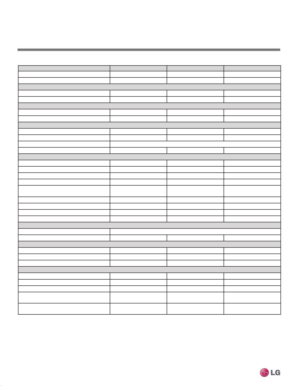
Table 12: Multi F Outdoor Unit Specications.
Model Number
Rated Cooling Capacity (Btu/h)
Rated Heating Capacity (Btu/h)
1
1
Operating Range
Cooling (°F DB)
Heating (°F WB)
Compressor
Inverter Quantity
Oil/Type
Fan (Side Discharge)
Type
Motor Output (W) x Qty.
Motor/Drive
Maximum Air Volume (CFM)
Unit Data
Refrigerant Type
Refrigerant Control/Location
Min. Number Indoor Units/System
Max. Number Indoor Units/System
2
2
Maximum Allowable Total Indoor Unit
Connected Capacity (Btu/h)
Sound Pressure (Cooling / Heating) dB(A)
3
Net Unit Weight (lbs.)
Shipping Weight (lbs.)
Power Wiring4 (No. x AWG)
Heat Exchanger
Material and Fin Coating
Rows/Columns/Fins per inch x Qty.
Piping
Liquid Line Connection (in., OD) x Qty.
Vapor Line Connection (in., OD) x Qty.
Factory Charge lbs. of R410A
Piping Lengths
Maximum Total Piping (ft.)
5
Maximum Outdoor Unit to Indoor Unit Piping (ft)
Piping Length (No Additional Refrigerant [ft])
Multi F and Multi F MAX Heat Pump System Engineering Manual
Maximum Elevation between Outdoor Unit and
Indoor Unit (ft.)
Maximum Elevation between Indoor Unit and
Indoor Unit (ft.)
1
Rated capacity applied with non-ducted indoor units, and is rated 0 ft. above sea level with 25 ft.
of refrigerant line per indoor unit and a 0 ft. level difference between outdoor and indoor units. All
capacities are net with a combination ratio between 95 – 105%.
Rated cooling capacity obtained with air entering the indoor unit at 80ºF dry bulb (DB) and 67ºF wet
bulb (WB) and outdoor ambient conditions of 95ºF dry bulb (DB) and 75ºF wet bulb (WB).
Rated heating capacity obtained with air entering the indoor unit at 70ºF dry bulb (DB) and 60ºF wet
bulb (WB) and outdoor ambient conditions of 47ºF dry bulb (DB) and 43ºF wet bulb (WB).
2
At least two indoor units should be connected. For allocated capacity information, see the combination
tables on pages 23 to 38.
LMU18CHV LMU24CHV LMU36CHV
17,000 20,000 32,000
22,000 24,000 36,000
146 - 118 146 - 118 146 - 118
-4 - 64 -4 - 64 -4 - 64
Twin Rotary x 1 Twin Rotary x 1 Twin Rotary x 1
FVC68D FVC68D FVC68D
Propeller Propeller Propeller
85.4 x 1 85.4 x 1 124.2 x 1
Brushless Digitally Controlled / Direct
1,766 1,766 2,119
R410A R410A R410A
EEV/Outdoor Unit EEV/Outdoor Unit EEV/Outdoor Unit
2 2 2
2 3 4
24,000 33,000 48,000
49 / 52 49 / 52 52 / 55
100 100 137
108 108 148
3C x 14 3C x 12 3C x 12
Copper Tube/Aluminum Fin and GoldFin™/Hydrophilic
(2 x 28 x 14) x 1 (2 x 28 x 14) x 1 (2 x 38 x 14) x 1
1/4 x 2 1/4 x 3 1/4 x 4
3/8 x 2 3/8 x 3 3/8 x 4
3.96 3.96 6.18
164.0 246.1 246.1
82.0 82.0 82.0
49.2 73.8 98.4
49.2 49.2 49.2
24.6 24.6 24.6
3
Sound pressure levels are tested in an anechoic chamber under ISO Standard 3745 and are the
same in both cooling and heating mode. These values can increase due to ambient conditions during
operation.
4
All power wiring minimum 3-conductor, stranded, shielded, and must comply with applicable local and
national codes. For detailed electrical information, please refer to electric characteristics on page 279.
5
Piping lengths are equivalent.
6
Installation of an optional Low Ambient Wind Baffle Kit will allow operation down to -4°F in cooling
mode.
18 | MULTI F OUTDOOR UNIT
Due to our policy of continuous product innovation, some specications may change without notication.
©LG Electronics U.S.A., Inc., Englewood Cliffs, NJ. All rights reserved. “LG” is a registered trademark of LG Corp.
MULTI
F
MAX
MULTI
F
MULTI F OUTDOOR UNIT
General Data
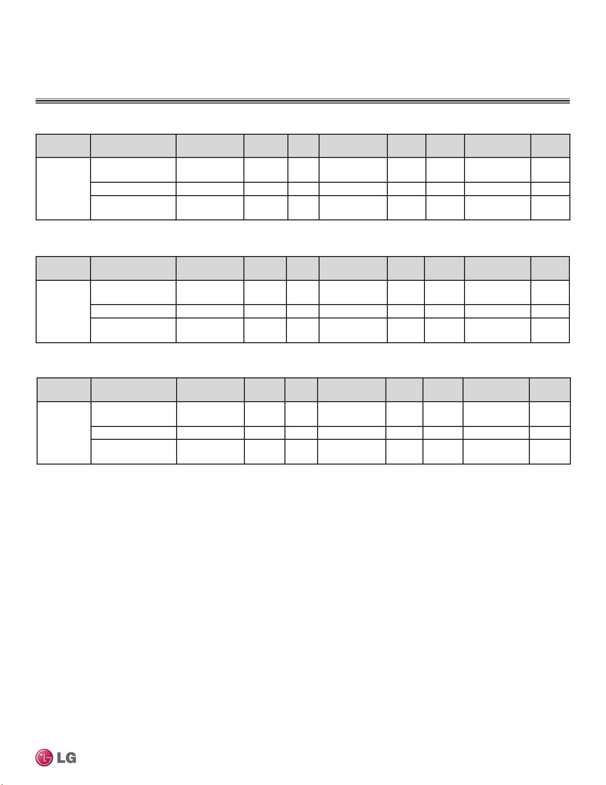
Table 13: LMU18CHV Efciency Ratings.
System Combined With
Non-Ducted
Indoor Units
LMU18CHV
Table 14: LMU24CHV Efciency Ratings.
System Combined With
LMU24CHV
Table 15: LMU36CHV Efciency Ratings.
System Combined With
LMU36CHV
1
Rated capacity is rated 0 ft. above sea level with 25 ft. of refrigerant line per indoor unit and a 0 ft. level difference between outdoor and indoor units.
All capacities are net with a combination ratio between 95 – 105%.
Rated cooling capacity rating obtained with air entering the indoor unit at 80ºF dry bulb (DB) and 67ºF wet bulb (WB) and outdoor ambient conditions
of 95ºF dry bulb (DB) and 75ºF wet bulb (WB).
Rated heating capacity rating obtained with air entering the indoor unit at 70ºF dry bulb (DB) and 60ºF wet bulb (WB) and outdoor ambient conditions
of 47ºF dry bulb (DB) and 43ºF wet bulb (WB).
2
Rated capacity is certied under AHRI Standard 210 / 240. EER, IEER, COP, and HSPF are subject to change. See www.ahrinet.org for the latest
values.
Ducted Indoor Units 14,000 10.7 17.2 19,800 2.9 9.7 13,000 2.4
Mixed Non-Ducted and
Ducted Indoor Units
Non-Ducted
Indoor Units
Ducted Indoor Units 17,800 11.5 17.5 22,500 3.4 9.8 14,000 2.5
Mixed Non-Ducted and
Ducted Indoor Units
Non-Ducted
Indoor Units
Ducted Indoor Units 28,000 11.0 18.2 34,000 3.5 9.7 19,500 2.4
Mixed Non-Ducted and
Ducted Indoor Units
1,2
Rated Cooling
Capacity (Btu/h)
17,000 13.0 22.0 22,000 3.2 9.7 13,500 2.4
15,500 11.8 19.6 20,900 3.0 9.7 13,250 2.4
1,2,
Rated Cooling
Capacity (Btu/h)
20,000 13.5 21.7 24,000 3.9 10.6 14,500 2.7
18,900 12.5 19.6 23,250 3.7 10.2 14,250 2.6
1,2
Rated Cooling
Capacity (Btu/h)
32,000 13.0 22.0 36,000 3.9 10.0 20,000 2.6
30,000 12.0 20.1 35,000 3.7 9.9 19,750 2.5
EER
(95°F)
EER
(95°F)
EER
(95°F)
SEER
SEER
SEER
Rated Heating
Capacity (Btu/h)
Rated Heating
Capacity (Btu/h)
Rated Heating
Capacity (Btu/h)
COP
(47°F)
COP
(47°F)
COP
(47°F)
HSPF
HSPF
HSPF
Low Heating
Capacity (Btu/h)
Low Heating
Capacity (Btu/h)
Low Heating
Capacity (Btu/h)
COP
(17°F)
COP
(17°F)
COP
(17°F)
Multi F Outdoor Unit Data
Due to our policy of continuous product innovation, some specications may change without notication.
©LG Electronics U.S.A., Inc., Englewood Cliffs, NJ. All rights reserved. “LG” is a registered trademark of LG Corp.
MULTI F OUTDOOR UNIT | 19

MULTI
F
MAX
MULTI
F
MULTI F OUTDOOR UNIT
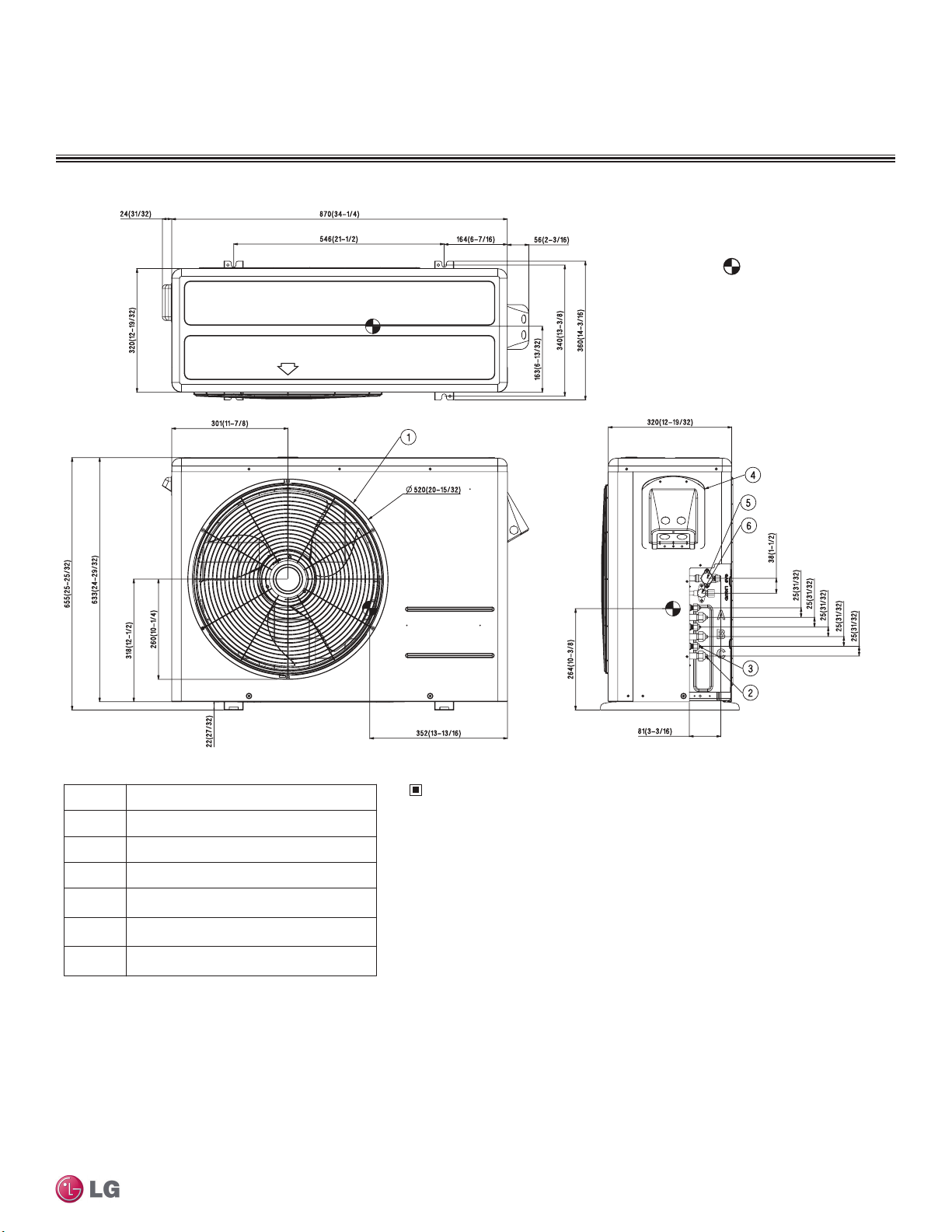
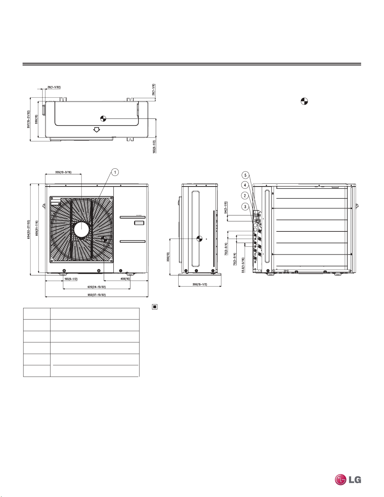
1. Unit should be installed in compliance with the installation manual in
the product box.
2. Unit should be grounded in accordance with the local regulations or
applicable national codes.
3. All electrical components and materials to be supplied on the site
must comply with the local regulations or international codes.
4. Electrical characteristics chapter should be considered for electrical
work and design. Especially the capacity of power cable and circuit
breaker for outdoor unit should be more than that of electrical
characteristics chapter.
Note
Gas pipe connection
Part Name
Air discharge grille
Liquid pipe connection
Power & transmission connection
No.
2
4
Main service valve(Gas)
Main service valve(Liquid)
5
6
3
1
[Unit : mm(inch)]
Gravity point
Dimensions
Figure 6: LMU18CHV External Dimensions.
Multi F and Multi F MAX Heat Pump System Engineering Manual
20 | MULTI F OUTDOOR UNIT
Due to our policy of continuous product innovation, some specications may change without notication.
©LG Electronics U.S.A., Inc., Englewood Cliffs, NJ. All rights reserved. “LG” is a registered trademark of LG Corp.
MULTI
F
MAX
MULTI
F
Figure 7: LMU24CHV External Dimensions.
MULTI F OUTDOOR UNIT
Dimensions
[Unit : mm(inch)]
Gravity point
Multi F Outdoor Unit Data
No.
1
2
3
4
5
6
Part Name
Air discharge grille
Gas pipe connection
Liquid pipe connection
Power & transmission connection
Main service valve(Gas)
Main service valve(Liquid)
Due to our policy of continuous product innovation, some specications may change without notication.
©LG Electronics U.S.A., Inc., Englewood Cliffs, NJ. All rights reserved. “LG” is a registered trademark of LG Corp.
Note
1. Unit should be installed in compliance with the installation manual in
the product box.
2. Unit should be grounded in accordance with the local regulations or
applicable national codes.
3. All electrical components and materials to be supplied on the site
must comply with the local regulations or international codes.
4. Electrical characteristics chapter should be considered for electrical
work and design. Especially the capacity of power cable and circuit
breaker for outdoor unit should be more than that of electrical
characteristics chapter.
MULTI F OUTDOOR UNIT | 21
MULTI
F
MAX
MULTI
F
MULTI F OUTDOOR UNIT
1. Unit should be installed in compliance with the installation manual in
the product box.
2. Unit should be grounded in accordance with the local regulations or
applicable national codes.
3. All electrical components and materials to be supplied on the site
must comply with the local regulations or international codes.
4. Electrical characteristics chapter should be considered for electrical
work and design. Especially the capacity of power cable and circuit
breaker for outdoor unit should be more than that of electrical
characteristics chapter.
Note
Gas pipe connection
Part Name
Air discharge grille
Liquid pipe connection
Main service valve(Gas)
Main service valve(Liquid)
5
No.
2
4
3
1
[Unit : mm(inch)]
Gravity point
Dimensions
Figure 8: LMU36CHV External Dimensions.
Multi F and Multi F MAX Heat Pump System Engineering Manual
22 | MULTI F OUTDOOR UNIT
Due to our policy of continuous product innovation, some specications may change without notication.
©LG Electronics U.S.A., Inc., Englewood Cliffs, NJ. All rights reserved. “LG” is a registered trademark of LG Corp.

MULTI
F
MAX
MULTI
F
PERFORMANCE DATA
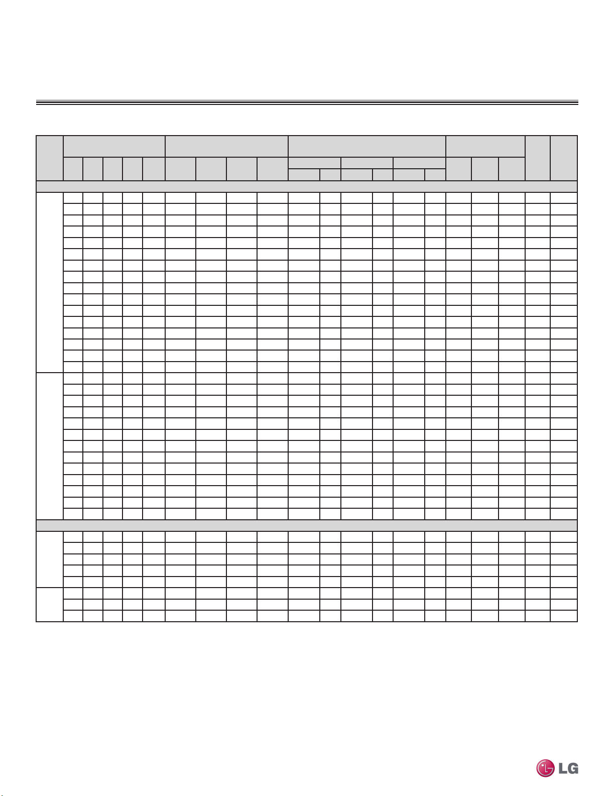
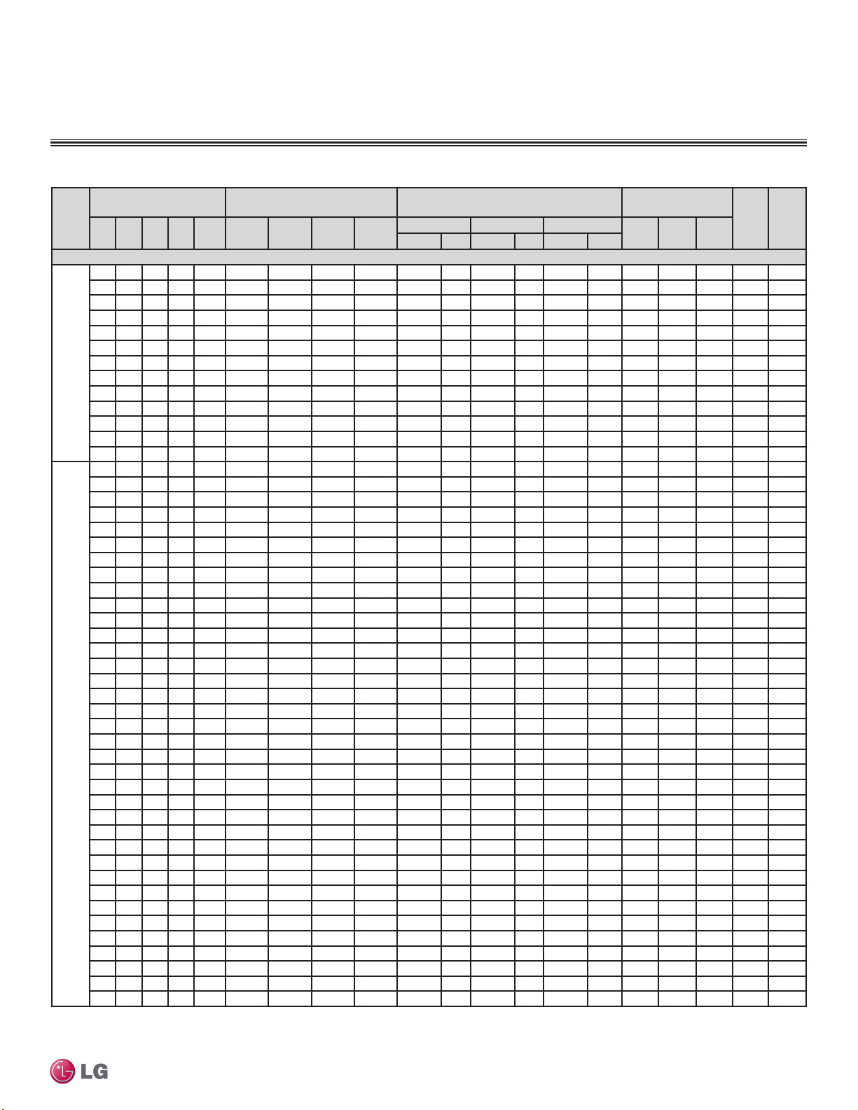
Rated Cooling Combination Tables
Table 16: LMU18CHV with Non-Ducted, Ducted, and Mixed Indoor Units — Rated Cooling Combination Table.
No. of
Indoor
Units
Non-Ducted Indoor Units
Ducted Indoor Units
Mixed Indoor Units
1
Capacity as rated: 0 ft. above sea level with 25 ft. of refrigerant piping.
0 ft. level difference between outdoor and indoor units.
2
Cooling capacity rating obtained with air entering the indoor unit at 80ºF dry bulb (DB) and 67ºF wet
bulb (WB), and outdoor ambient conditions of 95ºF dry bulb (DB) and 75ºF wet bulb (WB).
Indoor Unit Combination
(kBtu/h)
IDU 1IDU 2IDU 3IDU
7 7 - - 14 7,000 7,000 - - 8,400 2.46 14,000 4.10 16,800 4.92 826 1,180 1,652 11.9 20.1
7 9 - - 16 7,000 9,000 - - 9,600 2.81 16,000 4.69 19,000 5.57 868 1,240 1,736 12.9 21.9
9 9 - - 18 8,500 8,500 - - 10,200 3.16 17,000 4.98 19,000 5.57 917 1,310 1,834 13.0 22.0
Two
Units
Two
Units
Two
Units
7 12 - - 19 6,263 10,737 - - 10,200 2.99 17,000 4.98 19,000 5.57 917 1,310 1,834 13.0 22.0
9 12 - - 21 7,286 9,714 - - 10,200 3.16 17,000 4.98 19,000 5.57 917 1,310 1,834 13.0 22.0
7 15 - - 22 5,409 11,591 - - 10,200 2.99 17,000 4.98 19,000 5.57 917 1,310 1,834 13.0 22.0
9 15 - - 24 6,375 10,625 - - 10,200 2.99 17,000 4.98 19,000 5.57 917 1,310 1,834 13.0 22.0
12 12 - - 24 8,500 8,500 - - 10,200 3.16 17,000 4.98 19,000 5.57 917 1,310 1,834 13.0 22.0
9 9 - - 18 7,000 7,000 - - 8,400 3.16 14,000 4.10 19,000 5.57 916 1,308 1,831 10.7 17.2
9 12 - - 21 6,000 8,000 - - 8,400 3.16 14,000 4.10 19,000 5.57 916 1,308 1,831 10.7 17.2
12 12 - - 24 7,000 7,000 - - 8,400 3.16 14,000 4.10 19,000 5.57 916 1,308 1,831 10.7 17.2
7 9 - - 16 6,382 8,206 - - 8,753 2.57 14,588 4.28 19,000 5.57 867 1,239 1,735 11.8 19.5
9 9 - - 18 7,750 7,750 - - 9,300 3.16 15,500 4.54 19,000 5.57 916 1,309 1,833 11.8 19.6
7 12 - - 19 5,711 9,789 - - 9,300 2.73 15,500 4.54 19,000 5.57 916 1,309 1,833 11.8 19.6
9 12 - - 21 6,643 8,857 - - 9,300 3.16 15,500 4.54 19,000 5.57 916 1,309 1,833 11.8 19.6
9 15 - - 24 5,813 9,688 - - 9,300 2.73 15,500 4.54 19,000 5.57 916 1,309 1,833 11.8 19.6
12 12 - - 24 7,750 7,750 - - 9,300 3.16 15,500 4.54 19,000 5.57 916 1,309 1,833 11.8 19.6
Total
4
Room Capacity Total Capacity Input (W)
Unit 1
(Btu/h)
Unit 2
(Btu/h)
Unit 3
(Btu/h)
Unit 4
(Btu/h)
Minimum Rated Maximum
Btu/h kW Btu/h kW Btu/h kW
3
Wiring cable size must comply with the applicable local and national codes.
4
The specification may be subject to change without prior notice for purpose of improvement.
5
At least two indoor units should be connected.
EER SEER
Min. Rated Max.
Multi F Outdoor Unit Data
Due to our policy of continuous product innovation, some specications may change without notication.
©LG Electronics U.S.A., Inc., Englewood Cliffs, NJ. All rights reserved. “LG” is a registered trademark of LG Corp.
MULTI F OUTDOOR UNIT | 23
MULTI
F
MAX
MULTI
F
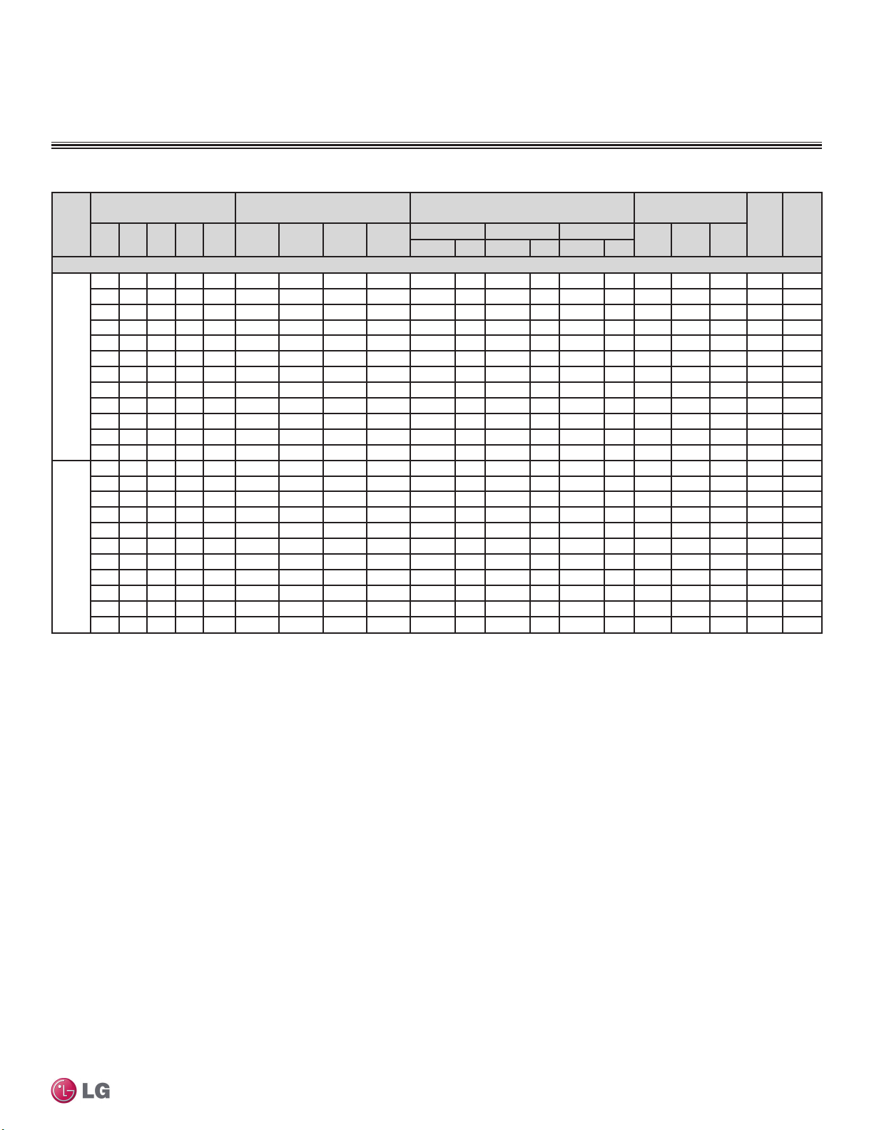
PERFORMANCE DATA
Rated Cooling Combination Tables
Table 17: LMU24CHV with Non-Ducted and Ducted Indoor Units — Rated Cooling Combination Table.
No. of
Indoor
Non-Ducted Indoor Units
Three
Ducted Indoor Units
Multi F and Multi F MAX Heat Pump System Engineering Manual
Three
1
Capacity as rated: 0 ft. above sea level with 25 ft. of refrigerant piping.
0 ft. level difference between outdoor and indoor units.
2
Cooling capacity rating obtained with air entering the indoor unit at 80ºF dry bulb (DB) and 67ºF wet
bulb (WB), and outdoor ambient conditions of 95ºF dry bulb (DB) and 75ºF wet bulb (WB).
Indoor Unit Combination
(kBtu/h)
IDU 1IDU 2IDU 3IDU
Units
7 7 - - 14 7,000 7,000 - - 8,400 2.46 14,000 4.10 16,800 4.92 798 1,140 1,596 12.3 19.7
7 9 - - 16 7,000 9,000 - - 9,600 2.81 16,000 4.69 19,200 5.63 903 1,290 1,806 12.4 19.9
9 9 - - 18 9,000 9,000 - - 10,800 3.17 18,000 5.28 21,600 6.33 1,008 1,440 2,016 12.5 20.1
7 12 - - 19 7,000 12,000 - - 11,400 3.34 19,000 5.57 22,800 6.68 1,057 1,510 2,114 12.6 20.2
9 12 - - 21 8,571 11,429 - - 12,000 3.52 20,000 5.86 24,000 7.03 1,106 1,580 2,212 12.7 20.3
7 15 - - 22 6,364 13,636 - - 12,000 3.52 20,000 5.86 24,000 7.03 1,106 1,580 2,212 12.7 20.3
9 15 - - 24 7,500 12,500 - - 12,000 3.52 20,000 5.86 24,000 7.03 1,106 1,580 2,212 12.7 20.3
Two
12 12 - - 24 10,000 10,000 - - 12,000 3.52 20,000 5.86 24,000 7.03 1,106 1,580 2,212 12.7 20.3
7 18 - - 25 5,600 14,400 - - 12,000 3.52 20,000 5.86 24,000 7.03 1,106 1,580 2,212 12.7 20.3
Units
9 18 - - 27 6,667 13,333 - - 12,000 3.52 20,000 5.86 24,000 7.03 1,106 1,580 2,212 12.7 20.3
12 15 - - 27 8,889 11,111 - - 12,000 3.52 20,000 5.86 24,000 7.03 1,106 1,580 2,212 12.7 20.3
12 18 - - 30 8,000 12,000 - - 12,000 3.52 20,000 5.86 24,000 7.03 1,106 1,580 2,212 12.7 20.3
15 15 - - 30 10,000 10,000 - - 12,000 3.52 20,000 5.86 24,000 7.03 1,106 1,580 2,212 12.7 20.3
7 24 - - 31 4,516 15,484 - - 12,000 3.52 20,000 5.86 24,000 7.03 1,106 1,580 2,212 12.7 20.3
9 24 - - 33 5,455 14,545 - - 12,000 3.52 20,000 5.86 24,000 7.03 1,106 1,580 2,212 12.7 20.3
15 18 - - 33 9,091 10,909 - - 12,000 3.52 20,000 5.86 24,000 7.03 1,106 1,580 2,212 12.7 20.3
7 7 7 - 21 6,667 6,667 6,667 - 12,000 3.52 20,000 5.86 25,000 7.33 1,037 1,481 2,073 13.5 21.7
7 7 9 23 6,087 6,087 7,826 - 12,000 3.52 20,000 5.86 25,000 7.33 1,037 1,481
7 9 9 25 5,600 7,200 7,200 - 12,000 3.52 20,000 5.86 25,000 7.33 1,037 1,481 2,073 13.5 21.7
7 7 12 26 5,385 5,385 9,231 - 12,000 3.52 20,000 5.86 25,000 7.33 1,037 1,481 2,073 13.5 21.7
9 9 9 - 27 6,667 6,667 6,667 - 12,000 3.52 20,000 5.86 25,000 7.33 1,037 1,481 2,073 13.5 21.7
7 9 12 28 5,000 6,429 8,571 - 12,000 3.52 20,000 5.86 25,000 7.33 1,037 1,481 2,073 13.5 21.7
Units
7 7 15 29 4,828 4,828 10,345 - 12,000 3.52 20,000 5.86 25,000 7.33 1,037 1,481 2,073 13.5 21.7
9 9 12 - 30 6,000 6,000 8,000 - 12,000 3.52 20,000 5.86 25,000 7.33 1,037 1,481 2,073 13.5 21.7
7 9 15 31 4,516 5,806 9,677 - 12,000 3.52 20,000 5.86 25,000 7.33 1,037 1,481 2,073 13.5 21.7
7 12 12 31 4,516 7,742 7,742 - 12,000 3.52 20,000 5.86 25,000 7.33 1,037 1,481 2,073 13.5 21.7
7 7 18 32 4,375 4,375 11,250 - 12,000 3.52 20,000 5.86 25,000 7.33 1,037 1,481 2,073 13.5 21.7
9 9 15 33 5,455 5,455 9,091 - 12,000 3.52 20,000 5.86 25,000 7.33 1,037 1,481 2,073 13.5 21.7
9 12 12 - 33 5,455 7,273 7,273 - 12,000 3.52 20,000 5.86 25,000 7.33 1,037 1,481 2,073 13.5 21.7
9 9 - - 18 8,010 8,010 - - 9,612 2.82 16,020 4.70 19,224 5.63 1,054 1,505 2,107 10.6 16.2
9 12 - - 21 7,629 10,171 - - 10,680 3.13 17,800 5.22 21,360 6.26 1,156 1,651 2,312 10.8 16.4
Two
12 12 - - 24 8,900 8,900 - - 10,680 3.13 17,800 5.22 21,360 6.26 1,156 1,651 2,312 10.8 16.4
Units
9 18 - - 27 5,933 11,867 - - 10,680 3.13 17,800 5.22 21,360 6.26 1,156 1,651 2,312 10.8 16.4
12 18 - - 30 7,120 10,680 - - 10,680 3.13 17,800 5.22 21,360 6.26 1,156 1,651 2,312 10.8 16.4
9 9 9 - 27 5,933 5,933 5,933 - 10,680 3.13 17,800 5.22 22,250 6.52 1,084 1,548 2,167 11.5 17.5
9 9 12 - 30 5,340 5,340 7,120 - 10,680 3.13 17,800 5.22 22,250 6.52 1,084 1,548 2,167 11.5 17.5
Units
9 12 12 - 33 4,855 6,473 6,473 - 10,680 3.13 17,800 5.22 22,250 6.52 1,084 1,548 2,167 11.5 17.5
Total
4
(Btu/h)
Room Capacity Total Capacity Input (W)
Unit 1
Unit 2
(Btu/h)
Unit 3
(Btu/h)
Unit 4
(Btu/h)
Minimum Rated Maximum
Btu/h kW Btu/h kW Btu/h kW
3
Wiring cable size must comply with the applicable local and national codes.
4
The specification may be subject to change without prior notice for purpose of improvement.
*
At least two indoor units should be connected.
EER SEER
Min. Rated Max.
2,073 13.5 21.7
24 | MULTI F OUTDOOR UNIT
Due to our policy of continuous product innovation, some specications may change without notication.
©LG Electronics U.S.A., Inc., Englewood Cliffs, NJ. All rights reserved. “LG” is a registered trademark of LG Corp.
MULTI
F
MAX
MULTI
F
Table 18: LMU24CHV with Mixed Indoor Units — Rated Cooling Combination Table.
No. of
Indoor
Mixed Indoor Units
Three
1
Capacity as rated: 0 ft. above sea level with 25 ft. of refrigerant piping.
0 ft. level difference between outdoor and indoor units.
2
Cooling capacity rating obtained with air entering the indoor unit at 80ºF dry bulb (DB) and 67ºF wet
bulb (WB), and outdoor ambient conditions of 95ºF dry bulb (DB) and 75ºF wet bulb (WB).
Indoor Unit Combination
(kBtu/h)
IDU 1IDU 2IDU 3IDU
Units
7 9 - - 16 6,615 8,505 - - 9,072 2.66 15,120 4.43 18,144 5.32 923 1,319 1,847 11.5 18.0
9 9 - - 18 8,505 8,505 - - 10,206 2.99 17,010 4.99 20,412 5.98 1,031 1,473 2,062 11.6 18.1
7 12 - - 19 6,615 11,340 - - 10,773 3.16 17,955 5.26 21,546 6.31 1,081 1,544 2,162 11.6 18.3
9 12 - - 21 8,100 10,800 - - 11,340 3.32 18,900 5.54 22,680 6.65 1,131 1,616 2,262 11.7 18.4
9 15 - - 24 7,088 11,813 - - 11,340 3.32 18,900 5.54 22,680 6.65 1,131 1,616 2,262 11.7 18.4
Two
12 12 - - 24 9,450 9,450 - - 11,340 3.32 18,900 5.54 22,680 6.65 1,131 1,616 2,262 11.7 18.4
Units
Units
7 18 - - 25 5,292 13,608 - - 11,340 3.32 18,900 5.54 22,680 6.65 1,131 1,616 2,262 11.7 18.4
9 18 - - 27 6,300 12,600 - - 11,340 3.32 18,900 5.54 22,680 6.65 1,131 1,616 2,262 11.7 18.4
12 15 - - 27 8,400 10,500 - - 11,340 3.32 18,900 5.54 22,680 6.65 1,131 1,616 2,262 11.7 18.4
12 18 - - 30 7,560 11,340 - - 11,340 3.32 18,900 5.54 22,680 6.65 1,131 1,616 2,262 11.7 18.4
15 18 - - 33 8,591 10,309 - - 11,340 3.32 18,900 5.54 22,680 6.65 1,131 1,616 2,262 11.7 18.4
9 24* - - 33 5,155 13,745 - - 11,340 3.32 18,900 5.54 22,680 6.65 1,131 1,616 2,262 11.7 18.4
7 7 9 - 23 5,752 5,752 7,396 - 11,340 3.32 18,900 5.54 23,625 6.92 1,060 1,515 2,120 12.5 19.6
7 9 9 - 25 5,292 6,804 6,804 - 11,340 3.32 18,900 5.54 23,625 6.92 1,060 1,515 2,120 12.5 19.6
7 7 12 - 26 5,088 5,088 8,723 - 11,340 3.32 18,900 5.54 23,625 6.92 1,060 1,515 2,120 12.5 19.6
9 9 9 - 27 6,300 6,300 6,300 - 11,340 3.32 18,900 5.54 23,625 6.92 1,060 1,515 2,120 12.5 19.6
7 9 12 - 28 4,725 6,075 8,100 - 11,340 3.32 18,900 5.54 23,625 6.92 1,060 1,515 2,120 12.5 19.6
9 9 12 - 30 5,670 5,670 7,560 - 11,340 3.32 18,900 5.54 23,625 6.92 1,060
7 9 15 - 31 4,268 5,487 9,145 - 11,340 3.32 18,900 5.54 23,625 6.92 1,060 1,515 2,120 12.5 19.6
7 12 12 - 31 4,268 7,316 7,316 - 11,340 3.32 18,900 5.54 23,625 6.92 1,060 1,515 2,120 12.5 19.6
7 7 18 - 32 4,134 4,134 10,631 - 11,340 3.32 18,900 5.54 23,625 6.92 1,060 1,515 2,120 12.5 19.6
9 9 15 - 33 5,155 5,155 8,591 - 11,340 3.32 18,900 5.54 23,625 6.92 1,060 1,515 2,120 12.5 19.6
9 12 12 - 33 5,155 6,873 6,873 - 11,340 3.32 18,900 5.54 23,625 6.92 1,060 1,515 2,120 12.5 19.6
Total
4
(Btu/h)
Room Capacity Total Capacity Input (W)
Unit 1
Unit 2
(Btu/h)
Unit 3
(Btu/h)
Unit 4
(Btu/h)
Minimum Rated Maximum
Btu/h kW Btu/h kW Btu/h kW
3
Wiring cable size must comply with the applicable local and national codes.
4
The specification may be subject to change without prior notice for purpose of improvement.
5
At least two indoor units should be connected.
*The indoor unit must be non-ducted type.
PERFORMANCE DATA
Rated Cooling Combination Tables
EER SEER
Min. Rated Max.
Multi F Outdoor Unit Data
1,515 2,120 12.5 19.6
Due to our policy of continuous product innovation, some specications may change without notication.
©LG Electronics U.S.A., Inc., Englewood Cliffs, NJ. All rights reserved. “LG” is a registered trademark of LG Corp.
MULTI F OUTDOOR UNIT | 25
MULTI
F
MAX
MULTI
F
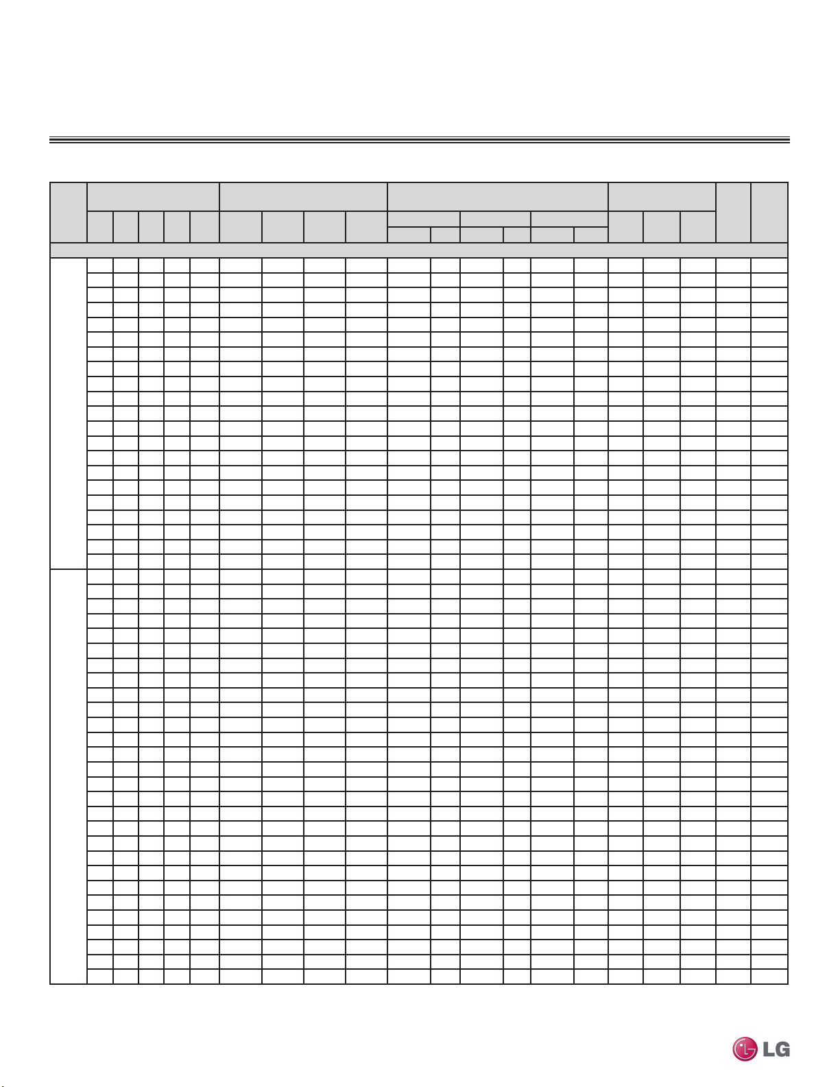
PERFORMANCE DATA
Rated Cooling Combination Tables
Table 19: LMU36CHV with Non-Ducted Indoor Units — Rated Cooling Combination Table.
Indoor Unit Combination
No. of
Indoor
IDU 1IDU 2IDU 3IDU
Units
(kBtu/h)
Total
4
(Btu/h)
Non-Ducted Indoor Units
7 7 - - 14 7,000 7,000 - - 8,400 2.46 14,000 4.10 15,540 4.55 952 1,360 1,904 10.3 17.4
7 9 - - 16 7,000 9,000 - - 9,600 2.81 16,000 4.69 17,760 5.21 1,071 1,530 2,142 10.5 17.7
9 9 - - 18 9,000 9,000 - - 10,800 3.17 18,000 5.28 19,980 5.86 1,204 1,720 2,408 10.5 17.7
7 12 - - 19 7,000 12,000 - - 11,400 3.34 19,000 5.57 21,090 6.18 1,260 1,800 2,520 10.6 17.9
9 12 - - 21 9,000 12,000 - - 12,600 3.69 21,000 6.15 23,310 6.83 1,379 1,970 2,758 10.7 18.0
7 15 - - 22 7,000 15,000 - - 13,200 3.87 22,000 6.45 24,420 7.16 1,428 2,040 2,856 10.8 18.2
9 15 - - 24 9,000 15,000 - - 14,400 4.22 24,000 7.03 26,640 7.81 1,526 2,180 3,052 11.0 18.6
12 12 - - 24 12,000 12,000 - - 14,400 4.22 24,000 7.03 26,640 7.81 1,526 2,180 3,052 11.0 18.6
7 18 - - 25 7,000 18,000 - - 15,000 4.40 25,000 7.33 27,750 8.13 1,582 2,260 3,164 11.1 18.7
9 18 - - 27 9,000 18,000 - - 16,200 4.75 27,000 7.91 29,970 8.78 1,694 2,420 3,388 11.2 18.9
Two
12 15 - - 27 12,000 15,000 - - 16,200 4.75 27,000 7.91 29,970 8.78 1,694 2,420 3,388 11.2 18.9
Units
12 18 - - 30 12,000 18,000 - - 18,000 5.28 30,000 8.79 33,300 9.76 1,841 2,630 3,682 11.4 19.3
15 15 - - 30 15,000 15,000 - - 18,000 5.28 30,000 8.79 33,300 9.76 1,841 2,630 3,682 11.4 19.3
7 24 - - 31 7,000 24,000 - - 18,600 5.45 31,000 9.09 34,410 10.08 1,883 2,690 3,766 11.5 19.5
9 24 - - 33 8,727 23,273 - - 19,200 5.63 32,000 9.38 35,520 10.41 1,932 2,760 3,864 11.6 19.6
15 18 - - 33 14,545 17,455 - - 19,200 5.63 32,000 9.38 35,520 10.41 1,932 2,760 3,864 11.6 19.6
18 18 - - 36 16,000 16,000 - - 19,200 5.63 32,000 9.38 35,520 10.41 1,932 2,760 3,864 11.6 19.6
12 24 - - 36 10,667 21,333 - - 19,200 5.63 32,000 9.38 35,520 10.41 1,932 2,760 3,864
15 24 - - 39 12,308 19,692 - - 19,200 5.63 32,000 9.38 35,520 10.41 1,932 2,760 3,864 11.6 19.6
18 24 - - 42 13,714 18,286 - - 19,200 5.63 32,000 9.38 35,520 10.41 1,932 2,760 3,864 11.6 19.6
24 24 - - 48 16,000 16,000 - - 19,200 5.63 32,000 9.38 35,520 10.41 1,932 2,760 3,864 11.6 19.6
7 7 7 - 21 7,000 7,000 7,000 - 12,600 3.69 21,000 6.15 24,150 7.08 1,337 1,910 2,674 11.0 18.6
7 7 9 - 23 7,000 7,000 9,000 - 13,800 4.04 23,000 6.74 26,450 7.75 1,442 2,060 2,884 11.2 18.9
7 9 9 - 25 7,000 9,000 9,000 - 15,000 4.40 25,000 7.33 28,750 8.43 1,554 2,220 3,108 11.3 19.1
7 7 12 - 26 7,000 7,000 12,000 - 15,600 4.57 26,000 7.62 29,900 8.76 1,582 2,260 3,164 11.5 19.5
9 9 9 - 27 9,000 9,000 9,000 - 16,200 4.75 27,000 7.91 31,050 9.10 1,610 2,300 3,220 11.7 19.9
7 9 12 - 28 7,000 9,000 12,000 - 16,800 4.92 28,000 8.21 32,200 9.44 1,645 2,350 3,290 11.9 20.2
7 7 15 - 29 7,000 7,000 15,000 - 17,400 5.10 29,000 8.50 33,350 9.77 1,680 2,400 3,360 12.1 20.4
9 9 12 - 30 9,000 9,000 12,000 - 18,000 5.28 30,000 8.79 34,500 10.11 1,722 2,460 3,444 12.2 20.6
7 9 15 - 31 7,000 9,000 15,000 - 18,600 5.45 31,000 9.09 35,650 10.45 1,764 2,520 3,528 12.3 20.8
7 12 12 - 31 7,000 12,000 12,000 - 18,600 5.45 31,000 9.09 35,650 10.45 1,764 2,520 3,528 12.3 20.8
7 7 18 - 32 7,000 7,000 18,000 - 19,200 5.63 32,000 9.38 36,800 10.79 1,806 2,580 3,612 12.4 21.0
9 9 15 - 33 8,727 8,727 14,545 - 19,200 5.63 32,000 9.38 36,800 10.79 1,806 2,580 3,612 12.4 21.0
9 12 12 - 33 8,727 11,636 11,636 - 19,200 5.63 32,000 9.38 36,800 10.79 1,806 2,580 3,612 12.4 21.0
Three
Multi F and Multi F MAX Heat Pump System Engineering Manual
1
Capacity as rated: 0 ft. above sea level with 25 ft. of refrigerant piping.
0 ft. level difference between outdoor and indoor units.
2
Cooling capacity rating obtained with air entering the indoor unit at 80ºF dry bulb (DB) and 67ºF wet
bulb (WB), and outdoor ambient conditions of 95ºF dry bulb (DB) and 75ºF wet bulb (WB).
26 | MULTI F OUTDOOR UNIT
7 9 18 - 34 6,588 8,471 16,941 - 19,200 5.63 32,000 9.38 36,800 10.79 1,806 2,580 3,612 12.4 21.0
7 12 15 - 34 6,588 11,294 14,118 - 19,200 5.63 32,000 9.38 36,800 10.79 1,806 2,580 3,612 12.4 21.0
Units
9 9 18 - 36 8,000 8,000 16,000 - 19,200 5.63 32,000 9.38 36,800 10.79 1,806 2,580 3,612 12.4 21.0
9 12 15 - 36 8,000 10,667 13,333 - 19,200 5.63 32,000 9.38 36,800 10.79 1,806
12 12 12 - 36 10,667 10,667 10,667 - 19,200 5.63 32,000 9.38 36,800 10.79 1,806 2,580 3,612 12.4 21.0
7 12 18 - 37 6,054 10,378 15,568 - 19,200 5.63 32,000 9.38 36,800 10.79 1,806 2,580 3,612 12.4 21.0
7 15 15 - 37 6,054 12,973 12,973 - 19,200 5.63 32,000 9.38 36,800 10.79 1,806 2,580 3,612 12.4 21.0
7 7 24 - 38 5,895 5,895 20,211 - 19,200 5.63 32,000 9.38 36,800 10.79 1,806 2,580 3,612 12.4 21.0
9 12 18 - 39 7,385 9,846 14,769 - 19,200 5.63 32,000 9.38 36,800 10.79 1,806 2,580 3,612 12.4 21.0
9 15 15 - 39 7,385 12,308 12,308 - 19,200 5.63 32,000 9.38 36,800 10.79 1,806 2,580 3,612 12.4 21.0
12 12 15 - 39 9,846 9,846 12,308 - 19,200 5.63 32,000 9.38 36,800 10.79 1,806 2,580 3,612 12.4 21.0
7 9 24 - 40 5,600 7,200 19,200 - 19,200 5.63 32,000 9.38 36,800 10.79 1,806 2,580 3,612 12.4 21.0
7 15 18 - 40 5,600 12,000 14,400 - 19,200 5.63 32,000 9.38 36,800 10.79 1,806 2,580 3,612 12.4 21.0
9 9 24 - 42 6,857 6,857 18,286 - 19,200 5.63 32,000 9.38 36,800 10.79 1,806 2,580 3,612 12.4 21.0
9 15 18 - 42 6,857 11,429 13,714 - 19,200 5.63 32,000 9.38 36,800 10.79 1,806 2,580 3,612 12.4 21.0
Room Capacity Total Capacity Input (W)
Unit 1
Unit 2
(Btu/h)
Due to our policy of continuous product innovation, some specications may change without notication.
©LG Electronics U.S.A., Inc., Englewood Cliffs, NJ. All rights reserved. “LG” is a registered trademark of LG Corp.
Unit 3
(Btu/h)
Unit 4
(Btu/h)
Minimum Rated Maximum
Btu/h kW Btu/h kW Btu/h kW
3
Wiring cable size must comply with the applicable local and national codes.
4
The specification may be subject to change without prior notice for purpose of improvement.
5
At least two indoor units should be connected.
EER SEER
Min. Rated Max.
11.6 19.6
2,580 3,612 12.4 21.0
MULTI
F
MAX
MULTI
F
Table 20: LMU36CHV with Non-Ducted Indoor Units — Rated Cooling Combination Table.
1
0 ft. level difference between outdoor and indoor units.
2
bulb (WB), and outdoor ambient conditions of 95ºF dry bulb (DB) and 75ºF wet bulb (WB).
Indoor Unit Combination
No. of
Indoor
IDU 1IDU 2IDU 3IDU
Units
(kBtu/h)
Total
4
(Btu/h)
Room Capacity Total Capacity Input (W)
Unit 1
Unit 2
(Btu/h)
Unit 3
(Btu/h)
Unit 4
(Btu/h)
Non-Ducted Indoor Units
12 12 18 - 42 9,143 9,143 13,714 - 19,200 5.63 32,000 9.38 36,800 10.79 1,806 2,580 3,612 12.4 21.0
12 15 15 - 42 9,143 11,429 11,429 - 19,200 5.63 32,000 9.38 36,800 10.79 1,806 2,580 3,612 12.4 21.0
7 12 24 - 43 5,209 8,930 17,860 - 19,200 5.63 32,000 9.38 36,800 10.79 1,806 2,580 3,612 12.4 21.0
7 18 18 - 43 5,209 13,395 13,395 - 19,200 5.63 32,000 9.38 36,800 10.79 1,806 2,580 3,612 12.4 21.0
9 12 24 - 45 6,400 8,533 17,067 - 19,200 5.63 32,000 9.38 36,800 10.79 1,806 2,580 3,612 12.4 21.0
Three
Capacity as rated: 0 ft. above sea level with 25 ft. of refrigerant piping.
Cooling capacity rating obtained with air entering the indoor unit at 80ºF dry bulb (DB) and 67ºF wet
9 18 18 - 45 6,400 12,800 12,800 - 19,200 5.63 32,000 9.38 36,800 10.79 1,806 2,580 3,612 12.4 21.0
12 15 18 - 45 8,533 10,667 12,800 - 19,200 5.63 32,000 9.38 36,800 10.79 1,806 2,580 3,612 12.4 21.0
Units
15 15 15 - 45 10,667 10,667 10,667 - 19,200 5.63 32,000 9.38 36,800 10.79 1,806 2,580 3,612 12.4 21.0
7 15 24 - 46 4,870 10,435 16,696 - 19,200 5.63 32,000 9.38 36,800 10.79 1,806 2,580 3,612 12.4 21.0
9 15 24 - 48 6,000 10,000 16,000 - 19,200 5.63 32,000 9.38 36,800 10.79 1,806 2,580 3,612 12.4 21.0
12 12 24 - 48 8,000 8,000 16,000 - 19,200 5.63 32,000 9.38 36,800 10.79 1,806 2,580 3,612 12.4 21.0
12 18 18 - 48 8,000 12,000 12,000 - 19,200 5.63 32,000 9.38 36,800 10.79 1,806 2,580 3,612 12.4 21.0
15 15 18 - 48 10,000 10,000 12,000 - 19,200 5.63 32,000 9.38 36,800 10.79 1,806 2,580 3,612 12.4 21.0
7 7 7 7 28 7,000 7,000 7,000 7,000 16,800 4.92 28,000 8.21 33,600 9.85 1,540 2,200 3,080 12.7 21.5
7 7 7 9 30 7,000 7,000 7,000 9,000 18,000 5.28 30,000 8.79 36,000 10.55 1,645 2,350 3,290 12.8 21.6
7 7 9 9 32 7,000 7,000 9,000 9,000 19,200 5.63 32,000 9.38 38,400 11.25 1,723 2,461 3,445 13.0 22.0
7 7 7 12 33 6,788 6,788 6,788 11,636 19,200 5.63 32,000 9.38 38,400 11.25 1,723 2,461 3,445 13.0 22.0
7 9 9 9 34 6,588 8,471 8,471 8,471 19,200 5.63 32,000 9.38 38,400 11.25 1,723
7 7 9 12 35 6,400 6,400 8,229 10,971 19,200 5.63 32,000 9.38 38,400 11.25 1,723 2,461 3,445 13.0 22.0
7 7 7 15 36 6,222 6,222 6,222 13,333 19,200 5.63 32,000 9.38 38,400 11.25 1,723 2,461 3,445 13.0 22.0
9 9 9 9 36 8,000 8,000 8,000 8,000 19,200 5.63 32,000 9.38 38,400 11.25 1,723 2,461 3,445 13.0 22.0
7 9 9 12 37 6,054 7,784 7,784 10,378 19,200 5.63 32,000 9.38 38,400 11.25 1,723 2,461 3,445 13.0 22.0
7 7 9 15 38 5,895 5,895 7,579 12,632 19,200 5.63 32,000 9.38 38,400 11.25 1,723 2,461 3,445 13.0 22.0
7 7 12 12 38 5,895 5,895 10,105 10,105 19,200 5.63 32,000 9.38 38,400 11.25 1,723 2,461 3,445 13.0 22.0
7 7 7 18 39 5,744 5,744 5,744 14,769 19,200 5.63 32,000 9.38 38,400 11.25 1,723 2,461 3,445 13.0 22.0
9 9 9 12 39 7,385 7,385 7,385 9,846 19,200 5.63 32,000 9.38 38,400 11.25 1,723 2,461 3,445 13.0 22.0
7 9 9 15 40 5,600 7,200 7,200 12,000 19,200 5.63 32,000 9.38 38,400 11.25 1,723 2,461 3,445 13.0 22.0
7 9 12 12 40 5,600 7,200 9,600 9,600 19,200 5.63 32,000 9.38 38,400 11.25 1,723 2,461 3,445 13.0 22.0
7 7 9 18 41 5,463 5,463 7,024 14,049 19,200 5.63 32,000 9.38 38,400 11.25 1,723 2,461 3,445 13.0 22.0
7 7 12 15 41 5,463 5,463 9,366 11,707 19,200 5.63 32,000 9.38 38,400 11.25 1,723 2,461 3,445 13.0 22.0
Four
9 9 9 15 42 6,857 6,857 6,857 11,429 19,200 5.63 32,000 9.38 38,400 11.25 1,723 2,461 3,445 13.0 22.0
9 9 12 12 42 6,857 6,857 9,143 9,143 19,200 5.63 32,000 9.38 38,400 11.25 1,723 2,461 3,445 13.0 22.0
Units
7 9 9 18 43 5,209 6,698 6,698 13,395 19,200 5.63 32,000 9.38 38,400 11.25 1,723 2,461 3,445 13.0 22.0
7 9 12 15 43 5,209 6,698 8,930 11,163 19,200 5.63 32,000 9.38 38,400 11.25 1,723 2,461 3,445 13.0 22.0
7 12 12 12 43 5,209 8,930 8,930 8,930 19,200 5.63 32,000 9.38 38,400 11.25 1,723 2,461 3,445 13.0 22.0
7 7 12 18 44 5,091 5,091 8,727 13,091 19,200 5.63 32,000 9.38 38,400 11.25 1,723 2,461 3,445 13.0 22.0
7 7 15 15 44 5,091 5,091 10,909 10,909 19,200 5.63 32,000 9.38 38,400 11.25 1,723 2,461 3,445 13.0 22.0
7 7 7 24 45 4,978 4,978 4,978 17,067 19,200 5.63 32,000 9.38 38,400 11.25 1,723
9 9 9 18 45 6,400 6,400 6,400 12,800 19,200 5.63 32,000 9.38 38,400 11.25 1,723 2,461 3,445 13.0 22.0
9 9 12 15 45 6,400 6,400 8,533 10,667 19,200 5.63 32,000 9.38 38,400 11.25 1,723 2,461 3,445 13.0 22.0
9 12 12 12 45 6,400 8,533 8,533 8,533 19,200 5.63 32,000 9.38 38,400 11.25 1,723 2,461 3,445 13.0 22.0
7 9 12 18 46 4,870 6,261 8,348 12,522 19,200 5.63 32,000 9.38 38,400 11.25 1,723 2,461 3,445 13.0 22.0
7 9 15 15 46 4,870 6,261 10,435 10,435 19,200 5.63 32,000 9.38 38,400 11.25 1,723 2,461 3,445 13.0 22.0
7 12 12 15 46 4,870 8,348 8,348 10,435 19,200 5.63 32,000 9.38 38,400 11.25 1,723 2,461 3,445 13.0 22.0
7 7 9 24 47 4,766 4,766 6,128 16,340 19,200 5.63 32,000 9.38 38,400 11.25 1,723 2,461 3,445 13.0 22.0
7 7 15 18 47 4,766 4,766 10,213 12,255 19,200 5.63 32,000 9.38 38,400 11.25 1,723 2,461 3,445 13.0 22.0
9 9 12 18 48 6,000 6,000 8,000 12,000 19,200 5.63 32,000 9.38 38,400 11.25 1,723 2,461 3,445 13.0 22.0
9 9 15 15 48 6,000 6,000 10,000 10,000 19,200 5.63 32,000 9.38 38,400 11.25 1,723 2,461 3,445 13.0 22.0
12 12 12 12 48 8,000 8,000 8,000 8,000 19,200 5.63 32,000 9.38 38,400 11.25 1,723 2,461 3,445 13.0 22.0
Due to our policy of continuous product innovation, some specications may change without notication.
©LG Electronics U.S.A., Inc., Englewood Cliffs, NJ. All rights reserved. “LG” is a registered trademark of LG Corp.
PERFORMANCE DATA
Rated Cooling Combination Tables
Minimum Rated Maximum
Btu/h kW Btu/h kW Btu/h kW
3
Wiring cable size must comply with the applicable local and national codes.
4
The specification may be subject to change without prior notice for purpose of improvement.
5
At least two indoor units should be connected.
Min. Rated Max.
2,461 3,445 13.0 22.0
2,461 3,445 13.0 22.0
MULTI F OUTDOOR UNIT | 27
EER SEER
Multi F Outdoor Unit Data
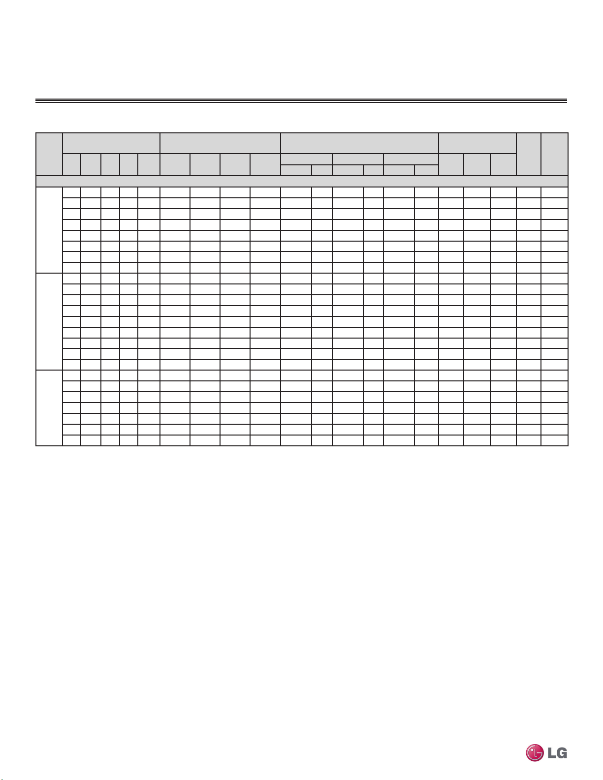
MULTI
F
MAX
MULTI
F
PERFORMANCE DATA
Rated Cooling Combination Tables
Table 21: LMU36CHV with Ducted Indoor Units — Rated Cooling Combination Table.
Indoor Unit Combination
No. of
Indoor
IDU 1IDU 2IDU 3IDU
Units
Ducted Indoor Units
12 12 - - 24 10,500 10,500 - - 12,600 3.7 21,000 6.2 23,310 6.8 1,578 2,255 3,157 9.3 15.4
Two
12 18 - - 30 10,500 15,750 - - 15,750 4.6 26,250 7.7 29,138 8.5 1,904 2,720 3,808 9.6 16.0
Units
18 18 - - 36 14,000 14,000 - - 16,800 4.9 28,000 8.2 31,080 9.1 1,998 2,855 3,997 9.8 16.2
12 24* - - 36 9,333 18,667 - - 16,800 4.9 28,000 8.2 31,080 9.1 1,998 2,855 3,997 9.8 16.2
Three
12 12 12 - 36 9,333 9,333 9,333 - 16,800 4.9 28,000 8.2 32,200 9.4 1,868 2,669 3,736 10.5 17.4
Units
12 12 18 - 42 8,000 8,000 12,000 - 16,800 4.9 28,000 8.2 32,200 9.4 1,868 2,669 3,736 10.5 17.4
12 18 18 - 48 7,000 10,500 10,500 - 16,800 4.9 28,000 8.2 32,200 9.4 1,868 2,669 3,736 10.5 17.4
Four
Units
1
0 ft. level difference between outdoor and indoor units.
2
bulb (WB), and outdoor ambient conditions of 95ºF dry bulb (DB) and 75ºF wet bulb (WB).
3
4
12 12 12 12 48 7,000 7,000 7,000 7,000 16,800 4.9 28,000 8.2 33,600 9.8 1,782 2,545 3,564 11.0 18.2
Capacity as rated: 0 ft. above sea level with 25 ft. of refrigerant piping.
Cooling capacity rating obtained with air entering the indoor unit at 80ºF dry bulb (DB) and 67ºF wet
Wiring cable size must comply with the applicable local and national codes.
The specification may be subject to change without prior notice for purpose of improvement.
(kBtu/h)
Total
4
9 9 - - 18 7,875 7,875 - - 9,450 2.8 15,750 4.6 17,483 5.1 1,245 1,779 2,491 8.9 14.6
9 12 - - 21 7,875 10,500 - - 11,025 3.2 18,375 5.4 20,396 6.0 1,426 2,038 2,853 9.0 14.9
9 18 - - 27 7,875 15,750 - - 14,175 4.2 23,625 6.9 26,224 7.7 1,752 2,503 3,504 9.4 15.6
9 24* - - 33 7,636 20,364 - - 16,800 4.9 28,000 8.2 31,080 9.1 1,998 2,855 3,997 9.8 16.2
9 9 9 - 27 7,875 7,875 7,875 - 14,175 4.2 23,625 6.9 27,169 8.0 1,665 2,379 3,331 9.9 16.4
9 9 12 - 30 7,875 7,875 10,500 - 15,750 4.6 26,250 7.7 30,188 8.8 1,781 2,544 3,562 10.3 17.1
9 12 12 - 33 7,636 10,182 10,182 - 16,800 4.9 28,000 8.2 32,200 9.4 1,868 2,669 3,736 10.5 17.4
9 9 18 - 36 7,000 7,000 14,000 - 16,800 4.9 28,000 8.2 32,200 9.4 1,868 2,669 3,736 10.5 17.4
9 12 18 - 39 6,462 8,615 12,923 - 16,800 4.9 28,000 8.2 32,200 9.4 1,868 2,669 3,736 10.5 17.4
9 18 18 - 45 5,600 11,200 11,200 - 16,800 4.9 28,000 8.2 32,200 9.4 1,868 2,669 3,736 10.5 17.4
9 9 9 9 36 7,000 7,000 7,000 7,000 16,800 4.9 28,000 8.2 33,600
9 9 9 12 39 6,462 6,462 6,462 8,615 16,800 4.9 28,000 8.2 33,600 9.8 1,782 2,545 3,564 11.0 18.2
9 9 12 12 42 6,000 6,000 8,000 8,000 16,800 4.9 28,000 8.2 33,600 9.8 1,782 2,545 3,564 11.0 18.2
9 9 9 18 45 5,600 5,600 5,600 11,200 16,800 4.9 28,000 8.2 33,600 9.8 1,782 2,545 3,564 11.0 18.2
9 12 12 12 45 5,600 7,467 7,467 7,467 16,800 4.9 28,000 8.2 33,600 9.8 1,782 2,545 3,564 11.0 18.2
9 9 12 18 48 5,250 5,250 7,000 10,500 16,800 4.9 28,000 8.2 33,600 9.8 1,782 2,545 3,564 11.0 18.2
Room Capacity Total Capacity Input (W)
Unit 1
(Btu/h)
Unit 2
(Btu/h)
Unit 3
(Btu/h)
Unit 4
(Btu/h)
Minimum Rated Maximum
Btu/h kW Btu/h kW Btu/h kW
5
At least two indoor units should be connected.
*A 1.3 multiplier is necessary for the calculation of total combination.
EER SEER
Min. Rated Max.
9.8 1,782 2,545 3,564 11.0 18.2
Multi F and Multi F MAX Heat Pump System Engineering Manual
28 | MULTI F OUTDOOR UNIT
Due to our policy of continuous product innovation, some specications may change without notication.
©LG Electronics U.S.A., Inc., Englewood Cliffs, NJ. All rights reserved. “LG” is a registered trademark of LG Corp.

MULTI
F
MAX
MULTI
F
Table 22: LMU36CHV with Mixed Indoor Units — Rated Cooling Combination Table.
1
0 ft. level difference between outdoor and indoor units.
2
bulb (WB), and outdoor ambient conditions of 95ºF dry bulb (DB) and 75ºF wet bulb (WB).
PERFORMANCE DATA
Rated Cooling Combination Tables
Indoor Unit Combination
No. of
Indoor
IDU 1IDU 2IDU 3IDU
Units
(kBtu/h)
Total
4
(Btu/h)
Mixed Indoor Units
7 9 - - 16 6,563 8,438 - - 9,000 2.6 15,000 4.4 16,650 4.9 1,089 1,556 2,179 9.6 16.2
9 9 - - 18 8,438 8,438 - - 10,125 3.0 16,875 4.9 18,731 5.5 1,225 1,750 2,449 9.6 16.2
7 12 - - 19 6,563 11,250 - - 10,688 3.1 17,813 5.2 19,772 5.8 1,282 1,831 2,563 9.7 16.3
9 12 - - 21 8,438 11,250 - - 11,813 3.5 19,688 5.8 21,853 6.4 1,403 2,004 2,805 9.8 16.5
9 15 - - 24 8,438 14,063 - - 13,500 4.0 22,500 6.6 24,975 7.3 1,552 2,217 3,104 10.1 17.0
12 12 - - 24 11,250 11,250 - - 13,500 4.0 22,500 6.6 24,975 7.3 1,552 2,217 3,104 10.1 17.0
7 18 - - 25 6,563 16,875 - - 14,063 4.1 23,438 6.9 26,016 7.6 1,609 2,299 3,218 10.2 17.1
9 18 - - 27 8,438 16,875 - - 15,188 4.5 25,313 7.4 28,097 8.2 1,723 2,462 3,446 10.3 17.2
Two
12 15 - - 27 11,250 14,063 - - 15,188 4.5 25,313 7.4 28,097 8.2 1,723 2,462 3,446 10.3 17.2
12 18 - - 30 11,250 16,875 - - 16,875 4.9 28,125 8.2 31,219 9.1 1,873 2,675 3,745 10.5 17.6
Units
7 24 - - 31 6,563 22,500 - - 17,438 5.1 29,063 8.5 32,259 9.5 1,915 2,736 3,831 10.6 17.8
9 24 - - 33 8,182 21,818 - - 18,000 5.3 30,000 8.8 33,300 9.8 1,965 2,807 3,930 10.7 17.9
15 18 - - 33 13,636 16,364 - - 18,000 5.3 30,000 8.8 33,300 9.8 1,965 2,807 3,930 10.7 17.9
18 18 - - 36 15,000 15,000 - - 18,000 5.3 30,000 8.8 33,300 9.8 1,965 2,807 3,930 10.7 17.9
12 24 - - 36 10,000 20,000 - - 18,000 5.3 30,000 8.8 33,300 9.8 1,965 2,807 3,930 10.7 17.9
15 24 - - 39 11,538 18,462 - - 18,000 5.3 30,000 8.8 33,300 9.8 1,965 2,807 3,930 10.7 17.9
18 24* - - 42 12,857 17,143 - - 18,000 5.3 30,000 8.8 33,300 9.8 1,965 2,807 3,930 10.7 17.9
24* 24* - - 48 15,000 15,000 - - 18,000 5.3 30,000 8.8 33,300 9.8 1,965 2,807 3,930
7 7 9 - 23 6,563 6,563 8,438 - 12,938 3.8 21,563 6.3 24,797 7.3 1,467 2,095 2,933 10.3 17.3
7 9 9 - 25 6,563 8,438 8,438 - 14,063 4.1 23,438 6.9 26,953 7.9 1,581 2,258 3,161 10.4 17.4
7 7 12 - 26 6,563 6,563 11,250 - 14,625 4.3 24,375 7.1 28,031 8.2 1,609 2,299 3,218 10.6 17.8
9 9 9 - 27 8,438 8,438 8,438 - 15,188 4.5 25,313 7.4 29,109 8.5 1,638 2,339 3,275 10.8 18.1
7 9 12 - 28 6,563 8,438 11,250 - 15,750 4.6 26,250 7.7 30,188 8.8 1,673 2,390 3,346 11.0 18.4
9 9 12 - 30 8,438 8,438 11,250 - 16,875 4.9 28,125 8.2 32,344 9.5 1,752 2,502 3,503 11.2 18.9
7 9 15 - 31 6,563 8,438 14,063 - 17,438 5.1 29,063 8.5 33,422 9.8 1,794 2,563 3,589 11.3 19.0
7 12 12 - 31 6,563 11,250 11,250 - 17,438 5.1 29,063 8.5 33,422 9.8 1,794 2,563 3,589 11.3 19.0
7 7 18 - 32 6,563 6,563 16,875 - 18,000 5.3 30,000 8.8 34,500 10.1 1,837 2,624 3,674 11.4 19.2
9 9 15 - 33 8,182 8,182 13,636 - 18,000 5.3 30,000 8.8 34,500 10.1 1,837 2,624 3,674 11.4 19.2
9 12 12 - 33 8,182 10,909 10,909 - 18,000 5.3 30,000 8.8 34,500 10.1 1,837 2,624 3,674 11.4 19.2
7 9 18 - 34 6,176 7,941 15,882 - 18,000 5.3 30,000 8.8 34,500 10.1 1,837 2,624 3,674 11.4 19.2
7 12 15 - 34 6,176 10,588 13,235 - 18,000 5.3 30,000 8.8 34,500 10.1 1,837 2,624 3,674 11.4 19.2
9 9 18 - 36 7,500 7,500 15,000 - 18,000 5.3 30,000 8.8 34,500 10.1 1,837 2,624 3,674 11.4 19.2
Three
Capacity as rated: 0 ft. above sea level with 25 ft. of refrigerant piping.
Cooling capacity rating obtained with air entering the indoor unit at 80ºF dry bulb (DB) and 67ºF wet
9 12 15 - 36 7,500 10,000 12,500 - 18,000 5.3 30,000 8.8 34,500 10.1 1,837 2,624 3,674 11.4 19.2
12 12 12 - 36 10,000 10,000 10,000 - 18,000 5.3 30,000 8.8 34,500 10.1 1,837 2,624 3,674 11.4 19.2
Units
7 12 18 - 37 5,676 9,730 14,595 - 18,000 5.3 30,000 8.8 34,500 10.1 1,837 2,624 3,674 11.4 19.2
7 7 24 - 38 5,526 5,526 18,947 - 18,000 5.3 30,000 8.8 34,500 10.1 1,837 2,624 3,674 11.4 19.2
9 12 18 - 39 6,923 9,231 13,846 - 18,000 5.3 30,000 8.8 34,500 10.1 1,837 2,624 3,674 11.4 19.2
9 15 15 - 39 6,923 11,538 11,538 - 18,000 5.3 30,000 8.8 34,500 10.1 1,837
12 12 15 - 39 9,231 9,231 11,538 - 18,000 5.3 30,000 8.8 34,500 10.1 1,837 2,624 3,674 11.4 19.2
7 9 24 - 40 5,250 6,750 18,000 - 18,000 5.3 30,000 8.8 34,500 10.1 1,837 2,624 3,674 11.4 19.2
7 15 18 - 40 5,250 11,250 13,500 - 18,000 5.3 30,000 8.8 34,500 10.1 1,837 2,624 3,674 11.4 19.2
9 9 24* - 42 6,429 6,429 17,143 - 18,000 5.3 30,000 8.8 34,500 10.1 1,837 2,624 3,674 11.4 19.2
9 15 18 - 42 6,429 10,714 12,857 - 18,000 5.3 30,000 8.8 34,500 10.1 1,837 2,624 3,674 11.4 19.2
12 12 18 - 42 8,571 8,571 12,857 - 18,000 5.3 30,000 8.8 34,500 10.1 1,837 2,624 3,674 11.4 19.2
12 15 15 - 42 8,571 10,714 10,714 - 18,000 5.3 30,000 8.8 34,500 10.1 1,837 2,624 3,674 11.4 19.2
7 12 24* - 43 4,884 8,372 16,744 - 18,000 5.3 30,000 8.8 34,500 10.1 1,837 2,624 3,674 11.4 19.2
7 18 18 - 43 4,884 12,558 12,558 - 18,000 5.3 30,000 8.8 34,500 10.1 1,837 2,624 3,674 11.4 19.2
9 12 24* - 45 6,000 8,000 16,000 - 18,000 5.3 30,000 8.8 34,500 10.1 1,837 2,624 3,674 11.4 19.2
9 18 18 - 45 6,000 12,000 12,000 - 18,000 5.3 30,000 8.8 34,500 10.1 1,837 2,624 3,674 11.4 19.2
Room Capacity Total Capacity Input (W)
Unit 1
Unit 2
(Btu/h)
Due to our policy of continuous product innovation, some specications may change without notication.
©LG Electronics U.S.A., Inc., Englewood Cliffs, NJ. All rights reserved. “LG” is a registered trademark of LG Corp.
Unit 3
(Btu/h)
Unit 4
(Btu/h)
Minimum Rated Maximum
Btu/h kW Btu/h kW Btu/h kW
3
Wiring cable size must comply with the applicable local and national codes.
4
The specification may be subject to change without prior notice for purpose of improvement.
5
At least two indoor units should be connected.
*The indoor unit must be non-ducted type.
Min. Rated Max.
EER SEER
Multi F Outdoor Unit Data
10.7 17.9
2,624 3,674 11.4 19.2
MULTI F OUTDOOR UNIT | 29
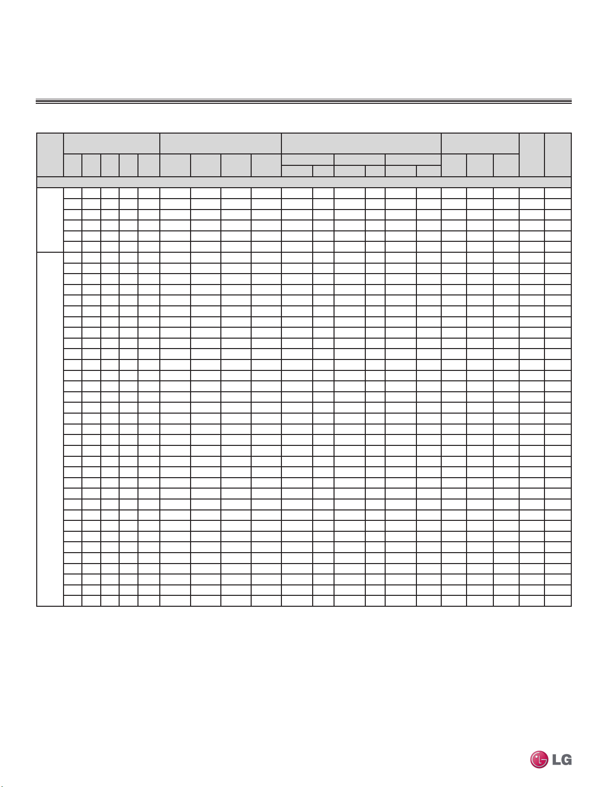
MULTI
F
MAX
MULTI
F
PERFORMANCE DATA
Rated Cooling Combination Tables
Table 23: LMU36CHV with Mixed Indoor Units — Rated Cooling Combination Table.
Indoor Unit Combination
No. of
Indoor
IDU 1IDU 2IDU 3IDU
Units
Mixed Indoor Units
Three
Units
Four
Units
Multi F and Multi F MAX Heat Pump System Engineering Manual
1
Capacity as rated: 0 ft. above sea level with 25 ft. of refrigerant piping.
0 ft. level difference between outdoor and indoor units.
2
Cooling capacity rating obtained with air entering the indoor unit at 80ºF dry bulb (DB) and 67ºF wet
bulb (WB), and outdoor ambient conditions of 95ºF dry bulb (DB) and 75ºF wet bulb (WB).
3
Wiring cable size must comply with the applicable local and national codes.
(kBtu/h)
Total
4
12 15 18 - 45 8,000 10,000 12,000 - 18,000 5.3 30,000 8.8 34,500 10.1 1,837 2,624 3,674 11.4 19.2
7 15 24* - 46 4,565 9,783 15,652 - 18,000 5.3 30,000 8.8 34,500 10.1 1,837 2,624 3,674 11.4 19.2
9 15 24* - 48 5,625 9,375 15,000 - 18,000 5.3 30,000 8.8 34,500 10.1 1,837 2,624 3,674 11.4 19.2
12 12 24* - 48 7,500 7,500 15,000 - 18,000 5.3 30,000 8.8 34,500 10.1 1,837 2,624 3,674 11.4 19.2
12 18 18 - 48 7,500 11,250 11,250 - 18,000 5.3 30,000 8.8 34,500 10.1 1,837 2,624 3,674 11.4 19.2
15 15 18 - 48 9,375 9,375 11,250 - 18,000 5.3 30,000 8.8 34,500 10.1 1,837 2,624 3,674 11.4 19.2
7 7 7 9 30 6,563 6,563 6,563 8,438 16,875 4.9 28,125 8.2 33,750 9.9 1,673 2,390 3,346 11.8 19.7
7 7 9 9 32 6,563 6,563 8,438 8,438 18,000 5.3 30,000 8.8 36,000 10.6 1,752 2,503 3,505 12.0 20.1
7 7 7 12 33 6,364 6,364 6,364 10,909 18,000 5.3 30,000 8.8 36,000 10.6 1,752 2,503 3,505 12.0 20.1
7 9 9 9 34 6,176 7,941 7,941 7,941 18,000 5.3 30,000 8.8 36,000 10.6 1,752 2,503 3,505 12.0 20.1
7 7 9 12 35 6,000 6,000 7,714 10,286 18,000 5.3 30,000 8.8 36,000 10.6 1,752 2,503 3,505 12.0 20.1
9 9 9 9 36 7,500 7,500 7,500 7,500 18,000 5.3 30,000 8.8 36,000 10.6 1,752 2,503 3,505 12.0 20.1
7 9 9 12 37 5,676 7,297 7,297 9,730 18,000 5.3 30,000 8.8 36,000 10.6 1,752 2,503 3,505 12.0 20.1
7 7 9 15 38 5,526 5,526 7,105 11,842 18,000 5.3 30,000 8.8 36,000 10.6 1,752 2,503 3,505 12.0 20.1
7 7 12 12 38 5,526 5,526 9,474 9,474 18,000 5.3 30,000 8.8 36,000 10.6 1,752 2,503 3,505 12.0 20.1
7 7 7 18 39 5,385 5,385 5,385 13,846 18,000 5.3 30,000 8.8 36,000 10.6 1,752 2,503 3,505 12.0 20.1
9 9 9 12 39 6,923 6,923 6,923 9,231 18,000 5.3 30,000 8.8 36,000 10.6 1,752 2,503 3,505 12.0 20.1
7 9 9 15 40 5,250 6,750 6,750 11,250 18,000 5.3 30,000 8.8 36,000 10.6 1,752
7 9 12 12 40 5,250 6,750 9,000 9,000 18,000 5.3 30,000 8.8 36,000 10.6 1,752 2,503 3,505 12.0 20.1
7 7 9 18 41 5,122 5,122 6,585 13,171 18,000 5.3 30,000 8.8 36,000 10.6 1,752 2,503 3,505 12.0 20.1
7 7 12 15 41 5,122 5,122 8,780 10,976 18,000 5.3 30,000 8.8 36,000 10.6 1,752 2,503 3,505 12.0 20.1
9 9 9 15 42 6,429 6,429 6,429 10,714 18,000 5.3 30,000 8.8 36,000 10.6 1,752 2,503 3,505 12.0 20.1
9 9 12 12 42 6,429 6,429 8,571 8,571 18,000 5.3 30,000 8.8 36,000 10.6 1,752 2,503 3,505 12.0 20.1
7 9 9 18 43 4,884 6,279 6,279 12,558 18,000 5.3 30,000 8.8 36,000 10.6 1,752 2,503 3,505 12.0 20.1
7 9 12 15 43 4,884 6,279 8,372 10,465 18,000 5.3 30,000 8.8 36,000 10.6 1,752 2,503 3,505 12.0 20.1
7 12 12 12 43 4,884 8,372 8,372 8,372 18,000 5.3 30,000 8.8 36,000 10.6 1,752 2,503 3,505 12.0 20.1
7 7 12 18 44 4,773 4,773 8,182 12,273 18,000 5.3 30,000 8.8 36,000 10.6 1,752 2,503 3,505 12.0 20.1
7 7 7 24* 45 4,667 4,667 4,667 16,000 18,000 5.3 30,000 8.8 36,000 10.6 1,752 2,503 3,505 12.0 20.1
9 9 9 18 45 6,000 6,000 6,000 12,000 18,000 5.3 30,000 8.8 36,000 10.6 1,752 2,503 3,505 12.0 20.1
9 9 12 15 45 6,000 6,000 8,000 10,000 18,000 5.3 30,000 8.8 36,000 10.6 1,752 2,503 3,505 12.0 20.1
9 12 12 12 45 6,000 8,000 8,000 8,000 18,000 5.3 30,000 8.8 36,000 10.6 1,752 2,503 3,505 12.0 20.1
7 9 12 18 46 4,565 5,870 7,826 11,739 18,000 5.3 30,000 8.8 36,000 10.6 1,752 2,503 3,505 12.0 20.1
7 9 15 15 46 4,565 5,870 9,783 9,783 18,000 5.3 30,000 8.8 36,000 10.6 1,752 2,503 3,505 12.0 20.1
7 12 12 15 46 4,565 7,826 7,826 9,783 18,000 5.3 30,000 8.8 36,000 10.6 1,752 2,503 3,505 12.0 20.1
7 7 9 24* 47 4,468 4,468 5,745 15,319 18,000 5.3 30,000 8.8 36,000 10.6 1,752 2,503 3,505 12.0 20.1
7 7 15 18 47 4,468 4,468 9,574 11,489 18,000 5.3 30,000 8.8 36,000 10.6 1,752 2,503 3,505 12.0 20.1
9 9 12 18 48 5,625 5,625 7,500 11,250 18,000 5.3 30,000 8.8 36,000 10.6 1,752 2,503 3,505 12.0 20.1
9 9 15 15 48 5,625 5,625 9,375 9,375 18,000 5.3 30,000 8.8 36,000 10.6 1,752
12 12 12 12 48 7,500 7,500 7,500 7,500 18,000 5.3 30,000 8.8 36,000 10.6 1,752 2,503 3,505 12.0 20.1
(Btu/h)
Room Capacity Total Capacity Input (W)
Unit 1
Unit 2
(Btu/h)
Unit 3
(Btu/h)
Unit 4
(Btu/h)
Minimum Rated Maximum
Btu/h kW Btu/h kW Btu/h kW
4
The specification may be subject to change without prior notice for purpose of improvement.
5
At least two indoor units should be connected.
*The indoor unit must be non-ducted type.
EER SEER
Min. Rated Max.
2,503 3,505 12.0 20.1
2,503 3,505 12.0 20.1
30 | MULTI F OUTDOOR UNIT
Due to our policy of continuous product innovation, some specications may change without notication.
©LG Electronics U.S.A., Inc., Englewood Cliffs, NJ. All rights reserved. “LG” is a registered trademark of LG Corp.
 Loading...