

LG LF-K5932A Owner’s Manual
DVD MINI KARAOKE SYSTEM
OWNER’S MANUAL
MODEL : LF-K5932
LF-K5932A, LF-KP5932
LFS-K5932V, LFS-K5932C, LFS-K5932T
Please read this manual carefully before operating your set.
Retain it for future reference.
Designs and specifications are subject to change without
notice for improvement.
LGESA-LF-K5932A_ENG_MFL39518842
R
2
Safety Precautions
This lightning flash with arrowhead symbol within an
equilateral triangle is intended to alert the user to
the presence of uninsulated dangerous voltage
within the product’s enclosure that may be of
sufficient magnitude to constitute a risk of electric
shock to persons.
The exclamation point within an equilateral triangle
is intended to alert the user to the presence of
important operating and maintenance (servicing)
instructions in the literature accompanying the
appliance.
CAUTION:
This unit employs a Laser System.
To ensure proper use of this product, please read this owner’s
manual carefully and retain for future reference, should the unit
require maintenance, contact an authorized service locationsee service procedure.
Use of controls, adjustments or the performance of procedures
other than those specified herein may result in hazardous
radiation exposure.
To prevent direct exposure to laser beam, do not try to open
the enclosure. Visible laser radiation when open. DO NOT
STARE INTO BEAM.
CAUTION: The apparatus shall not be exposed to water,
dripping or splashing and that no objects filled with liquids,
such as vases, shall be placed on the apparatus.
CAUTION concerning the Power Cord
Most appliances recommend they be placed upon a dedicated circuit;
That is, a single outlet circuit which powers only that appliance
and has no additional outlets or branch circuits. Check the
specification page of this owner's manual to be certain.
Do not overload wall outlets. Overloaded wall outlets, loose or
damaged wall outlets, extension cords, frayed power cords, or
damaged or cracked wire insulation are dangerous. Any of
these conditions could result in electric shock or fire.
Periodically examine the cord of your appliance, and if its
appearance indicates damage or deterioration, unplug it, discontinue use of the appliance, and have the cord replaced with
an exact replacement part by an authorized servicer.
Protect the power cord from physical or mechanical abuse,
such as being twisted, kinked, pinched, closed in a door, or
walked upon. Pay particular attention to plugs, wall outlets, and
the point where the cord exits the appliance.
WARNING: TO REDUCE THE RISK OF FIRE OR ELECTRIC SHOCK, DO NOT EXPOSE THIS PRODUCT TO
RAIN OR MOISTURE.
CAUTION
RISK OF ELECTRIC SHOCK
DO NOT OPEN
WARNING: TO REDUCE THE RISK
OF ELECTRIC SHOCK
DO NOT REMOVE COVER (OR BACK)
NO USER-SERVICEABLE PARTS INSIDE
REFER SERVICING TO QUALIFIED SERVICE
PERSONNEL.
INTRODUCTION
3
Table of Contents
Introduction
Safety Precautions. . . . . . . . . . . . . . . . . . . . . . . . . . . . . . . . 2
Table of Contents. . . . . . . . . . . . . . . . . . . . . . . . . . . . . . . . . 3
Before Use . . . . . . . . . . . . . . . . . . . . . . . . . . . . . . . . . . . . . 3
Front Panel . . . . . . . . . . . . . . . . . . . . . . . . . . . . . . . . . . . . . 4
Rear Panel . . . . . . . . . . . . . . . . . . . . . . . . . . . . . . . . . . . . . 5
Remote Control . . . . . . . . . . . . . . . . . . . . . . . . . . . . . . . . . . 6
Preparation
Connections . . . . . . . . . . . . . . . . . . . . . . . . . . . . . . . . . . 7-11
Before Operation. . . . . . . . . . . . . . . . . . . . . . . . . . . . . . 12-20
Operation
Operation with DVD . . . . . . . . . . . . . . . . . . . . . . . . . . 21-23
Operation with Audio CD and MP3/WMA Disc . . . . . . . 23-24
Programmed Playback . . . . . . . . . . . . . . . . . . . . . . . . . . . 24
Operation with JPEG Disc . . . . . . . . . . . . . . . . . . . . . . . . . 25
Operation with DivX Disc . . . . . . . . . . . . . . . . . . . . . . . . . 26
Operation with RADIO . . . . . . . . . . . . . . . . . . . . . . . . . . . . 27
Operation with TAPE . . . . . . . . . . . . . . . . . . . . . . . . . . . . . 28
Recording . . . . . . . . . . . . . . . . . . . . . . . . . . . . . . . . . . . . . 28
Operation with KARAOKE . . . . . . . . . . . . . . . . . . . . . . 29-33
Reference
Troubleshooting . . . . . . . . . . . . . . . . . . . . . . . . . . . . . . . . . 34
Language Code List. . . . . . . . . . . . . . . . . . . . . . . . . . . . . . 35
Country Code List . . . . . . . . . . . . . . . . . . . . . . . . . . . . . . . 35
Specifications
About Symbols
About the symbol display
“ ” may appear on the TV screen during operation.
This icon means the function explained in this owner’s
manual is not available on that specific DVD video disc.
About the disc symbols for instructions
A section whose title has one of the following symbol is
applicable only to the disc represented by the symbol.
DVD
Audio CDs
MP3 disc
WMA disc
JPEG disc
DivX disc
About the symbols for instructions
Indicates hazards likely to cause harm to the unit itself or
other material damage.
Indicates special operating features of this unit.
Indicates tips and hints for making the task easier.
DivX
JPEG
WMA
MP3
CD
DVD
Before Use
Playable Discs
DVD
(8 cm / 12 cm disc)
Audio CD
(8 cm / 12 cm disc)
In addition, this unit can play a DVD±R, DVD±RW and
CD-R or CD-RW that contains audio titles, MP3, WMA,
JPEG or DivX files.
Notes
– Depending on the conditions of the recording equip-
ment or the CD-R/RW (or DVD±R/RW) disc itself,
some CD-R/RW (or DVD±R/RW) discs cannot be
played on the unit.
– Do not attach any seal or label to either side (the
labeled side or the recorded side) of a disc.
–
Do not use irregularly shaped CDs (e.g., heart-shaped
or octagonal). It may result in malfunctions.
Regional code of the DVD player and DVDs
This DVD player is designed and manufactured
for playback of region “2” encoded DVD software. The region code on the labels of some
DVD discs indicates which type of player can
play those discs. This unit can play only DVD discs
labeled “2” or “ALL”. If you try to play any other discs, the
message “Check Regional Code” will appear on the TV
screen. Some DVD discs may not have a region code
label even though their playback is prohibited by area
limits.
ote on DTS-encoded CDs
When playing DTS-encoded CDs, excessive audio level
may be heard from the analog stereo output. To avoid
possible damage to the audio system, turn down the
volume before playing back such discs, adjust the volume gradually, and keep the volume level low. To enjoy
DTS Digital Surround
TM
playback, an external 5.1 channel DTS Digital SurroundTMdecoder system must be
connected to the digital output of the unit.
2
4
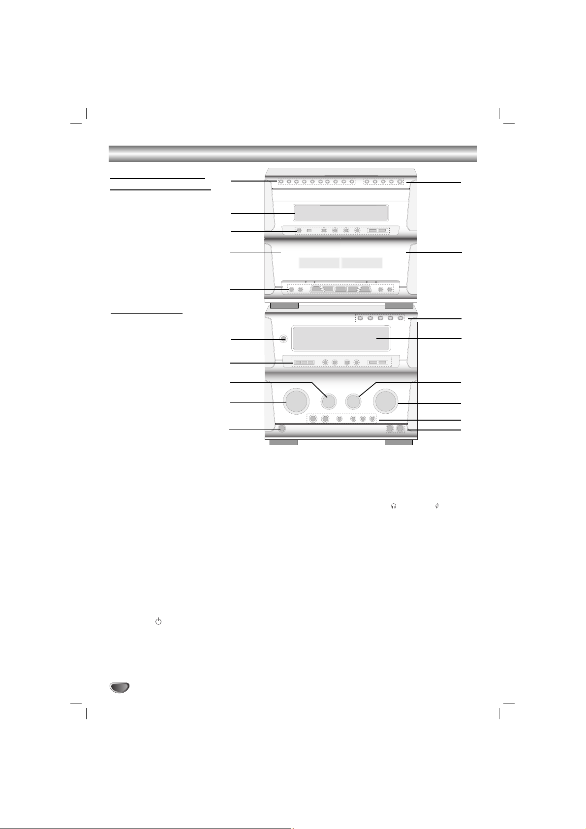
Front Panel
1. NUMERIC buttons (0~9)
2. DISPLAY WINDOW
3. • PLAY MODE/ REPEAT buttons
• CD SEARCH (
FF/GG
) buttons
• CD STOP (xSTOP)/ CD PLAY (
G
) buttons
• CD PAUSE ([])/ PROGRAM button
4. Z PUSH EJECT position (TAPE 1)
5. TAPE FUNCTION buttons
• COUNTER RESET (COUNT. RESET) button
• RECORD/ RECORD PAUSE (zREC/[]) button
• REWIND/ FAST FORWARD (
FF/GG
) buttons
• REVERSE PLAY (
F
)/ PLAY (G) buttons
• STOP (x) button
• NORMAL DUBBING/ CD SYNCHRO RECORDING
(CD SYNC.) button
• HIGH DUBBING button
6. POWER ( STANDBY/ON) button
7. • CLOCK/ TIMER/ MEMORY/ CLEAR buttons
• PRESET (
▼/▲
) buttons
• AUTO TUNING (
▼/▲
) buttons
• SET button
• MODE/RIF/DEMO button
8. ECHO VOLUME KNOB (ECHO VOL.)
9. MULTI JOG DIAL
• CD SKIP (./>)
• MANUAL TUNING
• CLOCK ADJUST
10. HEADPHONE SOCKET ( PHONES) - 6.3mm
11. MIC JACKS (MIC1, MIC2)
12. XDSS/ OAO/ SURROUND/ MUSIC/ DANCE/ USER
buttons
13. VOLUME knob
14. MIC VOLUME KNOB (MIC VOL.)
15. DISPLAY WINDOW
16. FUNCTION SELECT buttons
(TUNER/BAND, TAPE 1-2, DVD/CD/KARAOKE,
AUX1/ AUX2)
17. Z PUSH EJECT position (TAPE 2)
18. •
DISC DIRECT PLAY buttons (DISC1, DISC2, DISC3)
• DISC SKIP button (D. SKIP)
• CD OPEN/CLOSE button (Z OPEN/CLOSE)
7
8
6
9
5
11
2
3
4
10
12
13
14
15
16
17
18
Cassette tape player/
DVD/KARAOKE player
Tuner/ Amplifier
1
5
INTRODUCTION
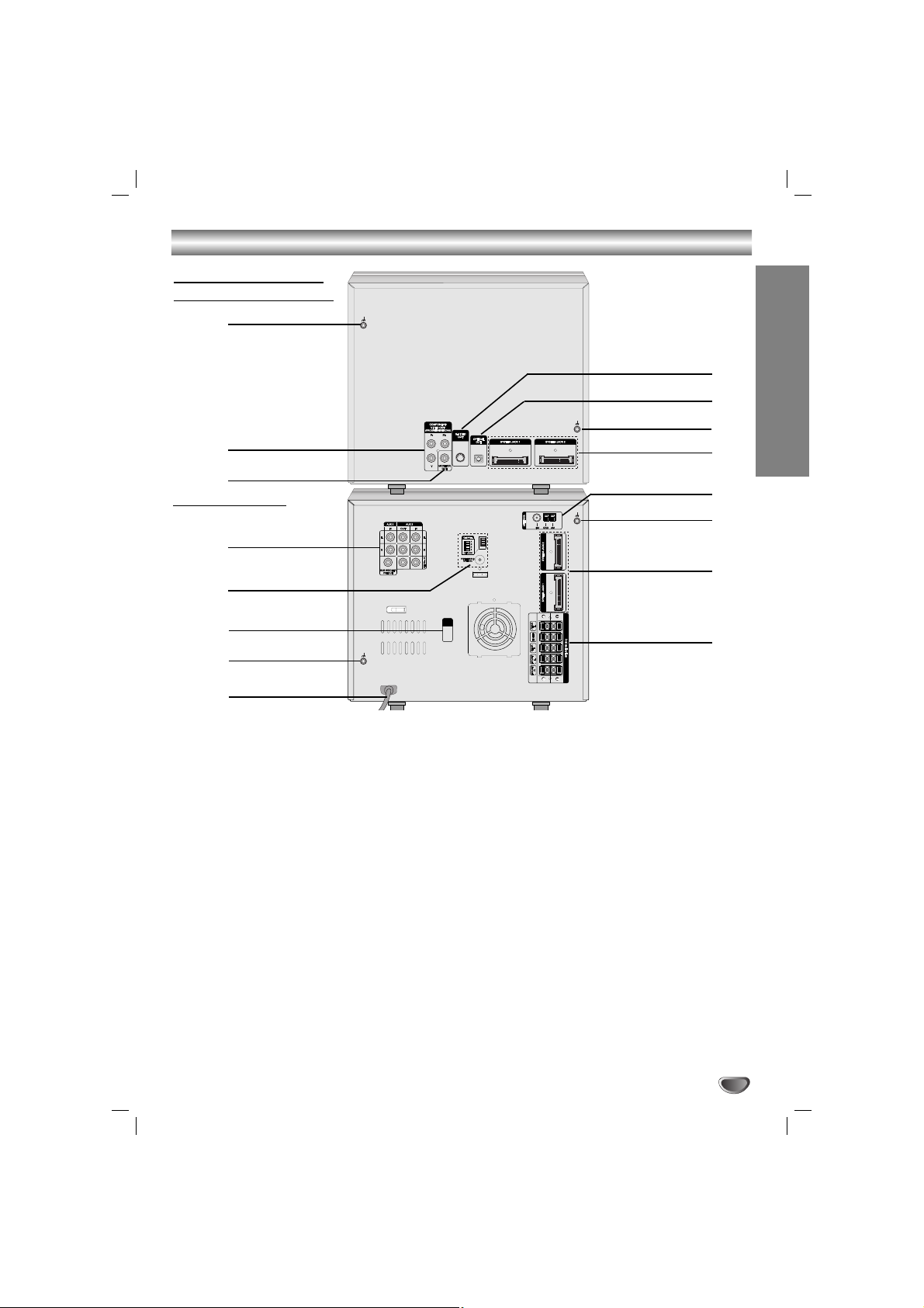
Rear Panel
.
2
3
11
4
6
9
10
12
13
15
16
1. LUG Connector
2.
COMPONENT VIDEO OUT (PROGRESSIVE SCAN)
(Y Pb Pr) Connector
3. MONITOR OUT Connector
4. • VIDEO INPUT/OUTPUT
• AUX 1 INPUT (L/R)
• AUX 2 INPUT/OUTPUT (L/R)
• SUB WOOFER OUTPUT
5. • WIRELESS MIC CHANNEL SWITCH
• WIRELESS MIC ANTENNA Connector
6. VOLTAGE SELECTOR : OPTIONAL
7. LUG Connector
8. POWER CORD
9. SPEAKER Connector
10. SYSTEM Connector
(SYSTEM JACK1/ SYSTEM JACK2)
11. LUG Connector
12. ANTENNA Connector
13. SYSTEM Connector
(SYSTEM JACK1/ SYSTEM JACK2)
14. LUG Connector
15. OPTICAL OUT Connector
16. S-VIDEO OUT Connector
Cassette tape player/
DVD/KARAOKE Player
Tuner/ Amplifier
5
7
11
14
8
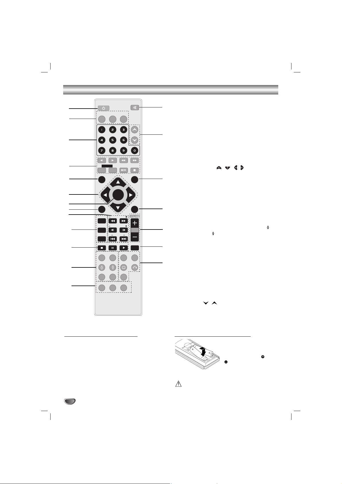
Remote Control
6
Remote Control Operation Range
Point the remote control at the remote sensor and press
the buttons.
Distance: About 23 ft (7 m) from the front of the
remote sensor
Angle: About 30° in each direction of the front of the
remote sensor
Remote control battery installation
Detach the battery cover on
the rear of the remote control, and insert two R03 (size
AAA) batteries with and
aligned correctly.
Caution
Do not mix old and new batteries. Never mix different
types of batteries (standard, alkaline, etc.).
1. POWER button
2. FUNCTION SELECT buttons
(TUNER/BAND, DVD/KARAOKE, AUX1/2)
3. NUMERIC buttons (0-9)
4. TAPE FUNCTION buttons
- REVERSE PLAY (
F
)
- PLAY (
G
)
- REWIND/ FAST FORWARD PLAY (
FF/GG
)
- TAPE 1/2 SELECT buttons
- RECORD/ RECORD PAUSE (z/[])
- TAPE STOP (x)
5. SET UP button
6. ARROW buttons ( / //)
(For use in highlighting a selection on a GUI menu
screen, TITLE and MENU screen.)
7. SELECT/ENTER button
8. MENU button
(Use the MENU button to display the menu screen
included on DVD video discs.)
9. SCAN (
FF/GG
)/ TEMPO (-/+)/ SLOW (t/T)/
KEY CONTROL (#/b)/ SKIP (./>) buttons
10. PROGRAM/ REPEAT/ REPEAT A-B buttons
11. STO P ( x), PAUSE([])/ STEP, PLAY (
G
) buttons
12. EQUALIZER (EQ)/ OAO/ SOUND/ FEMALE( )
AUDIO/ MALE( )/ CLEAR/ SHADOW buttons
13. DIMMER/ SLEEP/ SPECTRUM buttons
14. •
SURROUND (SURR.)/ XDSS/ SUBTITLE (S-TITLE)/
RETURN buttons
•
CHORUS button
(
When a Song with chorus function is played, use
this button.)
15. DISC SKIP (D.SKIP) buttons
16. VOLUME -/+ buttons
17. TITLE button
(Use the TITLE button to display the title screen
included on DVD video discs.)
18. DISPLAY button
19. PRESET (
/ ) buttons
20. MUTE button
POWER
1
6
5
4
3
2
8
9
20
19
17
15
16
18
7
10
12
13
14
11
TUNER/BAND
DVD/
KARAOKE
MUTE
AUX1/2
PRESET
1 - TAPE - 2
SET UP
DISPLAY
SELECT
/ENTER
MENU
PROGRAM
TEMPO
SLOW
REPEAT
REPEAT A-B
STOP D.SKIP
PAUSE/STEP
OAO SURR. XDSS
EQ
KEY CONb
#
PLAY
SOUND AUDIO S-TITLE RETURN
CHORUS
SHADOW
CLEAR
SLEEP SPECTRUM
DIMMER
TITLE
PREPARATION
7
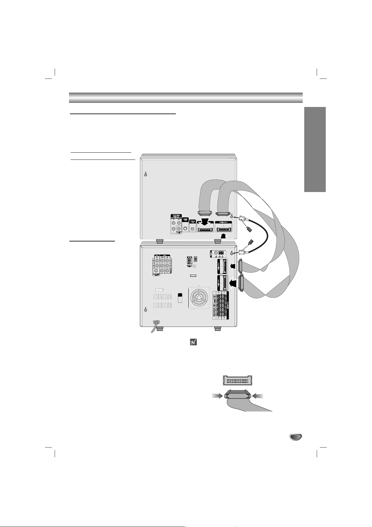
Connections
1
Stack the parts of your unit in the order shown
above.
Position your unit so that you have easy access to
the rear of it.
22
Connect the SYSTEM JACK1 on the Cassette
tape player/DVD/KARAOKE Player to the
SYSTEM JACK1 connector on the Tuner/
Amplifier.
33
Connect the SYSTEM JACK2 connector on the
Cassette tape player/DVD/KARAOKE Player
player to the SYSTEM JACK2 connector on the
tuner/ Amplifier.
4
Connect the LUG cable to the LUG connector
on the unit with the supplied hand screw.
otes
The system connection cables will only connect and should
‘click’ into place, do not try to force them.
If you need to unplug the system connection cables,
squeeze both sides of each plug before pulling it out - this
will ‘unlock’ the plug and allow it to be released.
Cassette tape player/
DVD/KARAOKE Player
Tuner/ Amplifier
Fitting the system connection cables
• Your unit consists of two separate parts, Cassette tape player/DVD/KARAOKE player and an integrated Tuner/
Amplifier.
• Before you can use your unit, the separate parts must be connected with the supplied system connection cables.
• Make sure that all connections are made with your unit unplugged from the mains supply.
Connections
8
Make one of the following connections, depending on
the capabilities of your existing equipment.
ips
Depending on your TV and other equipment you wish
to connect, there are various ways you could connect
the
unit
. Use one of the connections described
below.
Please refer to the manuals of your TV, VCR, Stereo
System or other devices as necessary to make the
best connections.
Caution
–
Make sure the unit is connected directly to the TV.
Select the correct AV input on your TV.
– Do not connect your
unit
to TV via your VCR. The
DVD image could be distorted by the copy protection
system.
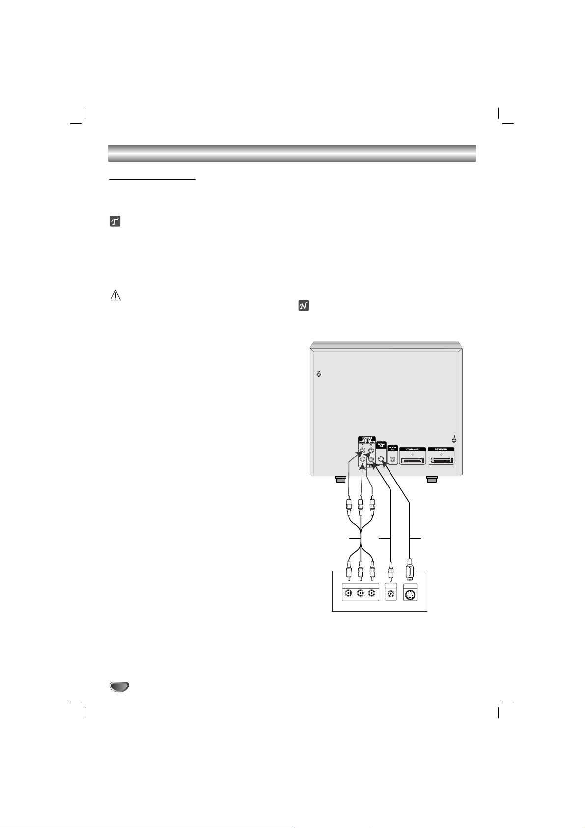
Video connection
Connect the MONITOR OUT jack from the
unit
to the
VIDEO IN jack on the TV using the video cable supplied
(V).
S-Video connection
Connect the S-VIDEO OUT jack on the
unit
to the S-
VIDEO IN jack on the TV using the S-Video cable (S).
Component Video (Color Stream®) connection
Connect the COMPONENT VIDEO (PROGRESSIVE
SCAN) jacks from the
unit
to the corresponding in jacks
on the TV using an Y Pb Pr cable (C).
Progressive Scan (ColorStream®pro) connection
If your television is a high-definition or “digital ready”
television, you may take advantage of the
unit
’s progressive scan output for the highest video resolution
possible.
If your TV does not accept the Progressive Scan format, the picture will appear scrambled if you try
Progressive Scan on the
unit
.
Connect the COMPONENT VIDEO OUT (PROGRESSIVE
SCAN) jacks from the
unit
to the corresponding in jacks
on the TV using an optional Y Pb Pr cable (C).
ote
– Set the Progressive to “On” on the Setup menu for
progressive signal, see page 17.
Connecting to a TV
C
COMPONENT VIDEO /
PROGRESSIVE SCAN INPUT
Y
Pr
Rear of TV
S-VIDEO
S
IN
V
VIDEO
IN
Pb
L
9
PREPARATION
Connections
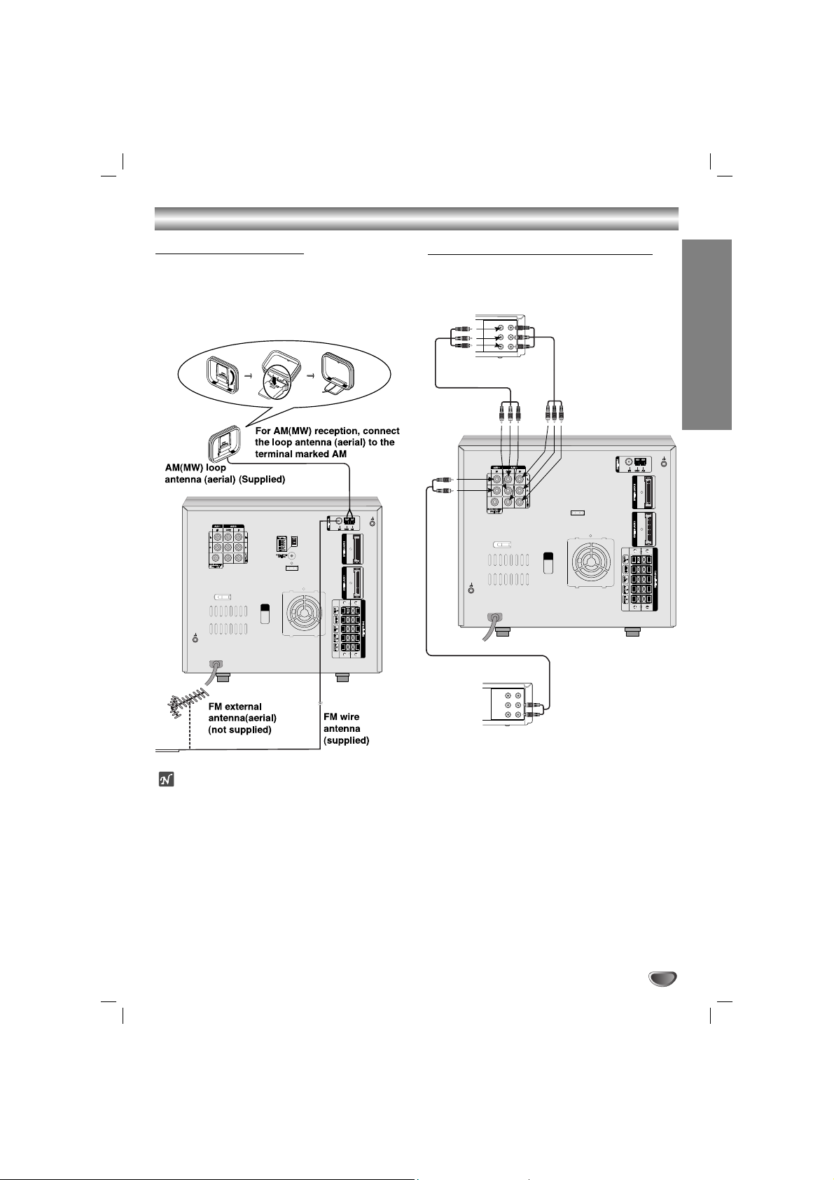
Connecting to Antenna
Connect the supplied FM/AM antennas for listening to
the radio.
- Connect the AM loop antenna to the AM antenna
connector.
- Connect the FM wire antenna to the FM antenna
connector.
otes
To prevent noise pickup, keep the AM loop antenna
away from the unit and other component.
Be sure to fully extend the FM wire antenna.
After connecting the FM wire antenna, keep it as
horizontal as possible.
Connecting to Auxiliary Equipment
You can use VCR or other unit connected to the AUX1,
AUX2 connector.
VIDEO
OUTIN
AUDIO (L)
AUDIO (R)
VIDEO
OUTIN
AUDIO (L)
AUDIO (R)
VCR (or Auxiliary Device, etc)
Additional VCR
(or Auxiliary Device, etc)
To AUDIO IN
To AUDIO OUT
To AUDIO/
VIDEO IN
To AUDIO/
VIDEO OUT
To AUDIO/
VIDEO IN
To AUDIO/
VIDEO OUT
1
Connect a VCR or auxiliary device, etc to the AUX
1 connector.
22
Connect a additional VCR or auxiliary device, etc
to the AUX 2 connector.
33
Select AUX1 or AUX2 pressing the AUX button on
the Tuner/ Amplifier or the AUX1/2 button on the
remote control.
Connections
10
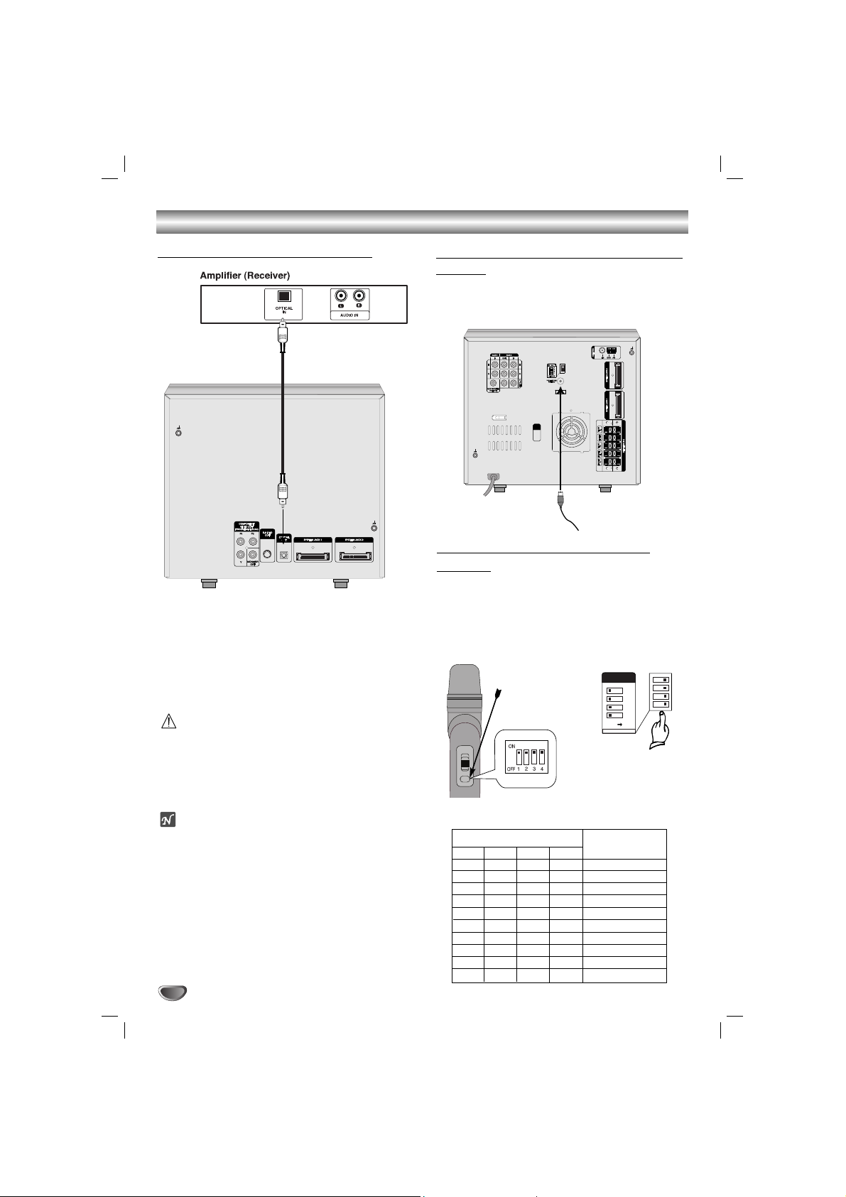
Connecting to Optional Equipment
[Connecting to an amplifier equipped with two
channel digital stereo (PCM) or to an Audio/
Video receiver equipped with a multi-channel
decoder (Dolby Digital™, MPEG 2 or DTS)
C
onnect the OPTICAL OUT jack on
the unit
to the
OPTICAL IN jack on your amplifier. Use an optional
audio cable.
Caution:
Due to the DTS Licensing agreement, the digital output
will be in DTS digital out when DTS audio stream is
selected.
The sound is muted during playback on an audio CD
recorded in dts.
Notes
– If the audio format of the digital output does not
match the capabilities of your unit, the DVD Karaoke
will produce a strong, distorted sound or no sound at
all.
– Six Channel Digital Surround Sound via digital con-
nection can only be obtained if your unit is equipped
with a Digital Multi-channel decoder.
– To see the audio format of the current unit in the On-
Screen Display, press AUDIO.
Connecting to the Wireless microphone
antenna
When you use the wireless microphone, connect the
supplied wireless microphone antenna to the wireless
microphone antenna jack of the unit.
Wireless microphone
antenna
Setting the Wireless microphone
Channel
If there is a similar wireless microphone product
nearby, interference may occur. In this case, change
the channel switch to other channel, and turn off the
power, then turn on again.
By using the Channel Switch, set the same channel.
You can set the channel change with 10 types.
CHANNEL
4
3
2
1
OFF ON
[Rear panel of the unit]
ON
[Wireless microphone]
Open the cover.
1
ON
OFF
ON
OFF
ON
OFF
ON
OFF
ON
OFF
2
OFF
ON
ON
OFF
OFF
ON
ON
OFF
OFF
ON
3
OFF
OFF
OFF
ON
ON
ON
ON
OFF
OFF
OFF
4
OFF
OFF
OFF
OFF
OFF
OFF
OFF
ON
ON
ON
CH1
CH2
CH3
CH4
CH5
CH6
CH7
CH8
CH9
CH10
Channel switch number
Channel number
PREPARATION
11
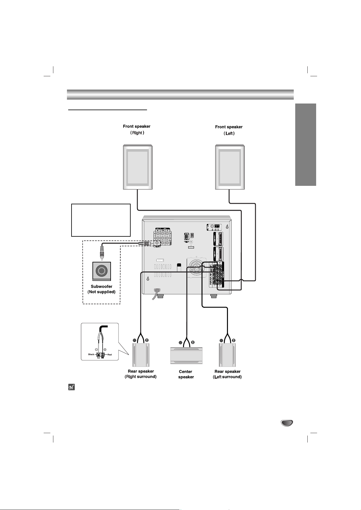
Connections
otes
Be sure to match the speaker cord to the appropriate terminal on the components: + to + and – to –. If the cords
are reversed, the sound will be distorted and will lack base.
If you use front speakers with low maximum input rating, adjust the volume carefully to avoid excessive output
on the speakers.
Speaker System Connection
Connect the speakers using the supplied speaker cords by matching the colors of the terminals and those of the
cords. To obtain the best possible surround sound, adjust the speaker parameters (distance, level, etc.).
If you feel lack of bass
frequency
Connect an active sub woofer
to the SUB WOOFER OUT
connector using a monaural
audio cord (not supplied).
 Loading...