


P/NO : 3828A20567R
www.lg.com
INSTALLATION MANUAL
AIR CONDITIONER
• Please read this installation manual completely before installing the product.
• Installation work must be performed in accordance with the national wiring
standards by authorized personnel only.
• Please retain this installation manual for future reference after reading it
thoroughly.
TYPE : MULTI
ENGLISH
ESPAÑOL
PORTUGUÊS

2 Air Conditioner
Air Conditioner Installation Manual
TABLE OF CONTENTS
Installation Requirements
Required Tools
Installation Parts Provided.........................................3
Safety Precautions......................................................4
Installation of indoor, outdoor unit .....................7~28
Flaring Work and Connection of Piping ...........29~31
Connecting the Cable between Indoor Unit and
Outdoor Unit........................................................32~33
Checking the Drainage, Forming the Pipings and
Long Pipe Setting................................................34~35
Air Purging and Evacuation...............................36~37
Test Running..............................................................38
Optional Operation - Duct Types.......................39~42
Combination indoor units ........................................43
Installation guide at the seaside..............................44
o Level gauge
o Screw driver
o Electric drill
o Hole core drill (ø50mm)
o Horizontal meter
o Flaring tool set
o Specified torque wrenches
1.8kg.m, 4.2kg.m, 5.5kg.m, 6.6kg.m
(different depending on model No.)
o Spanner .................Half union
o A glass of water
o Screw driver
o Hexagonal wrench(4mm)
o Gas-leak detector
o Vacuum pump
o Gauge manifold
o Owner's manual
o Thermometer
o Holder Remote Control
Installation Parts Provided
Installation Manual 3
ENGLISH
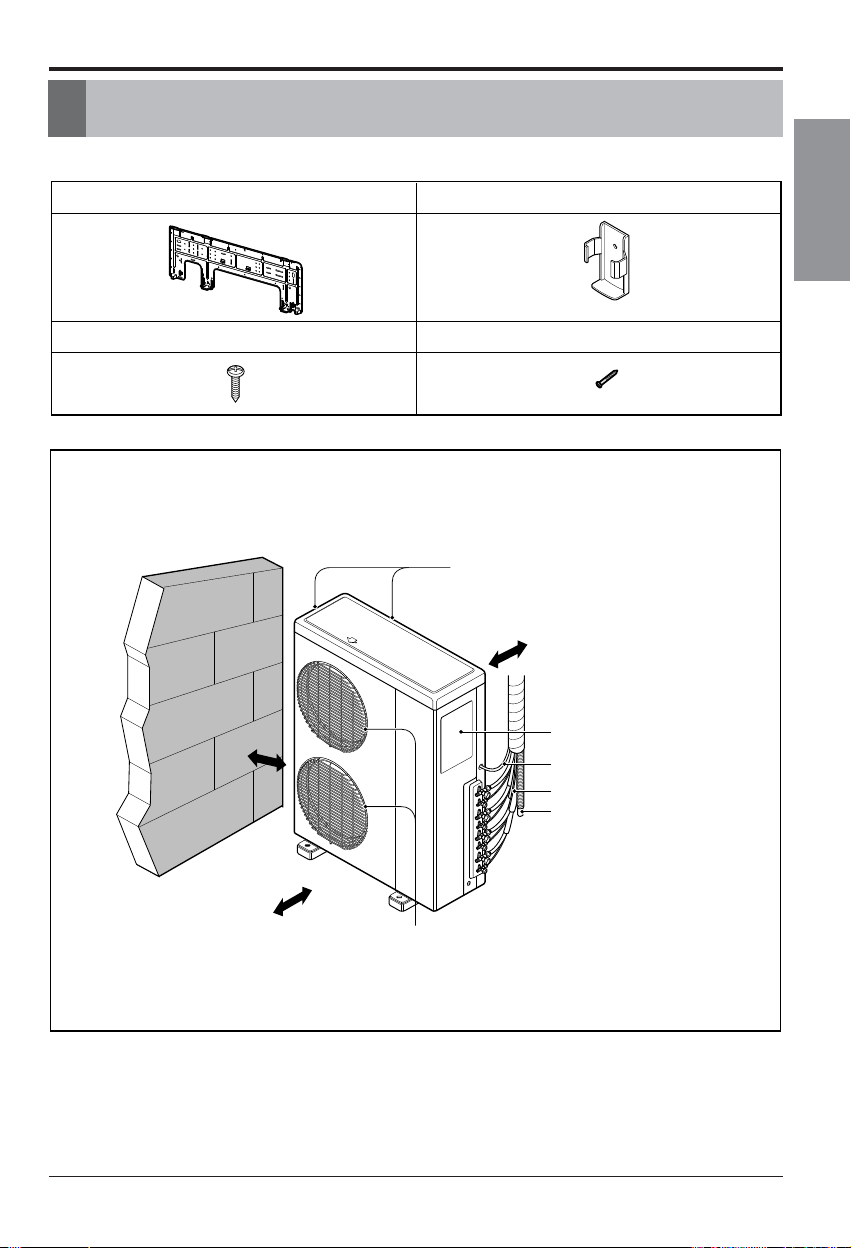
Installation Parts Provided
Outdoor Unit
Wall Mounted Type
Installation plate
Type "B" screws (2EA)
Type "A" screw (8 EA)
Holder Remote Control
more than
700
more than
300
more than
300
Air Outlet
Air Intake
(side, rear)
Connection pipe
Drain hose
Connecting wire
Control cover
more than
300
(unit : mm)
4 Air Conditioner
Safety Precautions
To prevent injury to the user or other people and property damage, the following instructions
must be followed.
n Incorrect operation due to ignoring instruction will cause harm or damage. The seriousness
is classified by the following indications.
n Meanings of symbols used in this manual are as shown below.
WARNING
CAUTION
This symbol indicates the possibility of death or serious injury.
This symbol indicates the possibility of injury or damage.
Be sure not to do.
Be sure to follow the instruction.
Safety Precautions
WARNING
n Installation
Install the panel and the cover of
control box securely.
• There is risk of fire or
electric shock.
Always install a dedicated
circuit and breaker.
• Improper wiring or
installation may cause fire or
electric shock
Use the correctly rated breaker
or fuse.
• There is risk of fire or
electric shock.
Do not use a defective or
underrated circuit breaker. Use
this appliance on a dedicated
circuit.
• There is risk of fire or
electric shock.
For electrical work, contact the
dealer, seller, a qualified
electrician, or an Authorized
Service Center.
•
Do not disassemble or repair
the product. There is risk of
fire or electric shock.
Always ground the product.
• There is risk of fire or
electric shock.

ENGLISH
Installation Manual 5
Safety Precautions
Do not modify or extend the power cable.
• There is risk of fire or electric shock.
Be cautious when unpacking and installing the
product.
•
Sharp edges could cause injury. Be especially
careful of the case edges and the fins on the
condenser and evaporator.
For installation, always contact the dealer or an
Authorized Service Center.
• There is risk of fire, electric shock, explosion,
or injury.
Do not install the product on a defective
installation stand.
• It may cause injury, accident,
or damage to the product.
Be sure the installation area does not
deteriorate with age.
•
If the base collapses, the air conditioner could fall with
it, causing property damage, product failure, and
personal injury.
Do not let the air conditioner run for a long time when
the humidity is very high and a door or a window is
left open.
• Moisture may condense and wet or damage
furniture.
Do not store or use flammable gas or combustibles near the product.
• There is risk of fire or failure of product.
Use a vacuum pump or Inert (nitrogen) gas when
doing leakage test or air purge. Do not compress air
or Oxygen and Do not use Flammable gases.
Otherwise, it may cause fire or explosion.
• There is the risk of death, injury, fire or
explosion.
n Operation
6 Air Conditioner
Safety Precautions
Always check for gas (refrigerant) leakage after
installation or repair of product.
• Low refrigerant levels may cause failure of
product.
Install the drain hose to ensure that water is
drained away properly.
• A bad connection may cause water leakage.
Keep level even when installing the product.
• To avoid vibration or water leakage.
Do not install the product where the noise or hot air
from the outdoor unit could damage the
neighborhoods.
• It may cause a problem for your neighbors.
Don't let people to lift and transport the
product. (Use fork lift)
• Avoid personal injury.
Do not install the product where it will be
exposed to sea wind (salt spray) directly.
• It may cause corrosion on the product.
Corrosion, particularly on the condenser and
evaporator fins, could cause product
malfunction or inefficient operation.
CAUTION
n Installation
Installation Manual 7
ENGLISH
Installation of Indoor, Outdoor Unit
Installation of Indoor, Outdoor Unit
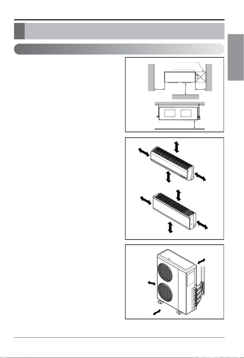
Selection of the best location
1) Indoor unit
Select location
Install the air conditioner in the location that satisfies the
following conditions.
• The place shall easily bear a load exceeding four times the
indoor unitʼs weight.
• The place shall be able to inspect the unit as the figure.
• The place where the unit shall beleveled.
• The place shall allow easy water drainage.(Suitable dimension
“H” is necessary to get a slope to drain as figure.)
• The place shall easily connect with the outdoor unit.
• The place where the unit is not affected by an electrical noise.
• The place where air circulation in the room will be good .
• There should not be any heat source or steam near the unit
• Do not have any heat or steam near the unit.
• Select a place where there are no obstacles in front of the unit.
• Make sure that condensation drainage can be conveniently
routed away.
• Do not install near a doorway.
• Ensure the spaces indicated by arrows from the wall, ceiling,
fence or other obstacles.
• Use a stud finder to locate studs to prevent unnecessary
damage to the wall.
2) Outdoor unit
• If an awning is built over the unit to prevent direct sunlight or
rain exposure, be careful that heat radiation from the
condenser is not restricted.
• There should not be any animals or plants which could be
affected by hot air discharged.
• Ensure the spaces indicated by arrows from the wall, ceiling,
fence or other obstacles.
more than
30cm
(unit : mm)
(unit : mm)
Top view
(unit: mm)
Front view
More than
100
More than 2300
More than
100
Inspection hole
(600X600)
Control box
More than 200
600600
1000
Front
H
More than
100
More than 200
More than
100
More than 2300
more than
300
more than
300
more than
700
8 Air Conditioner
Installation of Indoor, Outdoor Unit
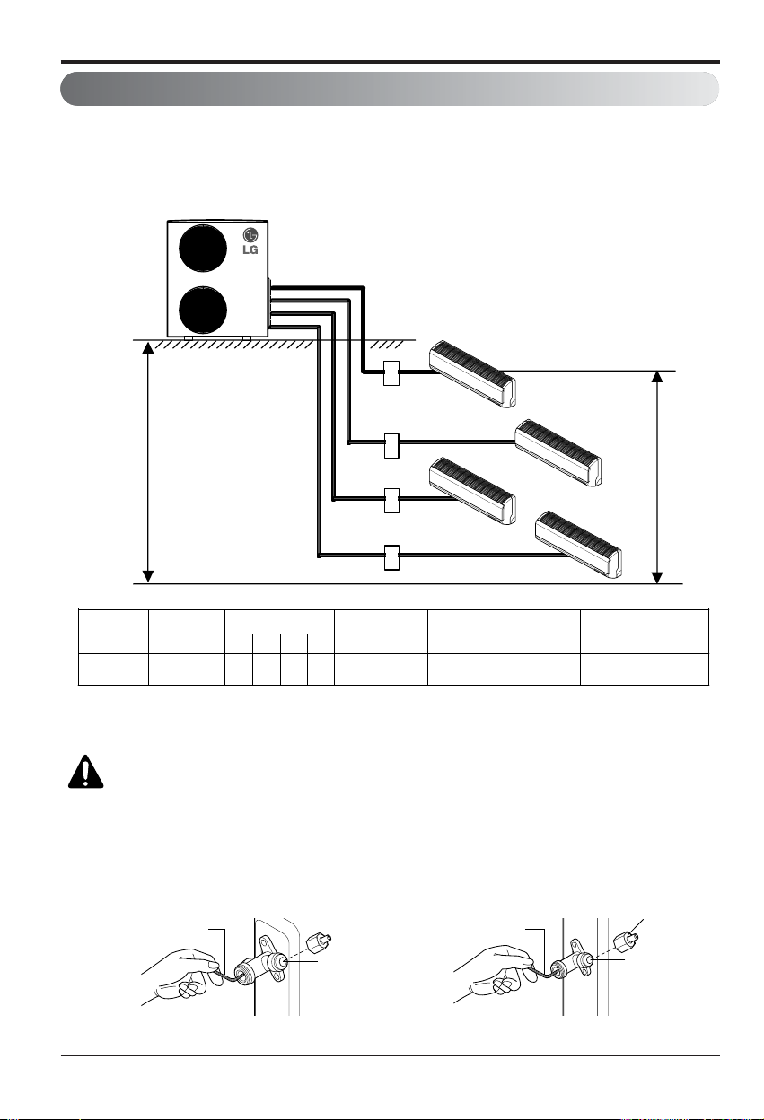
Multi Piping Type
If the number of indoor unit is below 4 in case of L4UC(H)602FA2, tighten
the valves of outdoor not connected to a indoor unit with a cap and close
the valve of outdoor not connected to a indoor unit with a service valve
wrench.
Piping length and elevation
CAUTION: Capacity is based on standard length and maximum allowance
length is on the basis of reliability. Oil trap should be installed every 5~7
meters.
It does not matter which unit is higher.
1.1 The maximun allowable level, piping length and Refrigerant Charge
15m
7.5m
A
B
C
D
[Outdoor Unit]
[Indoor Unit]
Standard Length
(m)
Max piping
(m)
L4UH602FA2
L4UC602FA2
7.5 30 30 30 30 80(A+B+C+D) 30
Model
[Outdoor Unit]
Charge(g/m)
Max total piping
length(m)
over the total 30m pipe length
Additional Charge
Gas Valve
Service Valve Wrench
Liquid Valve
Service Valve Wrench
Cap
h Extra refrigerant = (Extended length - Rated length) x Additional refrigerant
A,B,C,D A B C D
Installation Manual 9
ENGLISH
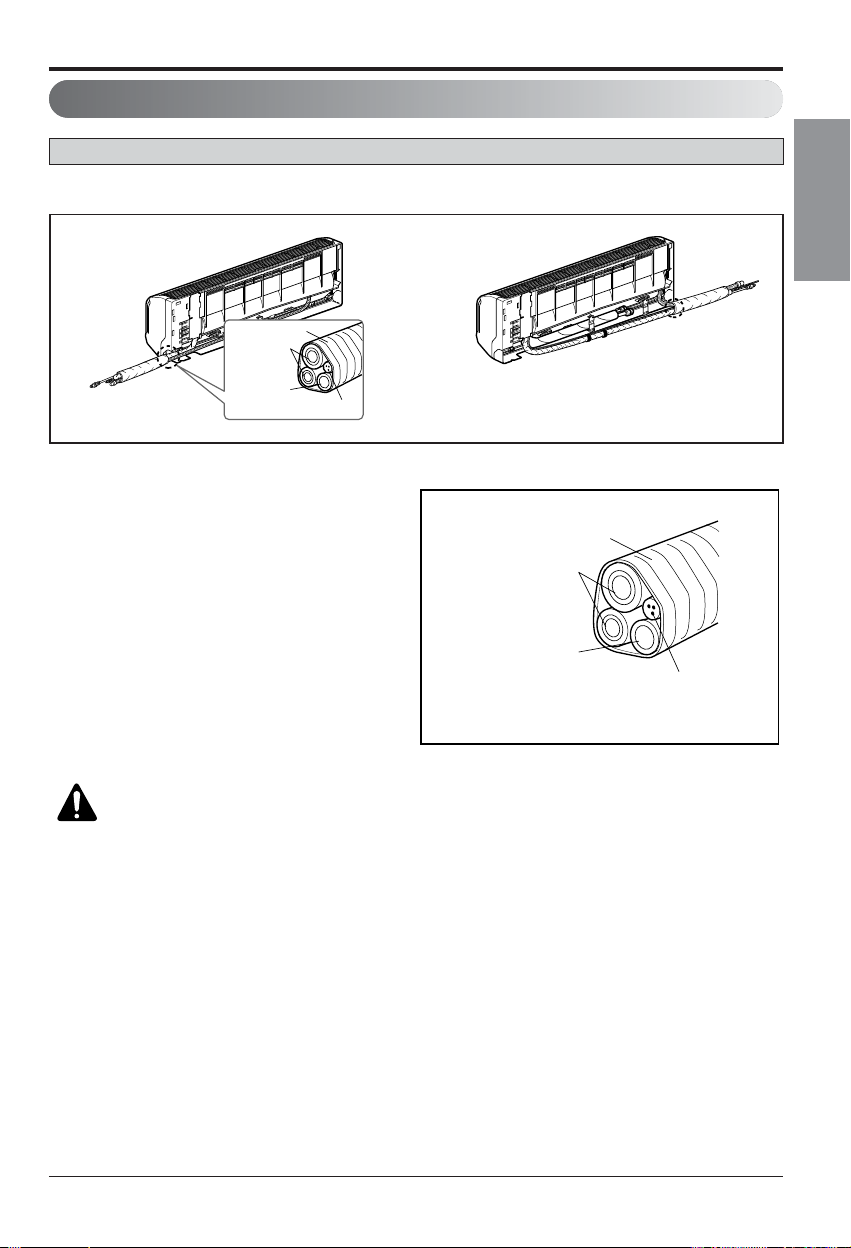
2. Tape the tubing, drain hose and the
connecting cable. Be sure that the drain hose
is located at the lowest side of the bundle.
Locating at the upper side can cause drain
pan to overflow inside the unit.
1. Route the indoor tubing and the drain hose in the direction of rear left or right
Connecting
pipe
Connecting cable
Tape
Drain hose
Connecting
pipe
Connecting cable
Tape
Drain hose
CAUTION: If the drain hose is routed inside the room, insulate the hose with
an insulation material* so that dripping from "sweating"(condensation) will
not damage furniture or floors.
*Foamed polyethylene or equivalent is recommended.
Installation of Indoor, Outdoor Unit
Indoor unit installation
Wall Mounted Type
10 Air Conditioner
Installation of Indoor, Outdoor Unit
n Indoor unit installation on
installation plate
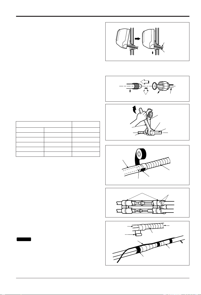
1. Hook the indoor unit onto the upper portion of
the installation plate.(Engage the two hooks
of the rear top of the indoor unit with the
upper edge of the installation plate.) Ensure
that the hooks are properly seated on the
installation plate by moving it left and right.
Press the lower left and right sides of the unit
against the installation plate until the hooks
engage into their slots(clicking sound).
Connecting the pipings to the in
door unit and drain hose to drain
pipe
1. Align the center of the pipings and sufficiently
tighten the flare nut by hand.
2. Tighten the flare nut with a wrench.
3. When extending the drain hose at the indoor
unit, install the drain pipe.
Wrap the insulation material
around the connecting portion.
1. Overlap the connection pipe insulation
material and the indoor unit pipe insulation
material. Bind them together with vinyl tape
so that there is no gap.
2. Wrap the area which accommodates the rear
piping housing section with vinyl tape.
: Recommended Insulation material
Meterial: FOAM PE
Thickness: 10mm
Density: less than 0.032 ±0.005(g/cm
3
)
Thermal conductivity: less than 0.03
(kcal/m·h°C)
NOTICE
Drain hose
Connecting
cable
Indoor unit tubing Flare nut Pipings
Torque wrench
Indoor unit tubing
Spanner (fixed)
Connection pipe
Flare nut
Vinyl tape(narrow)
Adhesive
Drain pipe
Indoor unit drain hose
Plastic bands
Insulation material
Vinyl tape(narrow)
Connection
pipe
Connecting cable
Vinyl tape
(wide)
Wrap with vinyl tape
Indoor
unit pipe
Pipe
mm inch kgf.cm
Ø6.35 1/4 180~250
Ø9.52 3.8 340~420
Ø12.7 1/2 550~560
Ø15.88 5/8 630~820
Ø19.05 3/4 990~1 210
Outside diameter Torque
Installation Manual 11
ENGLISH
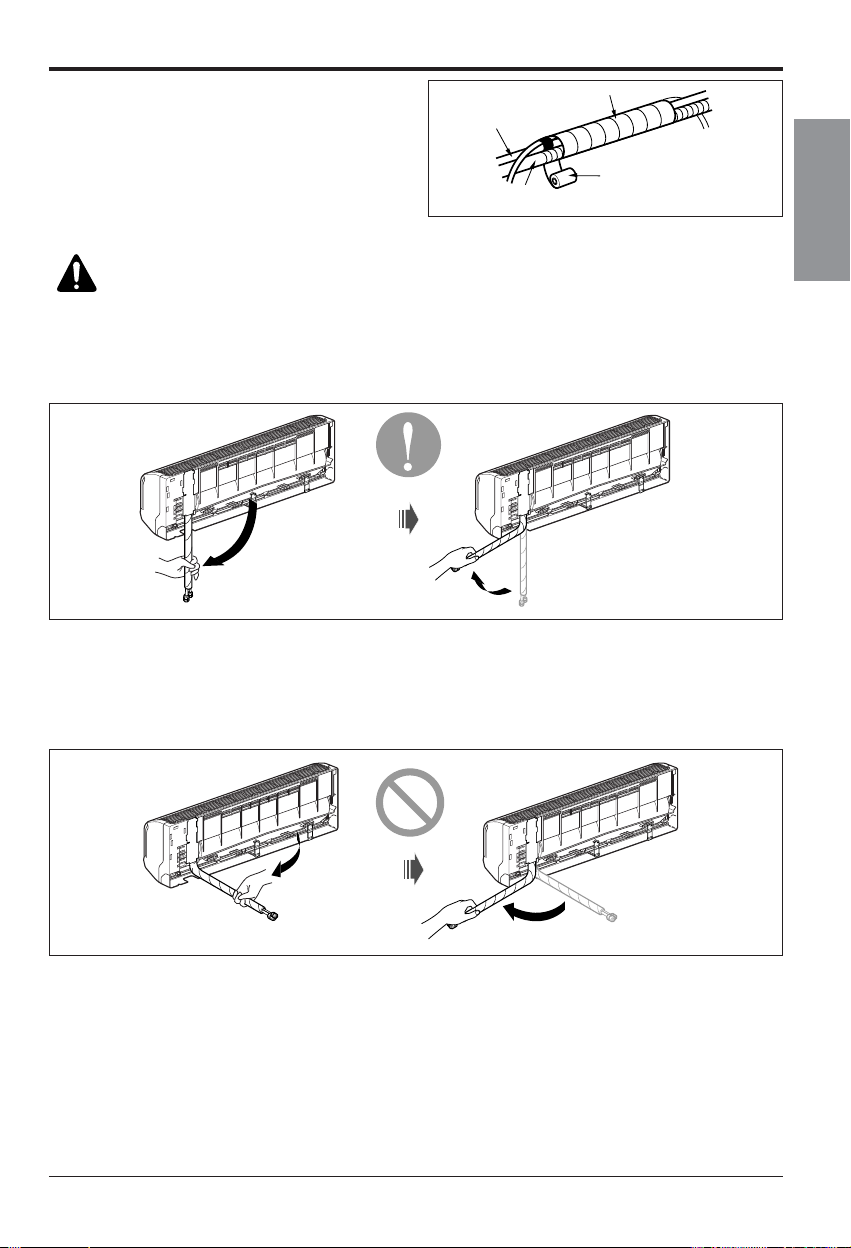
3. Bundle the piping and drain hose together by
wrapping them with vinyl tape over the range
within which they fit into the rear piping
housing section.
Good case
• Press on the upper side of clamp and unfold
the tubing to downward slowly.
Bad case
• Following bending type from left to right could
cause problem of pipe damage.
Wrap with vinyl tape
Drain hose
Pipe
Vinyl tape(wide)
CAUTION: Installation Information (For right piping)
For right piping, follow the instruction below.
Installation of Indoor, Outdoor Unit
12 Air Conditioner
Installation of Indoor, Outdoor Unit
The wall you select should be strong and
solid enough to prevent vibration
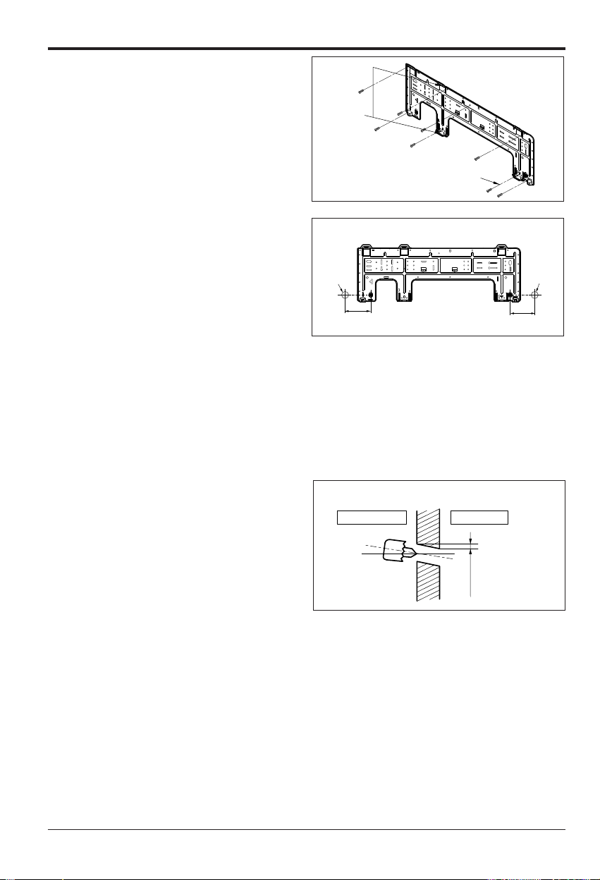
1. Mount the installation plate on the wall with
type "A" screws. If mounting the unit on a
concrete wall, use anchor bolts.
• Mount the installation plate horizontally by
aligning the centerline using a level.
2. Measure the wall and mark the centerline.
It is also important to use caution
concerning the location of the installation
plate-routing of the wiring to power outlets
is through the walls typically. Drilling the
hole through the wall for piping connections
must be done safely.
n How to fix installation plate
• Drill the piping hole with a ø70mm hole core
drill. Drill the piping hole at either the right or
the left with the hole slightly slanted to the
outdoor side.
n Drill a hole in the wall
5-7mm
(3/16"~5/16")
Indoor
WALL
Outdoor
Standard
Installation plate
Left rear piping Right rear piping
Ø70mm
133mm
Ø70mm
100mm
Chassis
Hook
Installation Plate
Type “A”
Installation Manual 13
ENGLISH
Installation of Indoor, Outdoor Unit
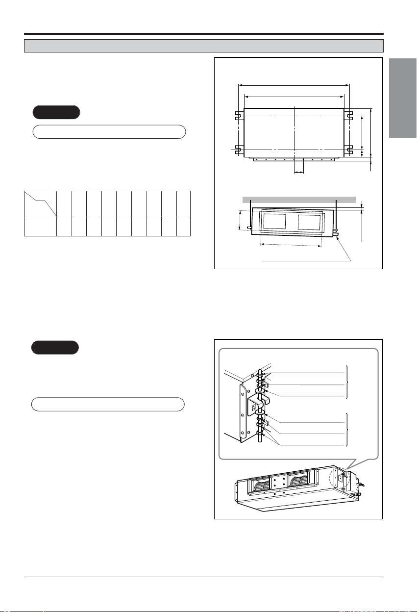
Ceiling Concealed Duct Type
n Installation of Unit
Install the unit above the ceiling correctly.
• Apply a joint-canvas between the unit and
duct to absorb unnecessary vibration.
• Apply a filter Accessory at air return hole.
• Install the unit leaning to a drainage hole
side as a figure for easy water drainage.
• A place where the unit will be leveled and
that can support the weight of the unit.
• A place where the unit can withstand its
vibration.
• A place where service can be easily
performed.
CASE 1
POSITION OF SUSPENSION BOLT
CASE 2
POSITION OF CONSOLE BOLT
(Unit:mm)
Drainage hole
A
B
C
1-3 mm
D
(G)
H
I
EF
M10 SP. washer
M10 washer
M10 Nut
X 8
X 4
(Local
supply)
X 4
M10 Nut
M10 SP. washer
M10 washer
X 4
X 4
(Local
supply)
X 8
18k
932 880 355 45.5 450 30 87 750 163
24k
Dimension
Capacity
(Btu/h)
ABCDE F(G)HI
14 Air Conditioner
Installation of Indoor, Outdoor Unit
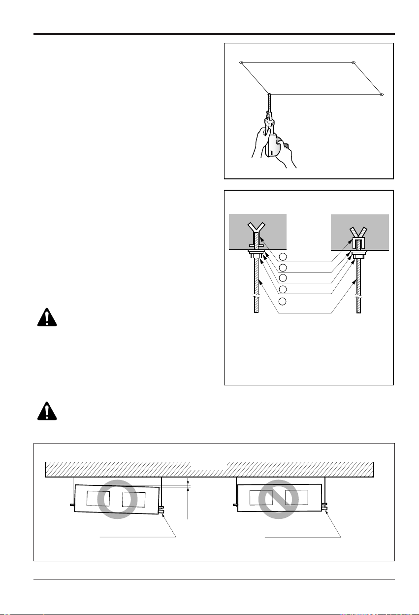
• Select and mark the position for fixing
bolts.
• Drill the hole for set anchor on the face of
ceiling.
• Insert the set anchor and washer onto the
suspension bolts for locking the suspension
bolts on the ceiling.
• Mount the suspension bolts to the set
anchor firmly.
• Secure the installation plates onto the
suspension bolts (adjust level roughly)
using nuts, washers and spring washers.
1 Set anchor
Old building New building
2 Plate washer
3 Spring washer
4 Nut
5 Suspension
bolts
• Local supply
① Set anchor
② Plate washer - M10
③ Spring washer - M10
④ Nut - W3/8 or M10
⑤ Suspension bolt - W3/8 or M10
CAUTION: Tighten the nut and
bolt to prevent unit falling
CAUTION:
1. Install declination of the indoor unit is very important for the drain of the duct type air
conditioner.
2. Minimum thickness of the insulation for the connecting pipe shall be 5mm.
Front of view
• The unit must be declined to the drain hose connected when finished installation.
CORRECT
INCORRECT
Drainage hole
Ceiling
1~3mm
Drainage hole

Installation Manual 15
ENGLISH
Installation of Indoor, Outdoor Unit
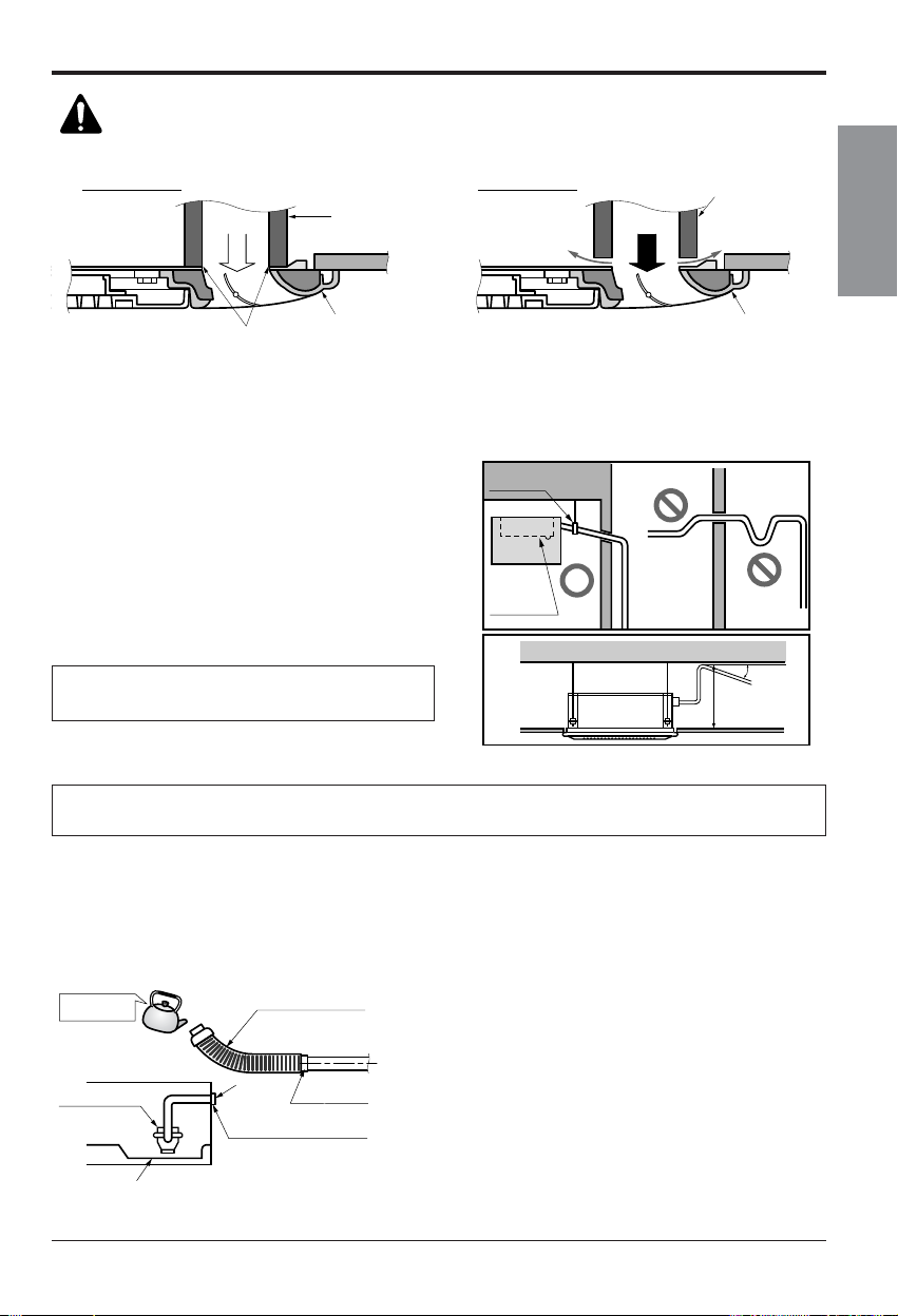
• Always lay the drain with downward
inclination (1/50 to 1/100).
Prevent any upward flow or reverse flow
in any part.
• 5mm or thicker formed thermal insulator
shall always be provided for the drain
pipe.
Lay the drain hose with a downward inclination so water will drain out.
• Install the P-Trap (or U-Trap) to prevent a
water leakage caused by the blocking of
intake air filter.
Applied U-Trap Dimension
CORRECT
INCORRECT
• Upward routing not
allowed
Caution for gradient of unit and drain piping
• Drill the piping hole with 70mm dia, hole
core drill.
• Piping hole should be slightly slant to the
outdoor side.
Unit
Make sure to be closed.
A ≥ 70mm
B ≥ 2C
C ≥ 2 x SP
SP = External Pressure
(mmAq)
Ex) External Pressure
= 10mmAq
A ≥ 70mm
B ≥ 40mm
C ≥ 20mm
Thermal insulator
(Local supply)
Drainage pipe
(Local supply)
Drainage hole
C
A
B
U-Trap
Indoor Outdoor
WALL
5~7mm

16 Air Conditioner
Installation of Indoor, Outdoor Unit
Insulate the joint and tubes completely.
All thermal insulation must comply with local requirement.
REFRIGERANT PIPE
• Insulate and tape the gas piping.
n After all workings are finished, check the working and operation.
• Air distribution Is the air circulation good?
• Drain Is the drainage smooth and no sweating?
• Gas leakage Is the piping connection correct?
• Wiring Is the wiring connection correct?
• Lock-bolt Is the lock-bolt of compressor loosened?
THERMAL INSULATION
TEST AND CHECK
Make sure that there is no clearance here.
Overlap with thermal
insulator for piping.
Thermal insulator for refrigerant pipe
(Local supply)
Thermal insulator for
piping(Local supply)
Hose clip for thermal insulator(Local supply)
Union for liquid pipe
Refrigerant pipe and thermal
insulator(Local supply)
Union for gas pipe
Thermal insulator for refrigerant pipe
(Local supply)
Hose clip for thermal insulator
(Local supply)
Power cable
Thermal insulator
Gas pipe
Liquid pipe
Tape
Insulation, others

Installation Manual 17
ENGLISH
Installation of Indoor, Outdoor Unit
Install the remote control box and cord correctly.
• Although the room temperature sensor is in the indoor unit, the remote control box should
be installed in such places away from direct sunlight and high humidity.
INSTALLATION OF THE REMOTE CONTROL BOX
• Select places that is not splashed by water.
• Select control position after receiving
customer approval.
• The room temperature sensor of the
thermostat for temperature control is built in
the indoor unit.
• This remote controller equipped with liquid
crystal display. If this position is higher or
lower, display is difficult to see.
(The standard height is 1.2~1.5m high)
ROUTING OF THE REMOTE CONTROL CORD
• Keep the remote control cord away from
the refrigerant piping and the drain piping.
• To protect the remote control cord from
electrical noise, place the cord at least 5cm
away from other power cables. (Audio
equipment, Television set, etc)
• If the remote control cord is secured to a
wall, provide a trap at the top of the cord to
prevent water droplets from running.
POINT OF REMOTE CONTROLLER INSTALLATION
DISASSEMBLING OF THE REMOTE CONTROLLER
ELECTRICAL WIRING TO THE INDOOR UNIT
Make sure that wire and terminal
numbers are matched on unit side
and remote controller side.
(Main board)
CN REMO
The maximum length of the cord is 100m.
If the length of the cord exceeds 50m, use a wire size greater than 0.5mm
2
.
Remote controller
CN REMO
Remote
control
box body
Lever carefully
the box open
using a screw
driver, etc.
Front case
The lower part
Face of wall
Upper notch
Upper flange
Under plate
Remote
control cord
Remote
control unit
Tapping screw
(Local supply)
Lower notch
Face of wall
Upper notch
Lower notch
Switch box
(Local supply)
Under plate
Remote
control unit
Remote
control cord
Screw
(Local supply)
Cord
clamp
Push hand
(Part B)
(Part A)
FIXING OF REMOTE
CONTROL CORD
1. Fix the cord clamps on the wall
by ø3 tapping screws(Local supply).
2. Fix the remote control cord.
PROCEDURE OF INSTALLATION
1. Fix the under plate on the switch box by
screws(Local supply). In this case, fit the under
plate on the wall, and be careful of deformation.
2. Receive the remote control cord in the switch
box.
3. Hook the remote control unit on the under plate.
WHEN THE REMOTE CONTROL BOX IS
INSTALLED WITH THE CORD BURIED.
PROCEDURE OF INSTALLATION
1. Fix the under plate on the wall by self tapping
screws (accessory).
2. Make a slit (Part A) at the top side of the remote
control box by nipper.
3.Rout the cord as shown in the following figure. In
this case, push the cord into the around of
case(Part B).
4. Hook the remote control unit on the under plate.
WHEN THE REMOTE CONTROL BOX IS
INSTALLED WITH THE CORD EXPOSED.
installation of remote control box

18 Air Conditioner
Installation of Indoor, Outdoor Unit
• Since the room temperature sensor is in the remote controller, the remote controller box should be installed
in a place away from direct sunlight, high humidity and direct supply of cold air to maintain proper space
temperature.
Install the remote controller about 5ft(1.5m) above the floor in an area with good air circulation at an
average temperature.
Do not install the remote controller where it can be affected by:
- Drafts, or dead spots behind doors and in corners.
- Hot or cold air from ducts.
- Radiant heat from sun or appliances.
- Concealed pipes and chimneys.
- Uncontrolled areas such as an outside wall behind the remote controller.
- This remote controller is equipped with a seven segment LED. display. For proper display of the remote
controller LED's, the remote controller should be installed properly as shown in Fig.1.
(The standard height is 1.2~1.5 m from floor level.)
Operation unit
ZONE
1234
Humidify
JET
AUTO
AUTO SWINGOPERATION
FAN SPEED
Program set
SUB FUNCTION
SET TEMP
Room Temp
HI
MED
LO
Heater
Defrost
Filter
Preheat
Out door
Time
Timer
On
Set no.Time
Off
0103 0507 0911 1315 1719 2123
O
p
era
tion
unit
Z
O
N
E
1
2
3
4
H
u
m
i
d
i
f
y
J
E
T
A
U
T
O
A
U
T
O
S
W
I
N
G
O
P
E
R
A
T
I
O
N
FA
N
S
P
E
E
D
P
rogr
am
s
et
S
U
B
F
U
N
C
T
I
O
N
S
E
T
T
E
M
P
R
o
o
m
T
e
m
p
H
I
M
E
D
L
O
H
e
a
t
e
r
D
e
f
r
o
s
t
F
i
l
t
e
r
P
r
e
h
e
a
t
O
u
t
d
o
o
r
T
im
e
T
im
e
r
O
n
S
e
t
n
o
.
T
i
m
e
O
f
f
0
1
0
3
0
5
0
7
0
9
1
1
1
3
1
5
1
7
1
9
2
1
2
3
5feet
(1.5meters)
no
no
no
yes
Operation unit
ZONE
1234
Humidify
JET
AUTO
AUTO SWINGOPERATION
FAN SPEED
Program set
SUB FUNCTION
SET TEMP
Room Temp
HI
MED
LO
Heater
Defrost
Filter
Preheat
Out door
Time
Timer
On
Set no.Time
Off
0103 0507 0911 1315 1719 2123
Fig.1 Typical locations for remote controller
• Remove the control box cover for electrical
connection between the indoor and outdoor
unit.
(Remove screws ¿.)
• Use the cord clamper to fix the cord.
WIRING CONNECTION
Control terminal board
Control box
Control box cover
(On which the Electric
Wiring Connection is put)
AA
view
Remote
control cord
Connection
cord between
the indoor unit
and the
outdoor unit
Cord clamper
1
1
Wired remote controller installation

Installation Manual 19
ENGLISH
Installation of Indoor, Outdoor Unit
Ceiling Cassette Type
• Select and mark the position for fixing bolts
and piping hole.
• Decide the position for fixing bolts slightly tilted
to the drain direction after considering the
direction of drain hose.
• Drill the hole for anchor bolt on the wall.
• The hole size for four anchor bolts is Ø14.5mm
& 40mm depth.
CAUTION
•
This air-conditioner uses a drain pump.
• Horizontly install the unit using a level
gauge.
•
During the installation, care should be
taken not to damage electric wires.
• The dimensions of the paper model for installing are the same as those of the ceiling opening dimensions.
Ceiling board
Level gauge
Ceiling
Unit:mm
744 Unit size
744 Unit size
658 (Hanging bolt)
6666
790 (Ceiling opening)
790 (Ceiling opening)
572(Hanging bolt)
109
109
Unit:mm
570 Unit size
570 Unit size
450 (Hanging bolt)
7575
600 (Ceiling opening)
600 (Ceiling opening)
521(Hanging bolt)
39.5
39.5
Unit:mm
840 Unit size
840 Unit size
672 (Hanging bolt)
101.5101.5
875 (Ceiling opening)
875 (Ceiling opening)
785 (Hanging bolt)
45
45
TE
TF
TD

20 Air Conditioner
Installation of Indoor, Outdoor Unit
Set screw of
paper model (4 pieces)
Keep the length of *( )mm between
the air conditioner bottom surface
and the ceiling surface
Paper model
for installation
Ceiling board
150mm
Adjust the same height
Ceiling board
Ceiling
Flat washer for M10
(accessory)
Keep the length of the bolt
from the bracket to 40mm
Open the ceiling board
along the outer edge of the
paper model
Flat washer for M10
(accessory)
Hanging bolt
(W3/8 or M10)
Nut
(W3/8 or M10)
Nut
(W3/8 or M10)
Spring washer
(M10)
Air Conditioner body
n The Indoor Unit Installation
2. Avoid installing air conditioner in such circumstances where cutting oil mist or iron powder is in
suspension in factories, etc.
3. Avoid places where inflammable gas is generated, flows in, is stored or vented.
4. Avoid places where sulfurous acid gas or corrosive gas is generated.
5. Avoid places near high frequency generators.
*( ) → TQ/TR : 31~34mm
TP/TN/TM : 15mm
• Thoroughly study the following installation locations:
1. In such places as restaurants and kitchens, considerable amount of oil steam and flour
adhere to the turbo fan, the fin of the heat exchanger and the drain pump, resulting in heat
exchange reduction, spraying, dispersing of water drops, drain pump malfunction, etc.
In these cases, take the following actions:
• Make sure that the ventilation fan for smoke-collecting hood on a cooking table has sufficient
capacity so that it draws oily steam which should not flow into the suction of the air
conditioner.
• Make enough distance from a cooking room to install the air conditioner in such a place
where it may not suck in oily steam.
NOTICE
Use the ventilation fan
for smoke-collecting
hood with sufficient
capacity.
Cooking table
Air conditioner
Take enough
distance

Installation of Indoor, Outdoor Unit
Installation Manual 21
ENGLISH
n Remote Controller Installation
• The following parts is option.
① Hanging Bolt - W 3/8 or M10
② Nut - W 3/8 or M10
③ Spring Washer - M10
④ Plate Washer - M10
CAUTION
Tighten the nut and bolt to prevent
unit falling.
• Drill the piping hole on the wall slightly tilted to the
outdoor side using a Ø 70 hole-core drill.
• Although the room temperature sensor is in the indoor unit, the remote controller should
be installed in such places away from direct sunlight and high humidity.
Installation of the remote controller
• Select places that are not splashed with water.
• Select control position after receiving customer approval.
• The room temperature sensor is built in the indoor unit.
• This remote controller equipped with liquid crystal display. If this position is higher or lower,
display is difficult to see.(The standard height is 1.2 ~ 1.5m high)
Routing of the remote controller cord
• Keep the remote controller cord away from the refrigerant piping and the drain piping.
• To protect the remote controller cord from electrical noise, place the cord at least 5cm away
from other power cables (audio equipment, television set, etc.)
• If the remote controller cord is secured to the wall, provide a trap at the top of the cord to
prevent water droplets from running.
Wall
5~7mm
Indoor Outdoor

22 Air Conditioner
Installation of Indoor, Outdoor Unit
n WIRED REMOTE CONTROL INSTALLATION (ACCESSARY)
1. Disassemble the remote controller from
the installation board.
•
Use the driver as shown in the right picture
and insert it into the hole with the arrow. And
then you pull the driver in the front direction,
the remote controller will be separated.
2. Connect the remote controller cable to
the wired remote controller installation
board as shown in the right picture.
3. After fixing the cable to the guide slot,
attach the wired remote controller
installation board at the desired location.
• Before fixing the remote controller cable to
the guide slot, remove any clogged part of
the case in the direction to install before the
installation.
4. After locating the wired remote
controller installation board at the
desired location, screw the unit firmly.
(When there is a buried box, install the
wired remote controller board to fit the
buried box.)
• Use the screw provided.
5. After fixing the top part of the remote
controller to the installation board as
shown in beside picture, press the
bottom part to assemble the controller
to itʼs board.
12V Red wire
SIG Yellow wire
GND Black wire
j The remote controller cable is connected as factory default.
12V SIG GND
Red
Yellow
Black
Remote Controller
Cable
Guide slot
Fixate the remote
controller cable
to the guide slot.
Use the screws
for fixate the unit
firmly on the wall.
Installation board
<Front side of
installation board>
<Rear side of
installation board>
Top
Bottom
Wall
Side
Wall
Side
Wall
Side

Installation of Indoor, Outdoor Unit
Installation Manual 23
ENGLISH
HOW TO MOUNT ONTO A WALL
HOW TO INSERT BATTERIES
Remove the battery cover from the remote
controller.
• Slide the cover according to the arrow
direction.
Insert the two batteries.
• Be sure that the (+) and (-) directions are
correct.
• Be sure that both batteries are new.
Re-attach the cover.
• Slide it back into position.
n Remote Control Preparation
• Do not use rechargeable
batteries, such batteries differ
from standard dry cells in
shape, dimensions, and
performance.
• Romove the batteries from
the remote controller if the air
conditioner is not going to be
used for some long time.
6. Use the connecting cable to connect the indoor unit and the remote controller.
7. When the distance between the wired remote controller and the indoor unit is 10m
and above, use the extension cable.
When installing the wired remote controller, do not bury it in the wall.
(It can cause damage in the temperature sensor.)
Do not install the cable to be 50m or above.
(It can cause communication error.)
• When installing the extension cable, check the connecting direction of the connector of the remote
controller side and the product side for correct installation.
• If you install the extension cable in the opposite direction, the connector will not be connected.
• Specification of extension cable: 2547 1007 22# 2 core 3 shield 5 or above.
CAUTION
Check whether the connector
is connected correctly.
Connecting cable
Indoor
unit side

24 Air Conditioner
Installation of Indoor, Outdoor Unit
n Wiring Connection
•
Open the control box cover and connect the Remote controller cord and Indoor power wires.
Remote Controller
Cable
Connecting
Cable
LN
Indoor unit Outdoor unit
3 LN3

Installation of Indoor, Outdoor Unit
Installation Manual 25
ENGLISH
n Installation of Decorative Panel
The decorative panel has its installation direction.
Before installing the decorative panel, always remove the paper template.
1. Remove the packing and take out air inlet
grille from front panel.
2. Remove the Corner covers of the panel.
3. Fit the panel on the unit by inserting
hooks as shown in picture.
4. Insert two screws on diagonal corners of
panel. Do not tighten the bolts
completely. (The fixing screws are
included in the indoor unit box.)
Check the alignment of panel with the
ceiling. Height can be adjusted using
hanging bolts as shown in picture. Insert
the other two screws and tighten all
screws completely.
Inlet grille
Corner cover
Hook clip
Hook

26 Air Conditioner
Installation of Indoor, Outdoor Unit
5. Fit the corner covers.
6. Open two screws of control panel cover.
7. Connect one display connector and two
vane control connectors of front panel to
indoor unit PCB.
The position marking on PCB is as:
Display connector : CN-DISP
Vane control connector: CN-VANE 1,2
8. Close the cover for control box.
9. Fit the link on the panel as shown in
picture. (The link is included in the front
panel unit box.)
10. Attach the other side of link on the filter
guide of inlet grille. Install the air inlet
grille and filter on the panel.
Screw
Link
Link
Filter
guide
CN VANE 1,2
CN DISP
Installation of Indoor, Outdoor Unit
Installation Manual 27
ENGLISH
CAUTION
Install certainly the decorative panel.
Cool air leakage causes sweating. Water drops fall.
• Drain piping must have down-slope (1/50 to
1/100): be sure not to provide up-and-down
slope to prevent reversal flow.
• During drain piping connection, be careful
not to exert extra force on the drain port on
the indoor unit.
• The outside diameter of the drain
connection on the indoor unit is 32mm.
• Be sure to execute heat insulation on the
drain piping.
DRAIN TEST
The air conditioner uses a drain pump to drain water.
Use the following procedure to test the drain pump operation:
• Connect the main drain pipe to the exterior and leave
it provisionally until the test comes to an end.
• Feed water to the flexible drain hose and check the
piping for leakage.
• Be sure to check the drain pump for normal
operating and noise when electrical wiring is
complete.
• When the test is complete, connect the flexible drain
hose to the drain port on the indoor unit.
Air conditioner
unit
Ceiling
board
Decorative panel
Decorative
panel
Fit the insulator (this part) and
be careful for cool air leakage
Good example
Air
Cool air leakage
(no good)
Bad example
Ceiling
board
Air conditioner unit
Maintenance
drain port
Upward
routing
not allowed
Pipe clamp
Indoor unit
1/50~1/100
MAX 700mm
Piping material: Polyvinyl chloride pipe VP-25
and pipe fittings
Heat insulation material: Polyethylene foam with thickness more than 10 mm.
n Indoor Unit Drain Piping
Feed water
Drain Pump
Drain pan
Flexible drain hose
(accessory)
Main
drain pipe
Glue the joint
Drain
port
Drain hose connection
Use the clip (accessory)

28 Air Conditioner
Installation of Indoor, Outdoor Unit
HEAT INSULATION
1. Use the heat insulation material for the refrigerant piping which has an excellent heatresistance (over 120°C).
2. Precautions in high humidity
circumstance:
This air conditioner has been tested
according to the "ARI Standard"
Conditions with Mist" and confirmed
that there is not any default. However, if
it is operated for a long time in high
humid atmosphere (dew point
temperature: more than 23°C), water
drops are liable to fall. In this case, add
heat insulation material according to the
following procedure:
•
Heat insulation material to be prepared... Adiabatic EPDM or NBR with thickness 10 to 20mm.
• Stick EPDM or NBR on all air conditioners that are located in ceiling atmosphere.
• In addition to the normal heat insulation (thickness: more than 10mm) for refrigerant piping
(gas piping: thick piping) and drain piping, add further 10mm to 30mm thickness material.
Indoor unit
Thermal insulator
(accessory)
Fastening band
(accessory)
Refrigerant piping
1/50~1/100
MAX 800mm
Flexible drain hoseFlexible drain hoseFlexible drain hose
CAUTION
The supplied flexible drain hose
should not be curved, neither
screwed. The curved or screwed
hose may cause a leakage of water.

Flaring Work and Connection of Piping
Installation Manual 29
ENGLISH
Flaring Work and Connection of Piping
Flaring work
Preparation of Piping
Main cause of gas leakage is defect in flaring
work. Carry out correct flaring work in the
following procedure.
1. Cut the pipes and the cable.
• Use the accessory piping kit or the pipes
purchased locally.
• Measure the distance between the indoor
and the outdoor unit.
• Cut the pipes a little longer than measured
distance.
•
Cut the cable 1.5m longer than the pipe
length.
2. Burrs removal
• Completely remove all burrs from the cut
cross section of pipe/tube.
•
Put the end of the copper tube/pipe to
downward direction as you remove burrs in
order to avoid to let burrs drop in the tubing.
3. Putting nut on
• Remove flare nuts attached to indoor and
outdoor units, than put them on pipe/tube
having completed burr removal.
(Not possible to put them on after flaring work)
4. Flaring work
•
Carry out flaring work using dedicated
flaring tool for R-22 as shown below.
Firmly hold copper tube in a bar(or die) as
indicated dimension in the table above.
Copper
tube
90°
Slanted Uneven Rough
Pipe
Reamer
Point down
Flare nut
Copper tube
Bar
Copper pipe
Clamp handle
Red arrow mark
Cone
Yoke
Handle
Bar
"A"
Outside diameter A
mm inch mm
Ø6.35 1/4 1.1~1.3
Ø9.52 3/8 1.5~1.7
Ø12.7 1/2 1.6~1.8
Ø15.88 5/8 1.6~1.8
Ø19.05 3/4 1.9~2.1

30 Air Conditioner
Flaring Work and Connection of Piping
5. Check
• Compare the flared work with figure below.
• If flare is noted to be defective, cut off the
flared section and do flaring work again.
Inclined
Inside is shining without scratches
Smooth all round
Even length
all round
Surface
damaged
Cracked Uneven
thickness
= Improper flaring =
1. Form the piping according to its routing.
Avoid bending and bending back the same
piping point more than three times. (This will
result in hardening the pipe.)
2. After deforming the piping, align centers of
the union fitting of the indoor unit and the
piping, and tighten them firmly with
wrenches.
3.
Connect pipe to the service valve, ball valve
or short tube(only 48 kBtu/h) which is located.
4. After completing the piping connection, be
sure to check if there is gas leakage in indoor
and outdoor connection.
Vacuum drying
After completing the piping connection, execute
vacuum drying for the connecting piping and
the indoor unit.
The vacuum drying must be carried out using
the service ports of both the liquid and gas side
valves.
Connection of the pipes-Outdoor
1. When piping installation work you must be
used the connector.
Connecting pipe size
Outdoor
unit
Short tube
(48k)
Liquid side
Flare connection
Flare connection
Gas side
Indoor
unit
A
B
Gas
AB
24k
Ø12.7(1/2) Ø15.88(5/8)
Capacity
(Btu/h)
Capacity(Btu/h)
Gas side Liquid side
12/18k Ø12.7(1/2) Ø6.35(1/4)
24k
Ø15.88(5/8) Ø6.35(1/4)
Piping Connection
unit : mm(inch)
unit : mm(inch)

Installation Manual 31
ENGLISH
Flaring Work and Connection of Piping
Align the center of the piping and sufficiently
tighten the flare nut by hand.
When tightening side piping, tighten below.
1st, tighten gas side piping of A
2nd, tighten liquid side piping of A
3rd, tighten gas side piping of B
4th, tighten liquid side piping of B
5th, tighten gas side piping of C
6th, tighten liquid side piping of C
7th, tighten gas side piping of D
8th, tighten liquid side piping of D
Finally, tighten the flare nut with torque wrench
until the wrench clicks.
• When tightening the flare nut with torque
wrench ensure the direction for tightening
follows the arrow on the wrench.
Liquid side
piping
Outdoor unit
Gas side
piping
Torque
wrench
A
B
C
D
Outside diameter Torque
mm inch kg.m
Ø6.35 1/4 1.8
Ø9.52 3/8 4.2
Ø12.7 1/2 5.5

32 Air Conditioner
Connecting the Cable between Indoor Unit and Outdoor Unit
Connecting the Cable between Indoor Unit and Outdoor Unit
Connect the cable to the indoor unit by connecting the wires to the terminals on the control
board individually according to the outdoor unit connection. (Ensure that the color of the wires
of the outdoor unit and the terminal No. are the same as those of the indoor unit.)
The earth wire should be longer than the common wires.
The circuit diagram is not subject to change without notice.
When installing, refer to the circuit diagram behind the panel front of Indoor Unit the wiring
diagram on the Control Cover Inside Outdoor Unit.
Connect the cable to the Indoor unit.
CAUTION:
• The circuit diagram is not subject to change without notice.
• Be sure to connect wires according to the wiring diagram.
• Connect the wires firmly, so that not to be pulled out easily.
• Connect the wires according to color codes by referring the wiring diagram.
CAUTION: Provide a circuit
breaker between power source
and the unit as shown below.
CAUTION:
The power cord connected to the outdoor unit should be complied
with the following specifications (Cable type approved by HAR or SAA).
The power connecting cable connected to the indoor and outdoor unit
should be complied with the following specifications (Type "B" approved by
HAR or SAA).
Air
Conditioner
Main power source
Circuit Breaker
Use a circuit breaker
or time delay fuse.
GN/YL
20mm
60k
6
Cable Type
H07RN-F
NORMAL CROSS
SECTIONAL AREA
Grade
(mm2)
NORMAL
CROSS-SECTIONAL
AREA 0.75mm
2
H07RN-F
ø7.5mm
GN/YL
20mm

Installation Manual 33
ENGLISH
Connecting the Cable between Indoor Unit and Outdoor Unit
Connect the cable to the Outdoor unit
1. Open the side panel cover from the outdoor
unit by removing the screws.
2. Connect wires to the terminals on the control
board individually and secure the cables onto
the control board with clamp.
3. Secure the control board cover to the original
position with the screws.
4. Use a recongnized circuit breaker between
the power source and the unit. A
disconnection device to adequately
disconnect all supply lines must be fitted.
Outdoor unit
CAUTION: After the confirmation of the above conditions, prepare the wiring
as follows.
1. Never fail to have an individual power circuit specifically for the air conditioner. As
for the method of wiring, be guided by the circuit diagram posted on the inside of
control cover.
2. Firmly tighten the terminal screws to prevent them loosening. After tightening, pull
the wires lightly to confirm that they do not move. (If they are loose the unit, the unit
will not operate normally or it can cause burn-out of the wires.)
3. Specification of power source.
4. Confirm that electrical capacity is sufficient.
5. See to that the starting voltage is maintained at more than 90 percent of the rated
voltage marked on the name plate.
6. Confirm that the cable thickness is as specified in the power source specification.
(Particularly note the relation between cable length and thickness.
7. Do not install an earth leakage circuit breaker in a wet or moist area.
8. The following would be caused by voltage drop.
• Vibration of a magnetic switch, which will damage the contact point, fuse breaking,
disturbance of the normal function of the overload.
9. The means for disconnection from a power supply shall be incorporated in the fixed
wiring and have an air gap contact separation of at least 3mm in each active(phase)
conductors.
10. If other indoor unit is not connected correctly to a outdoor unit, CH05 is displayed
at floor standing indoor unit.
Circuit
Breaker
(A)
Grade (Btu/h)
60k
50

34 Air Conditioner
Checking the Drainage, Forming the Pipings and Long Pipe Setting
Checking the Drainage, Forming the Pipings and Long Pipe Setting
Checking the drainage
To check the drainage.
1. Pour a glass of water on the evaporator.
2. Ensure the water flows through the drain
hose of the indoor unit without any leakage
and goes out the drain exit.
Drain piping
1. The drain hose should point downward for
easy drain flow.
2. Do not make drain piping.
Drain pan
Drain
hose
Leakage
checking
Connecting area
drain hose
Leakage
checking
Downward slope
Do not raise
Accumulated
drain water
Tip of drain hose
dipped in water
Air
Waving
Water
leakage
Water
leakage
Ditch
Less than
50mm gap
Water
leakage

Installation Manual 35
ENGLISH
Checking the Drainage, Forming the Pipings and Long Pipe Setting
Forming the piping
Form the piping by wrapping the
connecting portion of the indoor
unit with insulation material and
secure it with two kinds of vinyl
tape.
• If you want to connect an additional drain
hose, the end of the drain outlet should be
routed above the ground. Secure the drain
hose appropriately.
In cases where the outdoor unit is
installed below the indoor unit
perform the following.
1. Tape the piping, drain hose and connecting
cable from down to up.
2. Secure the tapped piping along the
exterior wall using saddle or equivalent.
In cases where the Outdoor unit is
installed above the Indoor unit
perform the following.
1. Tape the piping and connecting cable from
down to up.
2. Secure the taped piping along the exterior
wall. Form a trap to prevent water entering
the room.
3. Fix the piping onto the wall by saddle or
equivalent.
Side
piping
Main cable
Vinyl tape
Drain hose
Tube PE
Foam
Connecting
Cable(4EA)
Trap is required to prevent the electrical parts
from entering the water.
Hole size
Trap
Trap
Seal a small opening around
the piping with gum type sealer.

36 Air Conditioner
Air Purging and Evacuation
Air Purging and Evacuation
Air and moisture remaining in the refrigerant system have undesirable effects as indicated below.
1. Pressure in the system rises.
2. Operating current rises.
3. Cooling(or heating) efficiency drops.
4. Moisture in the refrigerant circuit may freeze and block capillary tubing.
5. Water may lead to corrosion of parts in the refrigeration system.
Therefore, the indoor/outdoor unit and connecting tube must be checked for leak tight, and
vacuumed to remove incondensible gas and moisture in the system.
Preparation
• Check that each tube(both liquid and gas side
tubes) between the indoor and outdoor units have
been properly connected and all wiring for the test
run has been completed. Remove the service
valve caps from both the gas and the liquid side
on the outdoor unit. Check that both the liquid and
the gas side service valves on the outdoor unit
are kept closed at this stage.
Leakage test
• Connect the manifold valve(with pressure gauges)
and dry nitrogen gas cylinder to this service port
with charge hoses.
CAUTION:
Be sure to use a
manifold valve for leakage test.
If it is not available, use a stop valve for
this purpose. The "Hi" knob of the
manifold valve must always be kept
close.
• Pressurize the system to no more than 427
P.S.I.G. with dry nitrogen gas and close the
cylinder valve when the gauge reading
reached 427 P.S.I.G. Next, test for leaks with
liquid soap.
CAUTION:
To avoid nitrogen
entering the refrigerant system in a
liquid state, the top of the cylinder must be
higher than its bottom when you
pressurize the system. Usually, the cylinder
is used in a vertical standing position.
1. Do a leakage test of all joints of the
tubing(both indoor and outdoor) and both gas
and liquid side service valves.
Bubbles indicate a leak. Be sure to wipe off
the soap with a clean cloth.
2. After the system is found to be free of leaks,
relieve the nitrogen pressure by loosening
the charge hose connector at the nitrogen
cylinder. When the system pressure is
reduced to normal, disconnect the hose from
the cylinder.
Checking method
Charge hose
Nitrogen gas
cylinder(in vertical
standing position)
Indoor unit
Outdoor unit
Lo Hi
Manifold valve
Pressure
gauge

Installation Manual 37
ENGLISH
Air Purging and Evacuation
Soap water method
1. Remove the caps from the main service valves
2. Remove the service-port caps from the main service
valves
3. To open the main service valve turn the valve stem
counterclockwise approximately 90°, wait for about 2~3
sec, and close it
4. Apply a soap water or liquid neutral detergent on the
indoor unit connection or outdoor unit connections by a
soft brush for leakage of the connecting points of the
piping
5. If bubbles come out, the pipes have leakage.
1. Connect the charge hose end described in the
preceding steps to the vacuum pump to evacuate
the tubing and indoor unit.
Confirm the "Lo" knob of the manifold valve is
open. Then, run the vacuum pump.
The operation time for evacuation varies with
tubing length and capacity of the pump. The
following table shows the time required for
evacuation. Each pipe of indoors must be
evacuted.
2. When the desired vacuum is reached, close the
"Lo" knob of the manifold valve and stop the
vacuum pump.
Finishing the job
1. With a service valve wrench, turn the valve stem of
liquid side valve counter-clockwise to fully open the
valve.
2. Turn the valve stem of gas side valve counterclockwise to fully open the valve.
3. Loosen the charge hose connected to the gas side
service port slightly to release the pressure, then
remove the hose.
4. Replace the flare nut and its bonnet on the gas side
service port and fasten the flare nut securely with an
adjustable wrench. This process is very important to
prevent leakage from the system.
5. Replace the valve caps at both gas and liquid side
service valves and fasten them tight.
This completes air purging with a vacuum pump.
The air conditioner is now ready to test run.
Liquid side
piping
Gas side
piping
Indoor unit
Outdoor unit
Lo Hi
Manifold valve
Vacuum pump
Pressure
gauge
Open
Close
Required time for evacuation when 30 gal/h vacuum
pump is used
10 min. or more 15 min. or more
If tubing length is less
than 10m (33 ft)
If tubing length is longer
than 10m (33 ft)
Evacuation

38 Air Conditioner
Test Running
1. Check that all tubing and wiring have been properly connected.
2. Check that the gas and liquid side service valves are fully open.
Prepare remote control
Remove the battery cover by pulling it
according to the arrow direction.
Insert new batteries making sure that the (+)
and (–) of battery are installed correctly.
Reattach the cover by pushing it back into
position.
:
• Use 2 AAA(1.5volt) batteries. Do not use
rechargeable batteries.
• Remove the batteries from the remote control
if the system is not going to be used for a long
time.
Evaluation of the performance
Operate unit for 15~20 minutes, then check the
system refrigerant charge:
1. Measure the pressure of the gas side service
valve.
2. Measure the temperature of the intake and
discharge of air.
3. The intake temperature
- the discharge temperature ≥ 8°C
4. For reference, the gas side pressure of
optimum condition is as below.(Cooling)
:
If the actual pressure are higher than
shown, the system is most likely overcharged, and charge should be
removed. If the actual pressure are
lower than shown, the system is most
likely undercharged, and charge should
be added.
The air conditioner is now ready for use.
NOTICE
NOTICE
Discharge air
Discharge
temperature
Discharge air
Intake temperature
Discharge
temperature
Discharge air
Intake temperature
R22 35°C (95°F) 4~5kg/cm2G(56.8~71.0 psig)
Outside ambient
Temperature
Refrigerant
The pressure of the gas side
service valve.
Test Running

Installation Manual 39
ENGLISH
Optional Operation - Duct Types
Optional Operation - Duct Types
It operates maximum 16 Units by only one Wired Remote Controller,
and each Unit starts sequentially to prevent overcurrent.
Operation unit
ZONE
1234
Humidify
JET
AUTO
AUTO SWING OPERATION
FAN SPEED
Program set
SUB FUNCTION
SET TEMP
Room Temp
HI
MED
LO
Heater
Defrost
Filter
Preheat
Out door
Time
Timer
On
Set no. Time
Off
01 03 05 07 09 11 13 15 17 19 21 23
Indoor Unit 1
Terminal(Local Supply)
Block
Terminal(Local Supply)
Block
Terminal(Local Supply)
Block
Main PCB
#1
Main PCB
#2
Main PCB
#16
Wired Remote Controller
(Standard)
Indoor Unit 2
Main PCB
Indoor Unit 16
Connector
RED(12V)
YL(SIGNAL)
BR(GND)
RED(12V)
YL(SIGNAL)
BR(GND)
YL(SIGNAL)
BR(GND)
Connecting Cable(Local Supply)
Connector Connector
....
....
YL(SIGNAL)
BR(GND)
YL(SIGNAL)
BR(GND)
YL(SIGNAL)
BR(GND)
Remote
Controller
PCB
Single
Group
Slide Switch2
• Using the supplied Wired Remote Controller,
wire them like above.
• Move slide switch 2 to "Group" position.
• Ensure that the color of wire.
• Open the rear cover of Remote Controller to
set up the mode.
• Selectable options are three as follows.
- Remo: Sensing the room Temperature.
- Indoor Unit: Sensing the intake air into
indoor Unit.
- 2 TH: Sensing the lower temperature of the
two thermistors.
• To set up the mode, adjust the slide switch to
desired mode position on installing.
Slide Switch1
Remo.
Room Temp. Sensing
Indoor Unit
2 TH(Remo.+Indoor)
• On installing, don't impact to the PCB
and LCD display.
• Don't remove the protection sheet.
• Use the specified screw.
• On installing, turn off the main power.
CAUTION
Single
Group
Slide Switch2
Group Control
Two Thermistor system

40 Air Conditioner
Open the rear cover of the wired remote-controller to set the mode.
Select one of three selectable modes as follows.
n Without Zone System
1. Position V-H, F-H:
• This position sets the maximum E.S.P as a default set.
2. Position V-L:
• This position sets the minimum E.S.P as a default set.
n With Zone System
1. Position V-H:
• Maximum E.S.P setting & Fan speed is varied according to the state of dampers by micom.
2. Position F-H:
• Maximum E.S.P setting & Fan speed doesn't vary according to the opening & Closing of
dampers.
3. Position V-L:
• Minimum E.S.P setting & Fan speed is varied according to the state of dampers by micom.
*Maximum: 18k/24k-8mmAq
Minimum: All-0mmAq
Move the slide switch to set position.
Close the rear cover and check if it works normally.
CAUTION:
• Select the position after checking duct work and E.S.P of the unit.
• Maunfactured in the position F-H.
TH
R14H
SW TH
REMO
MAIN
2TH
OP7
R18H
R17H
OP6
LO
STAND
SW HIGH
HI
R03S
C070
R04S
R02S
R01S
OP3
OP2 OP1
R19H
R11H
R13H R12H
OP5R16H OP4
R15H
CO1H
V-L
V-H
F-H
Zone state/Default E.S.P
E.S.P.(External Static Pressure) Setting
Optional Operation - Duct Types

Installation Manual 41
ENGLISH
Optional Operation - Duct Types
How to Set E.S.P?
Procedure of RPM change:
Ex) External Static pressure is 4mmAq for Model Name "LMNH242BHA0"
• To protect the unit, compressor is designed to be off during E.S.P. setting.
Preheat
ZONE
Operation unit Program set
Room Temp
MED
LO
AUTO
JET
Heater
Defrost
Filter
Humidify
Out door
Timer
On
Set no. Time
Off
01 03 05 07 09 11 13 15 17 19 21 23
1234
OPERATION
FAN SPEED
SUB FUNCTION
SET TEMP
HI
AUTO SWING
Time
Preheat
ZONE
Operation unit Program set
Room Temp
MED
LO
AUTO
JET
Heater
Defrost
Filter
Humidify
Out door
Timer
On
Set no. Time
Off
01 03 05 07 09 11 13 15 17 19 21 23
1234
OPERATION
FAN SPEED
SUB FUNCTION
SET TEMP
HI
AUTO SWING
Time
Time
SUB FUNCTION
SET TEMP
OPERATIONAUTO SWING
Preheat
ZONE
Operation unit Program set
Room Temp
MED
LO
AUTO
JET
Heater
Defrost
Filter
Humidify
Out door
Timer
On
Set no. Time
Off
01 03 05 07 09 11 13 15 17 19 21 23
1234
FAN SPEED
HI
2
Time
SUB FUNCTION
SET TEMP
OPERATIONAUTO SWING
Preheat
ZONE
Operation unit Program set
Room Temp
MED
LO
AUTO
JET
Heater
Defrost
Filter
Humidify
Out door
Timer
On
Set no. Time
Off
01 03 05 07 09 11 13 15 17 19 21 23
34
FAN SPEED
HI
1
Timer
1
2
3
5
4
Timer
Push the "On/Off" button.
The unit will start.
Push the "Timer" and "Wind" button simultaneously for more then 3 seconds.
Push the "Up" of "Down" button for E.S.P adjustment.
And, adjust the number which you want.(In this example, the number is "115". Refer
to the table 1 on the next page.)
Shift the fan speed mode by pressing the fan speed button.
And then, Adjust numbers of next steps by repeating the stage 3.
(In this example, the numbers are "140" and "155" respectly)
Push the "Timer" and "Wind" button simultaneously for more than 3 seconds.
Then, Wind Data is memorized by the EEPROM of the main PCB.
The range of selection is from 1~254. Since, the display is two Digit only.
If the range selection is above 100 then the third digit will appear in the screen as shown.
NOTICE

42 Air Conditioner
Optional Operation - Duct Types
1. Be sure to set the value refering table 1. Unexpected set value will cause malfunction.
2. Table 1 is based at 220V. According to the fluctuation of voltage, air flow rate
varies.
NOTICE
[Table. 1]
Static Pressure(mmAq)
Step
Model Name
LMNC182BHA0
LMNH182BHA0
LMNC242BHA0
LMNH242BHA0
CMM(CFM)
High 16.5(583) 185
14.5(512)
Med
13(459)
Low
20(706)
High
Med 18(636
16(565)
Low
0246810
Setting Value
-
-
-
-
-
-
200
215
120
145
165
175
190
200
115
140
160
165
180
195
115
140
155
155
175
185
100
130
155
140
160
175
1
120
145

Installation Manual 43
ENGLISH
Combination indoor units
Combination of indoor and outdoor unit
The total capacity index of indoor units is the sum of capacity index of each units and should be within the
capacity index of the outdoor unit.
1. The total capacity index of indoor units is the sum of capacity index of each units and should be within the
maximum capacity index of the outdoor unit.
NOTICE
L4UC602FA2
L4UH602FA2
Up to 8

44 Air Conditioner
Installation guide at the seaside
Installation guide at the seaside
CAUTION
1.
Air conditioners should not be installed in areas where corrosive gases, such as acid or alkaline gas, are produced.
2. Do not install the product where it could be exposed to sea wind (salty wind) directly. It can result corrosion
on the product. Corrosion, particularly on the condenser and evaporator fins, could cause product malfunction or inefficient performance.
3. If outdoor unit is installed close to the seaside, it should avoid direct exposure to the sea wind. Otherwise it
needs additional anticorrosion treatment on the heat exchanger.
Selecting the location(Outdoor Unit)
1) If the outdoor unit is to be installed close to the seaside, direct exposure to the sea wind should be avoided.
Install the outdoor unit on the opposite side of the sea wind direction.
Sea wind Sea wind
2) In case, to install the outdoor unit on the seaside, set up a windbreak not to be exposed to the sea wind.
Windbreak
Sea wind
3) Select a well-drained place.
1.
If you can’t meet above guide line in the seaside installation, please contact LG Electronics for the additional anticorrosion treatment.
2. Periodic ( more than once/year ) cleaning of the dust or salt particles stuck on the heat exchanger by using water
• It should be strong enough like concrete to prevent
the sea wind from the sea.
• The height and width should be more than 150% of
the outdoor unit.
• It should be keep more than 70 cm of space
between outdoor unit and the windbreak for easy
air flow.

 Loading...