

Page 1

Service Manual
Internal Use Only
Service Manual
KP320
Model : KP320
Date: April, 2008 / Issue 1.0
Page 2
AMENDMENT RECORD
AMENDMENT RECORD SHEET
Issue Number Date
Draft 1.00 29.11.2007
Draft 1.2 07.03.2008
For details of previous history refer to archival documents.
New Issue Number – Date Changes This Issue, Page and Description Remarks
Draft 1.1 29.11.2007 All for Publication
First draft
Issue
Draft 1.2 07.03.2008 All for Publication
Second
draft Issue
KP320 SERVICE MANUAL V1.2
1
Page 3

Next Section >>
Main Menu
SECTION 1
1
Introduction
KP320 SERVICE MANUAL V1.2
2
Page 4

1. Introduction
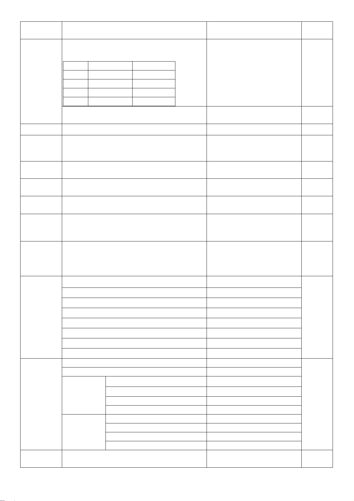
The variation of “KP320” is shown below.
This Service Manual is indicated for 7610.
Variation Note.
Product Code Trade Name
7610
XXXXXXXX KP320
KP320 SERVICE MANUAL V1.2
3
Page 5

This is the Electronic Service Manual for KP320 Triple Band GSM Digital
Cellular Telephone from LG. It contains specific information on repair and test
procedures.
For details of user functions, general operation and installation, please refer to the
User Guide.
The Service Manual is set out in the following sections.
1. Precautions for Repair Work : provides general guidelines for
undertaking safe and efficient repair work.
2. Unit Specification: provides the technical specifications for
KG195 Triple Band GSM Digital Cellular Telephone.
3. Introduction of Service Level :
a) Service Level 1:describes definition of Service Level 1, equipment and
tools required for this level.
b) Service Level 2 :describes definition, equipment and tools required for
Service Level 2.
4. Circuit Description: provides functional details of the circuits, block
diagrams and component purpose descriptions.
5. Servicing : defines the jigs, fixtures and test configurations required for
servicing the product; and describes the processes of assembly and
disassembly.
6. Troubleshooting : provides an aid to fault finding the product. Includes,
using the signal levels and plots at various parts of the circuit.
7. Device Information : provides functional information and pin-outs of
most of the semiconductor devices within the HHP.
8. Glossary :
terms used in this GSM and this manual.
KP320 SERVICE MANUAL V1.2
4
Page 6

Next Section >>
Main Menu
SECTION 2
2
Precautions
for Repair Work
KP320 SERVICE MANUAL V1.2
5
Page 7

PRECAUTION
Important
Please read the following cautions, notes and
warnings before progressing through this manual or
undertaking any repair action.
Remember: SAFETY FIRST!
CAUTION:
AC Power Cord:
Care must be taken not to damage the AC power cord as fire or electric shock may
result.
Battery Pack:
Only use the specified batteries and chargers with this equipment.
Do not short the battery terminals together.
Keep the battery pack away from fire and sources of ignition.
Remember to recharge the battery pack after each use.
Before Powering up the Equipment:
• Only switch on the telephone’s power once the test or installation set-up is
complete.
• Switching on at the wrong time may result in electric shock or damage to system
components.
• Always ensure that the power is switched off before making connections /
disconnection’s.
• It is important to check that the correct DC voltage is applied to the equipment to
prevent electrical damage.
Component Polarity:
Always check the polarity of connections and components before soldering.
Particular attention must be paid to IC.s, diodes, transistors, capacitors and any
other semiconductor device that is polarity dependent.
KP320 SERVICE MANUAL V1.2
6
Page 8

Electrostatic Damage (ESD):
Semiconductor devices are easily damaged by electrostatic discharge. Many of the
procedures detailed in this manual involve disassembly of the equipment and
therefore handling of the printed circuit boards.
To protect these devices from ESD a wrist strap connected to ground must be worn.
In addition to this the work surface must be covered with an anti-electrostatic mat,
which should also be grounded.
If printed circuit boards are to be stored without being re-assembled into their
equipment, then they must be kept in an anti-electrostatic bag.
Grounding:
Each piece of test equipment should be electrically grounded. A third (grounding)
pin is provided as a safety feature. Ensure that the electrical outlet also contains
this feature.
Cosmetic Protection during Repair Work:
Always ensure that the working surface is kept clean and free from abrasive
materials.
The LCD is very susceptible to scratches and damage. It should be covered with
clear adhesive vinyl while the equipment is disassembled.
Storage of Faulty Components:
Any components that are replaced due to failure should be kept safely in an antielectrostatic container. NEC’s Quality or Research & Development Departments
may require them to make quality and reliability investigations.
No Fault Found Equipment:
In some cases the reported symptom may not be apparent. You may subject the
equipment to a controlled amount of stress, vibration and temperature variation to
see if the fault occurs.
Care should be taken not to apply excessive stress or vibration or extreme
temperature variations as further faults may develop.
KP320 SERVICE MANUAL V1.2
7
Page 9

Soldering and Disordering :
The solder used is only Pb-free.
Fast, accurate and high quality soldering is required to minimize the risk of heat
damage to the electronic components.
It is necessary to adjust the temperature of soldering tip to 330 degrees or less.
The soldering tip should not be in contact with components or PCB tracks for longer
than 4 seconds (average). This time depends on temperature conditions of parts.
Heat the pad on the PCB and the lead, quickly apply solder, remove heat and cool.
After soldering is complete, ensure that all solder joints are of good quality - no dry
joints, solder bridges, cracks or excess solder.
The majority of chip components are machine mounted using solder paste.
Removal of the solder is not sufficient for chip component removal. Each solder
point must be heated simultaneously and quickly (to prevent component and PCB
damage). When the solder has melted, remove the component with tweezers.
Short Circuits:
Care must be taken to avoid short circuits. Soldering, solder dust, screws, metal
clippings, metal wrist watches etc. can cause short circuits on PCBs which may
result in component damage.
Test Equipment Calibration:
Your test equipment should be calibrated before use. Frequent calibration is
essential to ensure high quality and reliable repairs.
Cleaning:
Before cleaning ensure that the telephone is switched off and disconnected from the
power source. Cleaning should be done using a soft dry cloth. If the equipment is
heavily soiled a soft cloth soaked in a mild synthetic detergent diluted in water may
be used.
Never use benzene or any other chemicals to clean the equipment.
RF Shielding:
It is advisable to carry out detailed measurements and repair (in particular RX) in a
shielded area to minimize RF interference.
AC Adapter and Battery Charger:
The AC adapter and battery chargers are for indoor use only. Ensure that the
devices are not exposed to rain or moisture
KP320 SERVICE MANUAL V1.2
8
Page 10

Electrical Safety:
Electrical equipment is hazardous if misused. Any repairs must be carried out with
care and only by authorized personnel.
Ensure all power sources are switched off and power cords removed before
undertaking any repairs.
Hazardous Waste:
The battery pack, if incorrectly disposed of, is an environmental hazard. It must be
disposed of in accordance with the regulations of the country concerned.
Never dispose of the battery pack in fire or water.
Confidentiality:
The circuitry within this equipment contains several components that are regarded
as company confidential. Only use NEC specified parts as replacements.
RF Injury:
To avoid RF injury, direct exposure to radio frequency energy should be avoided. In
particular, exposed parts of your body (especially the eyes and face) should not
come into contact with the antenna while the equipment is transmitting.
Storage Conditions:
It is recommended that the following storage conditions should be avoided to
prevent damage to the equipment: Dusty.
Humid.
Near to magnetic equipment
In direct sunlight
Ventilation:
Repair areas should be well ventilated and fume extraction systems should be
installed where necessary. Potential hazardous substances are solder fumes, flux,
alcohol etc.
PCB Handling:
It is recommend that cotton gloves are worn during repair work. This is to protect
your hands from chemical contamination and to protect the PCBs from fingerprints
and humidity
.
KP320 SERVICE MANUAL V1.2
9
Page 11

SIM Card:
• Do not bend.
• Clean by using a soft dry cloth.
AUDIO Parts:
• Be careful for alien substance/oils and fats, etc. not to adhere to the terminal contact part of MIC, the
receiver, the speaker.
• Be careful to handle AUDIO parts with electrostatics measures at the worker/in the working place.
• Be careful not to spend a stress on the MIC side part to the utmost.
• Be careful not to pressurize the coil joint (protection Bond part) of the receiver and speaker because
they are easy of broken.
• Be careful for alien substance to approach to sound hole part of the speaker.
• Be careful sufficiently so as not to blow air with the process into the receiver, speaker/MIC sound hole.
It causes sounds being small by the diaphragm transformation or vibration.
10
KP320 SERVICE MANUAL V1.2
Page 12

<< Previous Section
Next Section >>
Main Menu
3
SECTION 3
Unit Specifications
11
KP320 SERVICE MANUAL V1.2
Page 13

3. UNIT SPECIFICATION
PRODUCT FEATURES AND SPECIFICATION
Solution MT6229
Type Bar type
Antenna Type Internal (tri-Band with Bluetooth)
Main Display 2.0” QVGA (240x320)
GPRS Class 10
MMS Yes, 1.1
Camera 3M
Battery 900mAh Li-ion inner pack
Audio player
FM Receiver
Yes (support MP3, WMA and AAC
playback)
Yes, US/Europe band
(87.5~108MHz)
MPEG4/H.263 Yes (support 3GP)
H.264 No (no support)
AAC+ Yes
FM as alarm Yes
Scheduled FM recording Yes
MP4 for incoming call/ power on
off animation and screen saver
Yes
Loud Speaker Yes
Media Tek
Audio player--real resuming Yes, for MP3 and WMA
Video recording Yes
Memory Size 1Gb NAND + 256Mb SDRAM
User memory 100MB
Internal NAND 1Gb
Memory Card Micro SD
Bluetooth Yes, version 1.2
USB Yes, slave 1.1
IrMC No
WAP Yes, 2.0
Java Yes
PoC No
EMAIL
No
Status LED Yes
DRM No
Dictionary No
MPEG4 caller ID
Finger handwriting
Yes
No
(TBC)
Up to 4GB
KP320 SERVICE MANUAL V1.2
12
Page 14
Touch Panel No
Caption
OTA
語言學習機(AB repeat)
Music Equalizer
Image Editing
In flight mode
No
Yes
No
Yes
No
Yes
ERAL REQUIREMENT
General Requirement
Category Requirement Description Parameter Support
Shall support multiple radio bands/power
- 850 MHz/class 4 (2W) N
Frequency
Antenna Shall support [Internal/External] antenna Internal Y
- 900 MHz/class 4 (2W) Y
- 1800 MHz/class 1 (1W) Y
- 1900 MHz/class 1 (1W) Y
GPRS
Data
Service
Java
Voice codec
Audio
decoder
Shall support GPRS bearer
- release [R#] R99 (Except EDGE) Y
- multi-slot class [class #] 10 Y
- Service class [Class #] Class B Y
- Coding scheme [CSn] CS1, CS2, CS3, CS4 Y
Shall support following data transaction mode
and services.
- Fax N
- Data N
- WAP [rel #] 2.0 Y
- SMS Y
- EMS [rel #] Code 5.0 Y
- MMS [rel #] 1.1 Y
Support JAVA MIDP [ver #] 2.0 Y
Support JAVA CLDC [ver #] 1.1 Y
Shall support multiple voice codec Y
- FR Y
- EFR Y
- HR Y
- AMR NB (air link (Channel Coding)) Y
- AMR WB (Sound Recording) Y
Shall support multiple audio decoders
- MP3 Y
- WMA Y
- AAC Y
- AAC+ Y
KP320 SERVICE MANUAL V1.2
13
Page 15
Category Requirement Description Parameter Support
Physical
Display
Camera
FM radio
Battery
The physical dimension is [Length x Width x
Thickness mm]
The overall volume is [# cc] 69.5 cc Y
The weight is [# g] 81.5 g Y
Shall support main display with following
characteristics:
- Size 2.0” Y
- Type TFT, Transmissive Y
- Color depth 262K Y
- Pixel resolution [width x height] 240x320 Y
- Active area [W x H mm]
Shall support high resolution camera with
following characteristics:
- Active pixel array up to resolution [ X x Y
pixels]
- Sensor type [CMOS or CCD] CMOS Y
Shall support FM radio bands
- US/Europe band 87.5~108MHz Y
- Japan band 76~90MHz N
Shall support Li-Ion battery with minimum
capacity of [mAh].
Shall support following device to connect
external devices.
107.3x46.6x13.9 (mm) Y
Y
30.6mm(W) x 40.8mm
(H)
Y
2048 x 1536 Y
900mAh Y
Y
Connectivity
Storage
Indication
- USB [ver, host or slave or OTG] 1.1 slave Y
- Bluetooth [ver, power class] 1.2, class 2 Y
GAP
SDAP
DUN
SPP
- Bluetooth profiles
Shall support mass data storage for different
multimedia content.
- Build-in NAND [MB]. Used as mobile disk.
(Notes: Designed footprint shall be possible to
support multiple memory capacity)
- Micro SD Y
Shall support LED for status indication. N
Shall support LED for charger (TA or USB) plugin status indication.
HSP
HFP
OPP
FTP
A2DP, AVRCP
Y
Y
By display
Y
N
KP320 SERVICE MANUAL V1.2
14
Page 16

Category Requirement Description Parameter Support
Vibrator Shall support in built vibration alert Y
SIM Card Shall support SIM card both 1.8V and 3V. Y
Shall support
- 12 alphanumeric/number keys (0-9,#,*)
- 4 function keys (on hook, off hook, left
Keypad
softkey, right softkey)
- 5 way navigation keys (up, down, ok, left,
right)
- 3 side keys (side up, side down and camera
key)
Shall support illumination color [color] for
keypad backlight.
Shall design in a nub on or around key number
5.
Shall support AWB (Automatic White Balance) Y
Y
2 LED (Blue) with light
guide
film
Y
Y
Camera
TV-OUT Shall support TV-OUT function Y
Shall support automatic flicker reduction N
Shall support gamma correction Y
15
KP320 SERVICE MANUAL V1.2
Page 17

Performance Requirement
g
Category Requirement Description Parameter Support
Standby
Time
Talk Time
MP3 play
time
Video play
time
Bluetooth
Standby
Time
FM Radio
Current
consumption
RTC
RF
Antenna
Shall support minimum test hours as [hrs]
based on battery capacity of [mAh]
(Reference measurement conditions refer to
TW-09)
Shall support minimum test minutes as [min]
based on battery capacity of [mAh]
(Reference measurement conditions refer to
TW-09)
Shall support MP3 play at least for [# hrs]
assume stereo headset is attached
Shall support Video play at least for [# hrs]
assume stereo headset is attached
Shall support minimum test hours as [hrs]
based on battery capacity of [mAh]
Shall support minimum current [mA]
The real time clock shall be able to sustain
for at least [#hrs] after removing the
battery.
The RF performance shall comply with 3GPP
TS45.005. The internal/special RF
performance requirement are defined as
below.
Shall exceed the sensitivity performance
[dBm] in GSM band under conditions of
static channel, extreme conditions without
fading.
Shall exceed the sensitivity performance
[dBm] in DCS band under conditions of static
channel, extreme conditions without fading.
Shall exceed the sensitivity performance
[dBm] in PCS band under conditions of static
channel, extreme conditions without fading.
Antenna performance test shall be done
according to [#] standard
The GSM TRP (Total Radiated Power), when
transmitting at the maximum power, shall be
no less than [dBm] (low, middle, high
channel)
The DCS TRP (Total Radiated Power), when
transmittin
no less than [dBm] (low, middle, high
channel)
at the maximum power, shall be
↑ 240 hrs & ↓ 3.4mA @
900mAh (P.P.: 5)
Standby time = Capacity/
Standby current
Ç3 hrs@900mAh (PCL: 5)
Talk time = 95% Capacity /
Talk current)
15 hrs @900mAh Y
4hrs Y
150hrs@ Paging period: 5 Y
È40mA @Paging period: 2
10hrs (25 degree C) Y
-105dBm
-105dBm
-105dBm
CTIA Y
Free space: Ç28dBm
Body: Ç21dBm
Free space: Ç25dBm
Body: Ç19dBm
Y
Y
Y
Y
Y
Y
Y
Y
Y
16
KP320 SERVICE MANUAL V1.2
Page 18
Category Requirement Description Parameter Support
Free space: Ç25dBm
Camera
Video
Display
The PCS TRP (Total Radiated Power), when
transmitting at the maximum power, shall be
no less than [dBm] (low, middle, high
channel)
The flatness of TRP of the same band shall
be within
The TIS of GSM band shall be better [dBm]
The TIS of DCS band shall be better [dBm]
The TIS of PCS shall be better [dBm]
The flatness of TIS of the same band shall
be within
The SAR value shall NOT exceed [W/kg] with
10g averaging
Camera module shall support following toplevel specification.
- Sensitivity 490mV/Lux·sec Y
- Dynamic Range 60.0dB Y
- FOV 60.8o (diagonal) Y
- Focus
Shall support preview up to [resolution
@fps] on main display.
Note: The actual visual quality might be up
to the response time of LCD.
The time spacing between two consecutive
burst capture shall be less than [# sec]
Shall support recording with the maximum
frame rate (fps) in specific video resolution,
[resolution @ # fps]
Shall support playback with the maximum
frame rate (fps) in specific video resolution
Main display shall sustain the following
specification.
- Typical central Luminance [# cd/m2] 200 cd/m2 @handset level Y
- No conspicuous cross talk observed on test
pattern.
(24dBm: in case of minor
band)
Body: Ç19dBm
(18dBm: in case of minor
band)
2dB.(low, middle, high
channel)
Free Space: È-103dBm
Body: È-97dBm
Free Space: È -103dBm
Body: È-97dBm
Free Space: È-103dBm
(-102dBm: in case of minor
band)
Body: È-97dBm
(-96dBm: in case of minor
band)
2dB.(low, middle, high
channel)
1.3 Y
Y
10cm -∞ Auto Focus
240X320@ 30fps
2 sec @ 320x240 image size
stored to Micro SD card
CIF @ 15fps Y
CIF @ 30fps Y
Y
Y
Y
Y
Y
Y
Y
Y
Y
Y
Y
KP320 SERVICE MANUAL V1.2
17
Page 19
Category Requirement Description Parameter Support
- The chromaticity of main display should be
better than
Toleran
x y
R 0.633 0.350
G 0.326 0.599
ce:+-
0.05
Component spec Y
B 0.147 0.069
W 0.306 0.319
- The contrast ratio of main display should
be better than [#] at normal temperature
Acoustic
300 @ Handset level Y
Ringer
Volume
Charge
Current
Antenna
Display
Uplink audio shall be Compliant with 3GPP
TS43.050 V4.00 (Referring to TS26.131 &
Y
132)
Downlink audio shall be Compliant with 3GPP
TS43.050 V4.00 (Referring to 26.131 & 132)
The TDD noise in downlink direction shall be
better than [# dB] (Max power)
The TDD noise in uplink direction shall be
better than [# dB] (Max power)
At least 58 dBspl under below conditions:
1. Ringer set as ringer.
2. Test distance set as 1 m
Fast Charge (TA):
Fast Charge (USB):
Pre-Charge:
Total Charging Time:
-62dBm
-62dBm
Under 58dB : 0 %
≥ 58 dB : 100% ↑
≥ 63dB : 60% ↑
650 ±65 mA
450 ±45 mA
50 ±15 mA
≤ 3 hours
Y
Y
Y
Y
Y
Antenna Bar indicator Rx power
7 -91dBm ~
5 -95dBm ~ -91dBm
4 -99dBm ~ -95dBm
Y
2 -103dBm ~ -99dBm
1 -105dBm ~ -103dBm
0 ~ -105dBm
Battery
Indicator
Low voltage
Warning
Off No Service
Battery Indicator Voltage
Y
Full Charge 4.20 ± 0.05V
Discharge
3 Î 2
2 Î 1
1 Î 0 (Blinking)
0 Î 0ff
3.72 ± 0.05V
3.62 ± 0.05 V
3.54 ± 0.05 V
3.35 ± 0.05 V
0 (1st Bar Blinking) Under 3.62 ± 0.05 V
Charge
0 Î 1 (2nd Bar Blinking)
1 Î 2 (3rd Bar Blinking)
2 Î 3 (4th Bar Blinking)
Warning tone duration
3.62 ± 0.05 V
3.72 ± 0.05 V
4.20 ± 0.05 V
Warning tone once per two
minutes
Y
18
KP320 SERVICE MANUAL V1.2
Page 20

Category Requirement Description Parameter Support
3.54V± 0.05V during call
3.50V± 0.05V during stand
by
RD: 600kB/s
WR: 200kB/s
Y
Y
Forced shut
down
voltage
USB
Voltage
3.35V ± 0.03V
The average USB connection throughput
between ME and USB should be better than
[# kB/s]
19
KP320 SERVICE MANUAL V1.2
Page 21
Software Function
4-1 System Specification
Item Target Specification
Form Factor Bar Type
Size 107.3x46.6x13.9 (mm)
Weight 81.5 g
Battery 3.7V, 900mAh Li-Ion
Talk Time 3 hrs @900mAh @GSM900 PCL 5
Standby Time 240 hrs @900mAh @ Paging period 5
Antenna Embedded type
LCD 262Kcolor, 240x320 TFT
FM Radio Yes, FM band only
Camera 3M Pixel Auto Focus
Back Light White LED
Keypad Backlight Color Blue LED
Vibrator Yes
Loud Speaker Yes
Microphone Yes
Earphone Jack Yes (MMI)
SIM Socket Yes, 1.8/3.0V
Volume Key Side key
Basic Accessory
Travel Adaptor
Standard Battery (900mAh, Li-Ion)
Stereo Headset with button
USB Data Cable
TV Out cable (Option)
4-2 General Features
Function Target Specification
Basic Display
Speech Codec FR/EFR/HR/AMR
Keypad
User Profile
(Audio Settings)
RSSI (7 Levels <<Off, 0~2, 4~5, 7>>)
Battery Indicator (4 Levels, 0~3 for charging; 5 Levels, 0~4 for
discharging)
Icons Indicator
Others reference to "Phone Personalization Setting"
Number of Keys: 24 Key (include 12 alphanumeric/number keys (0-9,#,*),
4 function keys, 5 way navigation keys, 3 side keys)
Soft Function Keys: 2
International Access (+)(long 0)
User Selectable and Customizable Profiles (7 profiles: General, Meeting,
Outdoor, Vibrate only, Headset, Silent, Bluetooth)
Auto-detect and activated profiles (1 profile: Headset)
Key Tone
Key Tone Volume (7 Level - 0 ~ 6, 0 for Mute)
KP320 SERVICE MANUAL V1.2 20
Page 22

Key tone setting (4 sets: Silent, Click, Keyboard Tone, Melody Tone,
English/Russia Human voice)
Ring Tone
Ring Tone Volume (7 Level - 0 ~ 6, 0 for Mute)
Built-in Ring Tone Pattern: 20
Customizable Ring Tone Link: 5
Intelligent Call Alert
Digits To Sound Synthesizing
Alert Type
5 Types - Ring, Vibration Only, Vibration and Ring, Ring after vibration,
Light Only, Beep Once
Power On Tone
Built-in Ring Tone Pattern: 5 (include Silent)
Power Off Tone
Built-in Ring Tone Pattern: 5 (include Silent)
Message Tone
Built-in Ring Tone Pattern: 8 (include Silent)
Warning Tone
Built-in Ring Tone Pattern: 1 (Only On/Off operation)
Error Tone
Built-in Ring Tone Pattern: 1 (Only On/Off operation)
Camp On Tone
Built-in Ring Tone Pattern: 1 (Only On/Off operation)
Connect Tone
Built-in Ring Tone Pattern: 1 (Only On/Off operation)
Answer Mode
Management
Tools and Utilities
Any Key Answer
Auto (Only available for headset mode while headset plugged in)
Calendar - Month view only Personal Information
To do list - 6 fields (Date, Start time, End time, Note, Alarm, Repeat)
Alarm
5 sets of Alarm
4 major fields for each set - On/Off, Time, Repeat type, Audio options
World Clock
Cities list: China(52),IND(54),CIS(68) cities
Daylight saving time support: activated by user selection
Home city set
Calculator
Addition, Subtraction, Multiplication, Division
Unit Converter
Weight, Length
Currency Converter
Health
BMI, Menstrual
Phone Personalization Greeting Text
KP320 SERVICE MANUAL V1.2 21
Page 23

Setting
Security Phone Lock, SIM Lock, Auto Keypad Lock, Fixed Dial, Barred Dial
Input Method
Home Shortcut
Call Information Display
Flight Mode
Time and Date Setting
Wallpaper
Screen Saver
Power On Animation
Power Off Animation
LCD Backlight
PLMN/Service Indicator (Display of PLMN Name/Service Provider Name
from SIM)
Date Time Display
Own Number Display
Restore Factory Default Setting
Main Menu Style Setting
Themes Setting
Engine
T9
Support Language
Depends on customer and market requirement.
Total supported languages will be limited to memory condition.
Game
File Management
Predictive word input
2 embedded games: Cricket and Sudoku
2 embedded Java Games: Mini Game World, Chequered Flag
Settings:
BGM, Sound Effect, Vibration
Hidden root directories except five folders as fellows:
Audio, Images, Other, Received, Video
Limit the actions on root directories.
No create/rename/delete options on root directories.
Total Memory: 90MB
KP320 SERVICE MANUAL V1.2 22
Page 24

4-3 GSM/GPRS Features
Function Target Specification
GPRS GPRS Multi slot Class 10
Data Service BS 24 - 26 (2400-9600 bit/s), asynchronous, non-transparent, UDI.
CSD rate up to 9.6K bit/s
Call History
Call Cost
GPRS Counter
Call Management
Call
Related Supplementary
Services
Last Dialed Number: 40
Last Received Number: 40
Last Missed Number: 40
Scratch Pad Memory (Save an input number in call): 1
Last Call Time
Total Dialed Call Time
Total Received Call Time
Last Call Cost
Total Cost
Reset Cost
Max Cost
Price Per Unit
Last Sent (unit in Byte)
Last Received (unit in Byte)
All Sent (unit in Byte)
All Received (unit in Byte)
Call Swap
Call Retrieve
Automatic Redial
Speed Dialing
Last Number Redial
Call Hold
Call Waiting
Calling Line Identity Presentation
Calling Line Identity Restriction
Connected Identification Restriction
Call Divert All voice Calls
Call Divert if unreachable
Call Divert if no answer
Call Divert if busy
Call Divert all data calls
Cancel all divert
Call Barring All Outgoing Calls
Call Barring All Outgoing International Calls
Call Barring All outgoing International except home
Call Barring All incoming Calls
Call Barring All incoming Calls when roaming
Multi-party Call (up to 7 calls, 5 in conference, 1 on held, 1 waiting)
KP320 SERVICE MANUAL V1.2 23
Page 25

Phone Book
Line switching (Line1, Line2)
Call reminder (Off, Single, Periodic)
Closed User Group
Quick Search (Notice: Quick search function only works in Phonebook,
SMS and MMS. In other application, this phone supports regular search.)
Alphabetical Store and Recall
Access Phone Book in call
Copy & Move
Fixed Dial Number
Service Dial Number
Speed Dial Number
SOS Number
Entry: 1000 names (12 fields – Name, Mobile, Home, Company name,
Email address, Office number, Fax number, Birthday, Associate Picture,
Associate Video, Associate Sound, Caller group)
Caller Group-5 caller group- Friends, Family, VIP, Business, Others (5
fields – Name, Ring, Picture, LED pattern, Video, Member list)
Own Numbers: User can change the own numbers of handset. (Sets of
own numbers depends on SIM)
Message
vCard: (Edit, Send and Receive. 7 fields – Name, Mobile, Home, Company
Name, Email Address, Office Number, Fax Number)
Note: This phone doesn’t support phone number search.
SMS
Standard SMS
SMS Reply Path
SMS Delivery Report
Valid period (1 hour/12 hours/1 day/1 week/Maximum)
Message Type (Text, Fax, Page, Email) Message Indication Type refer to
GSM 03.40
Basic text-only SMS as described in 3GPP TS 23.040 R5
Notice: This phone doesn’t support video ring tone via SMS
SMS Character Sets Support
GSM7
UCS-2
EMS
EMS Standard as described in 3GPP TS 23.040 R5 excluding WVG
EMS Text Format
Text Style: Normal, Bold, Italic, Underlined, Strikethrough
Text Alignment: Left, Right, Center
Text Size: Normal, Large, Small
EMS Image Support
1-bit small image 16x16 pixels black and white
1-bit large image 32x32 pixels black and white
1-bit variable image in single SMS packet
Extended black and white 1-bit image up to 255x255 pixels
Extended 6-bit image up to 255x255
KP320 SERVICE MANUAL V1.2 24
Page 26

Pre-defined animation
User-defined small animation 8x8 pixel 4-frame black and white
User-defined large animation 16x16 pixel 4-frame black and white
Pre-defined sound
User-defined i-Melody up to 128 bytes
LZSS compression algorithm
Re-use extended object
Object Distribution
User Prompt Indicator
Hyperlink format element
Extended Object Distribution
Notice: This mobile doesn’t support Nokia smart message format
(including WBMP), only support *.ems format" Æ subject to Nokia smart
message license
EMS Character Sets Support
GSM7
UCS-2
EMS Miscellaneous
SMS Concatenation ( 8 Segments for MT/MO)
SMS Compression
MMS
MMS Standard as described in 3GPP TS 23.140 V4.8.0
Extract media from Message
Insert Media into message
OTA provisioning partially support (Network Profile setting
Auto download mode
Manual download mode
Operator can pre-configure the delivery mode
MMS notification with icon or Pop-up message display)
MMS Message Format
MMS SMIL (A subset of SMIL descried in the MMS Conformance
Document 1.2)
MMS Character Sets Support
US-ASCII
Unicode
ISO-8859-1
UTF-16
UTF-8
MMS Images Support
WBMP Wireless bitmap
GIF87
GIF89a
JPEG
MMS Sound Formats Support
WAV
AMR
KP320 SERVICE MANUAL V1.2 25
Page 27

MIDI
MP3
i-Melody
MMS Miscellaneous
Multipart binary MIME
Storage
Separated Inbox folder for SMS and MMS
Separated Outbox folder for SMS and MMS
Total 300 SMS in the storage of phone plus SIM including Inbox and
Outbox (Phone could supports 260sets SMS including Inbox and Outbox.
The maximum SMS s8tored in SIM are 40sets. It means the actual SMS
quantities in Inbox and Outbox are among 260 to 300. )
Total 100 MMS in the phone storage including Inbox, draft and Outbox
Notice: Total MMS count need depends on user memory space.
Common Operation
Write Message
Read Message
Edit Message
(For MMS, Edit only conformance messages, unknown media not
supported, unknown SMIL not supported)
Cell Broadcast
Network
SIM
Reply Message
Send Message
Delete Message
Forward Message
Use Sender's Number
Message Templates
Extract media from Message (MMS/EMS)
Store Media (MMS/EMS)
Delete Media (MMS/EMS)
Read Cell Broadcast
Cell Broadcast Mode: Receive On/Off
Cell Broadcast Message Language
Channel Setting
Automatic Network Selection
Manual Network Selection
Network Service Status
Preferred Network (User definition)
GPRS connection mode selection: Always, When Needed
Common Operation
SIM Application Toolkit (Release 98 Class 2 certified)
Security
PIN
Personalization (Service provider lock, Network lock)
DTMF Signaling
DTMF Enable & Disable DTMF
KP320 SERVICE MANUAL V1.2 26
Page 28
4-4 Multimedia Features
Function Target Specification
Camera
Image size:
240X320, 320X240, 640X480, 1280X960, 1600X1200, 2048X1536
Continuous Shot: 9 shot, 5 shot, 3 shot, OFF
Zoom: 1x ~ 4x
Image Quality: High, Normal, Low
White Balance:
Auto, Daylight, Tungsten, Fluorescent, Cloud, Incandescence
Shot: Three Shot Sounds
EV: -4 ~+4
Scene Mode: Auto, Night
Banding: 60Hz/50Hz
Effect settings: (Total 14 types)
Normal, Grayscale, Sepia, Sepia Green, Sepia Blue,
Color Invert, Gray Invert, Blackboard, Whiteboard,
Copper Carving, Blue Carving, Embossment, Contrast, Sketch
Image Viewer
No. of the Stick Frames: 3
Frame 1, Frame 2, None
Stick Frame Only can be used while image size is 240WX320H
Storage Selection: Phone, Memory card
(Only available when external memory card supported)
Delay timer: Off/ 5/ 10/ 15 Sec
Light: Off/Auto/Always on/When taking
Thumbnail supported
Browse Style: List, Matrix
View
Forward:
To Wallpaper, Phonebook, Screen Saver, Power On Display, Power Off
Display, MMS, Bluetooth
Rename
Delete
Delete All
Sort: By Name, Type, Time, Size, None
Storage Selection: Get list from Phone, Memory card
(Only available when external memory card supported)
Image Format Support
JPEG Baseline
GIF87a
GIF89a
WBMP
BMP
Music Player Play
KP320 SERVICE MANUAL V1.2 27
Page 29
Pause
Resume
Stop
Next
Previous
Storage Selection: Get list from Phone, Memory card
(Only available when external memory card supported)
Auto-Generate Playlist
Skin: 2 skins
Spectrum display style: 2 styles
Repeat Mode: Off, One Song, All Songs
Shuffle Play
Background Play
Equalizer Setting: 8 sets
Normal, Bass, Dance, Classical, Treble, Party, Pop, Rock
Volume Control: 7 levels (0 ~ 6, 0 for Mute)
Playlist Edit: Add, Remosztve, Remove All
Sound Format Support
Video Player
Video Recorder
MP3
AMR
MIDI
WAV
AAC
Play
Pause
Stop
Speed Control: X1, X2, X4, X8, X1/2
Forward:
To Phonebook, Screen Saver, Power On Animation, Power Off
Animation, MMS, Bluetooth
Rename
Delete
Delete All
Sort: By Name, Type, Time, Size, None
Storage Selection: Get list from Phone, Memory card
Volume Control: 7 levels (0 ~ 6, 0 for Mute)
White Balance:
Auto, Daylight, Tungsten, Fluorescent, Cloud, Incandescence
EV: -4 ~+4
Night Mode: On/Off
Banding: 60Hz/50Hz
Video Quality: Fine, High, Normal, Low
File Size Limit: No Limit, 95KB, 195KB, 295KB,
Record Time Limit: No Limit, 15 sec, 30 sec, 60 sec
Record Audio: On/Off
KP320 SERVICE MANUAL V1.2 28
Page 30
Encode Format: MPEG4, H.263
Effect settings: (Total 14 types)
Normal, Grayscale, Sepia, Sepia Green, Sepia Blue,
Color Invert, Gray Invert, Blackboard, Whiteboard,
Copper Carving, Blue Carving, Embossment, Contrast, Sketch
Storage Selection: Phone, Memory card
(Only available when external memory card supported)
Record
Pause
Resume Recording
Stop
Sound Recorder
Melody Compose
FM Radio
Storage Selection: Phone, Memory card
(Only available when external memory card supported)
Encode Format: WAV, AMR,AWB
Audio Quality: Low, High
Record
Pause
Resume Recording
Stop
Edit
Play
Save
Instrument Selection: 10 types
Piano, Guitar, Violin, Saxophone, Steel Drums, Flute, Harmonica,
Trumpet, Music Box, Xylophone
Play Speed: Fast, Normal, Slow
[Notice] Melody composer only support one instrument in one imelody
file, so the last chosen instrument will be used to play this imelody file
Frequencies: 87.5 ~ 108.0
Skin: 2 skins
User definable Preset Channel List
Channel Auto Search
Background Play
Record
Record Format: AMR, WAV, AWB
Record Storage: Phone, Memory Card
(Only available when external memory card supported)
Preset Channel List generated by auto search
JAVA
MIDP 2.0
CLDC 1.1
Memory Limit – Heap size 1.5MB
Support JSR 139,118,120,135,185, 75
KP320 SERVICE MANUAL V1.2 29
Page 31

4-5 Connectivity Features
Function Target Specification
WAP
WAP 2.0 Spec.
WAP Push OTA/Message
WAP Provisioning Service
CSD/GPRS data connection
Bookmark
Wireless Telephony Application (WTA) support:
Only Public WTA support, supported functions listing below * Make a telephone call
* Send a string of DTMF tones over an established voice connection
* Add an entry to the telephone book of the device
Support OTA push and push message
OTA Provisioning & OTA download
Supports WML, WCSS, XHTML mp
Version 1.2 Bluetooth
Profile: GAP; SDAP; DUN; SPP; OPP; HSP; HFP; FTP; A2DP; AVRCP
USB
Mass Storage Device
Virtual COM
TV-OUT
4-6 GSM/GPRS Features
Browser
WAP WAP2
wap version 2.0 / WML version : 1. 3 WAP2
WAP 2.0+MMS+Push / Yes
-WML version : 1.3 xhtml version : 1.0 WML 1.3 / XHTML 1.1
Character sets supported in WAP browser (UTF-
8 (Default), UTF-16, USASCII, Latin1, UCS2,
ISO-8859-1, UTF-8, UTF-16, ISO-10646-UCS-2,
USASCII)
Contents Decoder Base64, Quote-Printable
WBMP Wireless bitmap, GIF87, GIF89a, PNG,
JPEG, JPG, BMP, AMR, MIDI, MID, IMELODY,
MP3, 3GP, AAC
Status Function Target Specification
Code base
07A (KP320)
utf-8, iso-8859-1, us-ascii,
iso-10646-ucs-2
JPG,JPEG,GIF,WBMP,BMP,PNG
MP3,MIDI,MID,AMR,MMF,WAV,MPEG,MP
G,AAC
3GP,MPEG4,MP4,3GPP
KP320 SERVICE MANUAL V1.2 30
Page 32

4-7 WAP
Value Comments Function Description
General
Bearer
Language
Browing
Type of Browser (Browser Name)
Version of the Browser
The usable size of the device's screen in units
of pixels (px*px)
Size of the device's screen in units of
characters. (Number of characters per
row)x(Number of rows). In calculating this
attribute use the largest character in the
device's default font.
Size of the device's screen in units of
characters. (Number of characters per
row)x(Number of rows). In calculating this
attribute use the smallest character in the
device's default font.
Browser version interrogation capability via
keypad
Factory configuration option available
Bearer Selection available to end user via
multiple profiles or via bearer options in each
profile (circuit or Packet if both available):
Bearer Dependent Display Indication
supported (ie End user must be able to
differentiate between WAP over a circuit
connection from WAP over a Packet
connection due to likely charging
implications)
GPRS
CSD
Automatic bearer selection
Version of WML supported by the browser
WML script support
Version of XHTML supported by the browser
Version of HTML supported by the browser
Maximum WML Deck Size supported (WML
Binaire)
Is the attribute hspace for images ignored by
the device?
Is it possible to select/download images with
the device?
KP320 SERVICE MANUAL V1.2 31
Code base
07A
Obigo
Q03C
240X320
Variable font
width.
Variable font
width.
No
No
Yes multiple profile
Yes For CSD,
Yes
Yes
No
1.3
Yes
1.1
1.1
30KB But it depends
No
Yes
selection with
bearer in CSD or
GPRS
there's a
dialing up
progress screen.
End-user could
sense currently
using CSD.
on assigned total
memory pool.
And by content
diversity, the
value is dynamic.
TAG/
Page 33

Value Comments Function Description
WTA
Tables supported? Yes/No
Is it possible to mask table's border? Yes/No
Is there automatically a break line after a
link? Yes/No
Labels for links supported in the Soft key?
Yes/No
Possibility to use Select List for links? Yes/No
Card title supported? Yes/No
Is the Back function existing by default for the
handset? Yes/No
Tag <noop/> supported? Yes/No
Multiple choice and single choice for
checkbox supported?
Input fields supported?
Styles of characters supported?
(<u><i><em>…)
Image and text on the same line supported?
Image and link on the same line supported?
Link inside a text paragraph supported?
Horizontal alignement supported? Yes/No
WAP CSS supported (WAP2.0)? Yes/No
WTAI supported?
Code base
Yes
No
No
No
No
Yes
Yes
Yes
Yes
Yes
Yes
Yes
Yes
Yes
Yes
Yes
Yes
07A
Security
WTAI make call function supported?
WTA Save in phonebook
WTA Send DTMF
WTAI location function supported?
WTLS supported?
TLS supported?
WAP forum certification
Clear Display Indication that WTLS Security is
successful for a given session
Clear Indication that user has
accessed/exited a secure site
1. WTLS Class 2 with >= 128 bit encryption
2. WTLS Class 3 with >= 128 bit encryption
Supported Algorythms
Support of WIM
Certificates store supported?
1. Verisign
2. Baltimore
3. Certicom
4. Diversinet
5. Entrust
Yes
Yes
No Currently
No
Yes
Yes
Yes
Yes
No
Yes
Yes
SHA-1, MD5
No
Yes
Yes
No
No
No
Yes
there's no this
scenario on
handset.
KP320 SERVICE MANUAL V1.2 32
Page 34

Value Comments Function Description
Profile/
Bookmark
OTA/
Push
Stack
6. Globalsign
Multiple WAP Profile Capability
WAP Profiles Editable by - End User
WAP Profiles Editable by - OTAC (via SMS)
Maximum Number of WAP Settings
Maximum number of bookmarks in the
handset
Maximum number of characters for an URL
managed by the handset for GET and POST
method
Support OTA Provisionning for the WAP
Client? If yes, Which type of OTA?
1. View settings
2. Accept preconfiguration settings
3. Reject preconfiguration settings
WAP Push Alerts
Push bearer SMS
Push bearer WAP
Push SI (Service Indication)
Push SL (Service Loading)
Push CO (Cache Operation)
Push SIA (Session Initiation Application)
Maximum number WAP Push that can be
stored/ Memory dimension reserved to WAP
Push
is it possible to read Wap push later on ?
SyncML parameters OTA provisioning (Y/N)?
E-mail parameters OTA provisioning
IM client parameters OTA provisioning
MMS parameters OTA provisioning (OMA,
proprietary, none)?
* if OMA : SIM card provisioning support
(Y/N)?
* If YES : could you describe the way to
manage the parameters in
the SIM and the parameters in the phone?
WAP parameters OTA provisioning support
(OMA, proprietary, none)?
* if OMA : SIM card provisioning support
(Y/N)?
* If YES : could you describe the way to
manage the parameters in
the SIM and the parameters in the phone?
SAR supported? Yes/No
Is WTP Concatenation supported by the
mobile? Yes/No
Code base
07A
No
Yes
Yes
Yes
10
20 Customizable
1024
Yes, OMA OTA &
Nokia&Ericsson
OTA
Yes after set up.
Yes
Yes
Yes
Yes
Yes
Yes
Yes
Yes
Yes
15
Yes
Yes
Yes
Yes
OMA, SIM card
Provisioning
support (N)
OMA, SIM card
Provisioning
support (N)
Yes
Yes
KP320 SERVICE MANUAL V1.2 33
Page 35

Value Comments Function Description
Cache/
Cookie
Download
Can the Connect and the Get be sent in the
same PDU? Yes/No
Is the mobile able to send multiple GET in the
same PDU in case of complex pages (at least
2 images)?
Is the mobile able to send multiple GET in
rafale without waiting for to acknowledge the
reply in case of complex pages (at least 2
images)?
WP-HTTP
WP-TCP
WP-TLS
Dual Stack 1.x/2.0
Cache size (bytes)
Default behaviour in case no caching control
has been defined for a WML or XHTML page?
Default behaviour in case no caching control
has been defined for an image?
Where is the cache stored (RAM, flash
memory, ...)?
Cache control using HTTP headers
supported?
Attributes for Cache control supported in
HTTP headers (expires, max-age, no-cache, …)
Cache control using HTTP-EQUIV meta tags in
the WML or XHTML content supported?
Attributes for Cache control supported for
HTTP-EQUIV meta tags (expires, max-age, nocache, …)
Cache Operation Support as defined by WAP
Forum in WAP1.2.1 spec or WAP2.0 spec
Are cookies supported by the handset?
Yes/No
Lifetime
Empty cache function (Y/N)
Maximum SDU Size as Server (bytes)
Maximum SDU Size as Client (bytes)
Maximum number of images per page
Maximum size for an image (bytes)
Prefered image format
Type of Multipart supported in MIME Type
format
Code base
07A
No
No
No
Yes
Yes
Yes
Yes
50KB Customizable
Reload Always
Reload
Flash memory
(system drive)
Yes
Expire, max-age,
Etag, LastMofified-Since,
no-cache.
Yes
Expire, max-age,
Etag, LastMofified-Since,
no-cache.
Yes
Y
Y
Y
104856700 WSP
104856700 WSP
Common memory
pool
Common memory
pool
Gif, JPG, WBMP
All object formats
that could be used
on handset
KP320 SERVICE MANUAL V1.2 34
Page 36

Value Comments Function Description
Code base
07A
Audio Files
JAR download over WSP/HTTP
Support of TCP network connection
All object formats
that could be used
on handset
Yes
Yes
* Battery life is Network dependent; variations may occur.
The KG195 HHP works closely with the network and the standby and talk times achieved depend
upon this. In particular the location of the HHP within the network, the type of SIM, reception of
area messages, the use of AMR, Full Rate speech, Half Rate speech or Enhanced Full Rate
speech and other factors will affect both standby and talk times.
Transmitting Frequency
Range:
Receiving Frequency
Range:
TX - RX Duplex Spacing: EGSM : 45MHz
Channel Spacing: EGSM : 200KHz
Number of Channels
(ARFCN):
Power Class:
Tx Peak Current:
GPRS Class:
GPRS Coding Scheme:
Data Rates (Packet):
Data Rates (Circuit
Switch):
EGSM : 880 - 915MHz
DCS1800 : 1710 - 1785MHz
PCS1900 : 1850 - 1910MHz
EGSM : 925 - 960MHz
DCS1800 : 1805 - 1880MHz
PCS1900 : 1930 - 1990MHz
DCS1800 : 95MHz
PCS1900 : 80MHz
DCS1800 : 200KHz
PCS1900 : 200KHz
GSM : 124 (Numbered 1 to 124) std.
EGSM : 50 (Numbered 975 to 1023 & 0)
DCS1800 : 374 (Numbered 512 to 885)
PCS1900 : 299 (Numbered 512 to 810)
EGSM : Class 4 MTS (33 +/- 2dBm)
DCS1800 : Class 1 MTS (30 +/- 2dBm)
PCS1900 : Class 1 MTS (30 +/- 2dBm)
2500mA
Class 10; Operation class B
CS1/CS2/CS3/CS4
EGSM/DCS1800/PCS1900 :
Uplink : Up to 21.4Kbps (1 slot)
Downlink : Up to 85.6Kbps (4 slots)
EGSM/DCS1800/PCS1900 : Up to 9600Kbps
KP320 SERVICE MANUAL V1.2 35
Page 37

TRANSMITTER (EGSM)
RF Power Output
Power Levels 15 decrements in 2dB steps
Power Control Level 5 33dBm +/-2dB
Power Control Level 6 31dBm +/-3dB
Power Control Level 7 29dBm +/-3dB
Power Control Level 8 27dBm +/-3dB
Power Control Level 9 25dBm +/-3dB
Power Control Level 10 23dBm +/-3dB
Power Control Level 11 21dBm +/-3dB
Power Control Level 12 19dBm +/-3dB
Power Control Level 13 17dBm +/-3dB
Power Control Level 14 15dBm +/-3dB
Power Control Level 15 13dBm +/-3dB
Power Control Level 16 11dBm +/-5dB
Power Control Level 17 9dBm +/-5dB
Power Control Level 18 7dBm +/-5dB
Power Control Level 19 5dBm +/-5dB
TX Frequency Output
Low Channel (Ch 975) 880.2 MHz
Mid Channel (Ch 62) 902.4 MHz
High Channel (Ch 124) 914.8 MHz
TX Frequency Calculation (Ftx)MHz
(0 - 124)
(975 - 1023)
890 + (ARFCN x 0.2)MHz
890 + 0.2x(ARFCN - 1024)MHz
Phase and Frequency Error
Peak Phase Error < 20 degrees
RMS Phase Error < 5 degrees
Frequency Stability < +/- 90Hz
36
KP320 SERVICE MANUAL V1.2
Page 38

TRANSMITTER (DCS1800)
RF Power Output
Power Levels 16 decrements in 2dB steps
Power Control Level 0 30dBm +/-2dB
Power Control Level 1 28dBm +/-3dB
Power Control Level 2 26dBm +/-3dB
Power Control Level 3 24dBm +/-3dB
Power Control Level 4 22dBm +/-3dB
Power Control Level 5 20dBm +/-3dB
Power Control Level 6 18dBm +/-3dB
Power Control Level 7 16dBm +/-3dB
Power Control Level 8 14dBm +/-3dB
Power Control Level 9 12dBm +/-4dB
Power Control Level 10 10dBm +/-4dB
Power Control Level 11 8dBm +/-4dB
Power Control Level 12 6dBm +/-4dB
Power Control Level 13 4dBm +/-4dB
Power Control Level 14 2dBm +/-5dB
Power Control Level 15 0dBm +/-5dB
TX Frequency Output
Low Channel (Ch 512) 1710.2 MHz
Mid Channel (Ch 699) 1747.6 MHz
High Channel (Ch 885) 1784.8 MHz
TX Frequency Calculation (Ftx)MHz 1710.2 + 0.2 x (ARFCN - 512) = Ftx MHz
Phase and Frequency Error
Peak Phase Error < 20 degrees
RMS Phase Error < 5 degrees
Frequency Stability < +/- 180Hz
37
KP320 SERVICE MANUAL V1.2
Page 39
TRANSMITTER (PCS1900)
RF Power Output
Power Levels 16 decrements in 2dB steps
Power Control Level 0 30dBm +/-2dB
Power Control Level 1 28dBm +/-3dB
Power Control Level 2 26dBm +/-3dB
Power Control Level 3 24dBm +/-3dB
Power Control Level 4 22dBm +/-3dB
Power Control Level 5 20dBm +/-3dB
Power Control Level 6 18dBm +/-3dB
Power Control Level 7 16dBm +/-3dB
Power Control Level 8 14dBm +/-3dB
Power Control Level 9 12dBm +/-4dB
Power Control Level 10 10dBm +/-4dB
Power Control Level 11 8dBm +/-4dB
Power Control Level 12 6dBm +/-4dB
Power Control Level 13 4dBm +/-4dB
Power Control Level 14 2dBm +/-5dB
Power Control Level 15 0dBm +/-5dB
TX Frequency Output
Low Channel (Ch 512) 1850.2MHz
Mid Channel (Ch 657) 1879.2MHz
High Channel (Ch 810) 1909.8MHz
TX Frequency Calculation (Ftx)MHz 1850.2 + 0.2 x (ARFCN - 512) = Ftx MHz
Phase and Frequency Error
Peak Phase Error < 20 degrees
RMS Phase Error < 5 degrees
Frequency Stability < +/- 185Hz
38
KP320 SERVICE MANUAL V1.2
Page 40

RECEIVER (EGSM)
RX Frequency Input
Low Channel (Ch 975) 925.2 MHz
Mid Channel (Ch 62) 947.4 MHz
High Channel (Ch 124) 959.8 MHz
RX Frequency Calculation (Frx)MHz
(0 - 124)
(975 - 1023)
BER (Bit Error Ratio) Type II BER <2.4% at -102dBm
Ftx + 45 Mhz = F
Ftx + 45 Mhz = F
Type II BER <0.1% at -15dBm
MHz
rx
MHz
rx
RECEIVER (DCS1800)
RX Frequency Input
Low Channel (Ch 512) 1805.2 MHz
Mid Channel (Ch 699) 1842.6 MHz
High Channel (Ch 885) 1879.8 MHz
RX Frequency Calculation (Frx) Ftx + 95 Mhz = F
BER (Bit Error Ratio) Type II BER <2.4% at -102dBm
Type II BER <0.1% at -23dBm
MHz
rx
RECEIVER (PCS1900)
RX Frequency Input
Low Channel (Ch 512) 1930.2MHz
Mid Channel (Ch 657) 1959.2MHz
High Channel (Ch 810) 1989.8 MHz
RX Frequency Calculation (Frx) Ftx + 80 Mhz = F
BER (Bit Error Ratio) Type II BER <2.4% at -102dBm
Type II BER <0.1% at -23dBm
MHz
rx
39
KP320 SERVICE MANUAL V1.2
Page 41

<< Previous Section
Next Section >>
Main Menu
4
Introduction of
Service Level
4-1. SERVICE LEVEL 1
4-2. SERVICE LEVEL 2
Section 4
KP320 SERVICE MANUAL V1.2 40
Page 42

4-1. SERVICE LEVEL 1
INTRODUCTION OF SERVICE LEVEL 1
The dealers at service level 1 will have to do the following:
1. Attend to the subscriber’s complaint. Receive the equipment for servicing from
the customer and checking that the warranty period is valid or not.
2. Check the external appearance of the main equipment, peripheral units, and
accessories.
3. Check the normal operation and performance of the main equipment, peripheral
unit, and accessories.
4. If necessary, replace detachable parts, peripheral units, and accessories that
cannot be repaired. Keep a stock of good replacement phone and accessories.
5. If necessary, explain the correct method of operation to the customer.
6. Verify any faulty reported by the end-user at 2. and 3. Above.
7. Specify the symptom and fill out the fault report.
8. Send the fault report and faulty equipment to service level 2. Ask the subscriber
to wait for the equipment to be repaired.
9. In certain cases, replace the entire main equipment.
10. Receive back the repaired equipment and carry out a final check.
11. Return the repaired and correctly functioning equipment to the end-user.
KP320 SERVICE MANUAL V1.2 41
Page 43

If necessary,
explain the
correct
method of
operation to
the
customer.
Receive the equipment for
Is warranty period valid?
If not, charge the repair fee.
Physically inspect the equipment.
Check normal operation. Try to
verify the fault.
Fill out a fault report.
Fault
Yes
Send the fault report, faulty
main unit and / or repairable
accessories to Level 2.
cleared?
No
Tell the customer to wait
the estimated maximum
Is the case
urgent?
No
Wait to receive repaired
equipment from level 2.
Physical inspects the
equipment. Check normal
Return the equipment to the customer.
Yes
Flow of Service Level 1
If necessary, replace
any detachable
peripheral parts or
accessories. Discard
consumable
accessories.
Adequate stock of
good replacement
peripheral parts &
accessories
Go to Level 2
Adequate
stock of
good
replacement
Replace the
entire main
unit and
Return From Level
KP320 SERVICE MANUAL V1.2 42
Page 44

TEST EQUIPMENT AND TOOLS FOR SERVICE LEVEL 1
No GSM tester and soldering are required for Service Level 1. The following
equipment and tools are recommended for this level.
1. Fully charged battery :
Use as a power source or a temporary replacement of original battery for
faulty equipment.
2. Workable SIM card :
Used for testing the performance and functions of faulty equipment.
3. Rubber :
Used for cleaning electronic contacts, such as battery terminals, etc.
4. AC Adapter :
Used for testing the charging function of faulty equipment and / or battery.
5. Simple Hands free Kit :
Used for testing the Hands free relevant functions of faulty equipment.
6. USB Cable :
Used for testing the connection between HHP and PC.
KP320 SERVICE MANUAL V1.2 43
Page 45

4-2. SERVICE LEVEL 2
INTRODUCTION TO SERVICE LEVEL 2
The tasks at Service Level 2 will have to :
1. Receive the fault report and faulty equipment from Service Level 1.
2. Verify the faults reported at Level 1 and check the doubtful modular sub-units or
part.
3. Identify the faulty modular sub-unit or part.
4. Disassemble the equipment. Temporarily replace the faulty modular sub-unit or
part with a good one to see if this clears the trouble. Specify the faulty modular
sub-unit or part in the faulty report.
5. Send the fault report and faulty modular sub-unit together to Service Level 3. In
certain cases, replace the faulty modular sub-unit in the equipment with the good
one for quick repair.
6. Receive back the repair report, the repaired modular sub-unit from Service Level 3 and
re-install it in the equipment. Or keep this repaired modular sub-unit for next
replacement, if the faulty modular sub-unit had been replaced with a good one in step 5.
7. Perform the final test with a workable SIM card. Fill out the repair report.
8. Return the equipment to Service Level 1 with the repair report.
KP320 SERVICE MANUAL V1.2 44
Page 46

y
Receive the fault report, faulty equipment.
Verify the faults reported at Service Level 1
Disassemble the equipment.
Temporarily replace the faulty modular sub-unit or
part with a good one to see if this clears the
trouble.
Fill out the fault report. Send the fault report
and fault
In certain cases, replace the faulty modular subunit in the equipment with the good one.
Receive back the repair report, the repaired
modular sub-unit from Service Level 3.
Keep as buffer stock for next replacement.
modular sub-unit together to
Had the faulty
equipment been
Fault
cleared?
Yes
Yes
-
No
Flow of Service Level 2
Go to Level 3
Return from Level 3
Re-install the
repaired modular
sub-unit in the
No
equipment. Perform
final test and fill out
Return the equipment to
Service Level 1 with the
repair report.
45
Page 47

<< Previous Section
Next Section >>
Main Menu
5
Section 5
Circuit
Description
5-1. LOGIC BLOCK DIAGRAM
5-2. LOGIC
46
Page 48

5-1. LOGIC BLOCK DIAGRAM
47
Page 49

5-2. LOGIC
LOGIC AND BASE BAND PORTION
5-2-1. INTRODUCTION
The logic part of 7332 phone is based on Leonardo that is MTK Systems platform.
The circuit comprises the following main functional blocks:
• Memory Subsystem
• Baseband CPU(MTK6229)
• MT6305: PMIC handles all baseband power
• FM Radio IC(SI4703)
• Main LCM (LGIT_2.0”QVGA TFT 240*320)
• Camera (3M pixels CMOS sensor)
• Bluetooth(MTK_MT6601)
• TOSHIBA MCP(1Gb NAND + 256Mb SDRAM)
• User I/O (KEY,MINI SD CARD,USB Client, SIM card )
5-2-2. SYSTEM BLOCK DIAGRAM
KP320 SERVICE MANUAL V1.2
48
Page 50

5-2-3. MEMORY SUBSYSTEM
KP320 handset memory;
Memory: (1Gb NAND + 256Mb SDRAM)
5-2-3.1. Memory
Low Power SDRAM and Nand E2PROM Mixed Multi-Chip Package
DESCRIPTION
The TY8000A000CMGF is a mixed multi-chip package containing a 268,435,456-bit
Low Power Synchronous DRAM and a 1,107,296,256-bit Nand E2PROM. The
TY8000A000CMGF is available in a 149-pin BGA package making it suitable for a
variety of applications
MCP Features
1. Power supply voltage
Low power SDRAM : 1.7 to 1.9 V
Nand E2PROM : 2.7 to 3.3 V
2. Operating temperature of 30° to 85°C
3. Package:
P-FBGA149-1013-0.80AZ (Weight: 0.33 g)
Low Power SDRAM Features
1. Organization : 4M 16 bits 4 banks
2. Power dissipation
Operating : 50 m A maximum
Burst operating: 80mA maximum
Refresh :50 m A maximum
Self refresh : 550 uA maximum
3. Programmable driver strength
4. Clock frequency: 133MHz (max.)
5. 2KB page size
6. Row address : A0 to A12
7. Column address : A0 to A8
8. 4 internal banks for concurrent operation
9. Interface : LVCMOS
10.Burst lengths (BL) : 1, 2, 4, 8, full page
11. Burst type (BT) :
Sequential (1, 2, 4, 8, full page)
Interleave (1, 2, 4, 8)
CAS
Latency (CL) : 2, 3
12.Precharge : auto precharge operation for each burst access
13.Driver strength: normal/weak
14.Refresh : auto-refresh, self-refresh
15.Refresh cycles : 8192 refresh cycles/64ms
Average refresh period : 7.8 s
16.Operating junction temperature range
17.Single pulsed
18.Burst read/write operation and burst read/single write operation capability
19.Byte control by DQM
20.Programmable Partial Array Self Refresh
21.Auto Temperature Compensated Self Refresh by built-in temperature sensor
22.Deep power down mode
23.Burst termination by burst stop command and Precharge command
RAS
KP320 SERVICE MANUAL V1.2
49
Page 51

Nand E2PROM Features
• Organization
Memory cell array : 2112 64K 8 bits
Register : 2112 8 bits
Page size : 2112 bytes
Block size : (128K 4K) bytes
Power dissipation
Read operating : 30 mA maximum Program operating : 30 mA
maximum Erase operating : 30 mA maximum Standby : 50 A
maximum
Access time :
Cell array register : 30 s
Serial read cycle : ns @CL=100pF
Modes :
Read , Reset , Auto page program
Auto block erase , Status read
Mode control
Serial input / output , Command control
KP320 SERVICE MANUAL V1.2
50
Page 52

5-2-2. MTK6229 BASE BAND CHIP
General Description
Figure 2 details the block diagram of MT6229 and MT6230. Based on a dual-processor
architecture, MT6229 / MT6230 integrate both an ARM7EJ-S core and 2 digital signal processor
cores. ARM7EJ-S is the main processor that is responsible for running high-level 2G to 2.75G
protocol software as well as multi-media applications. Digital signal processors handle the
MODEM algorithms as well as advanced audio functions. Except for some mixed-signal circuitries,
the other building blocks in MT6229 and MT6230 are connected to either the microcontroller or
one of the digital signal processor.
Specifically, both MT6229 and MT6230 consist of the following subsystems:
Microcontroller Unit (MCU) Subsystem - includes an ARM7EJ-S RISC processor and its
accompanying memory management and interrupt handling logics.
Digital Signal Processor (DSP) Subsystem - includes 2 DSP cores and their accompanying
memory, memory controller, and interrupt controller.
MCU/DSP Interface - where the MCU and the DSPs exchange hardware and software
information.
Microcontroller Peripherals - includes all user interface modules and RF control interface
modules.
Microcontroller Coprocessors - runs computing-intensive processes in place of Microcontroller.
DSP Peripherals - hardware accelerators for GSM/GPRS/EGDE channel codec.
Multi-media Subsystem - integrates several advanced accelerators to support multi-media
applications.
Voice Front End - the data path for converting analog speech from and to digital speech.
Audio Front End - the data path for converting stereo audio from stereo audio source
Video Front End - the data path for converting video signal to NTSL/PAL format.
Baseband Front End - the data path for converting digital signal from and to analog signal of RF
modules.
Timing Generator - generates the control signals related to the TDMA frame timing.
Power, Reset and Clock subsystem - manages the power, reset, and clock distribution inside
MT6229 and MT6230.
Details of the individual subsystems and blocks are described in following Chapters. By default,
except CMOS sensor interface, all features are identical for MT6229 and MT6230, and those
descriptions related to MT6229 can also be applied to MT6230.
KP320 SERVICE MANUAL V1.2 51
Page 53

KP320 SERVICE MANUAL V1.2 52
Page 54

5-2-3.PMU IC MT 6305
1 Handles all GSM/GPRS Baseband Power
Managemen
2
I
nput range: 2.8 V ~ 5.0 V
3 Charger input of up to 15 V
t
4 11 LDOs optimized for specific GSM/GPRS
subsystems
5 2-step RTC LDO
6 600 mW Class AB audio amplifier
7 Booster for series backlight LED driver
8 Charge pump for parallel backlight LED driver
9 SPI interface
10 Pre-charge indication
11 Li-ion battery charge function
12 SIM card interface
13 RGB LED driver
14 V
core
for
power-saver mode
15 Over-current and thermal overload protection
16 Programmable under voltage lockout protection
17 Power-on reset and start-up timer
18 96-pin TFBGA package
1.2 Applications
GSM/GPRS mobile handsets, basic phones and high-end phones
.
1.3 General Description
The MT6318 is a power management system chip optimized for GSM/GPRS handsets
,
especially those based on the MediaTek MT621x/MT622x system solution. MT6318 contains 11
LDOs, one to power each o
available for power-up during battery charging
The MT6318 is optimized for maximum battery life
The 2-step RTC LDO design allows the RTC circui
hours
.
The MT6318 battery charger can be used with a li
The SIM interface provides the level shi
card and microprocessor
The MT6318 is available in a 96-pin TFBGA package. The operating temperature range is -25
to
+85°C
.
.
f the
critical GSM/GPRS sub-blocks. Sophisticated controls are
, for the
keypad interface, and for the RTC alarm
.
t t
o stay alive without a battery for several
t
ft bet
hium-ion
ween SIM
(Li+) battery
.
°C
.
KP320 SERVICE MANUAL V1.2 53
Page 55

KP320 SERVICE MANUAL V1.2 54
Page 56

5-2-5.1. Voice Band Interface
The audio front-end essentially consists of voice and audio data paths. Figure 38. Shows the
block diagram of the audio front-end . All voice band data paths comply with the GSM 03.50
specification. Mono hands-free audio or external FM radio playback paths are also provided.
The audio stereo path facilitates CD-quality playback ,external FM radio , and voice playback
through a handset.
Figure 38 Block diagram of audio front-end
KP320 SERVICE MANUAL V1.2 55
Page 57

Figure 39 shows the digital circuits block diagram of the audio front-end. The APB register block is an APB peripheral
that stores setting from the MCU. The DSP audio port block interfaces with the DSP for control and data
communications. The digital filter block performs filter operations for voice band and audio band signal processing
The Digital Audio Interface (DAI) block communicates with the System Simulator for FTA or external Bluetooth modules.
Figure 39 Block diagram of digital circuits of the audio front-end
5-2-5.2 Monitor ADC
The following is 7610 ADC in use.
External ADC name Purpose in 7610
ADC0_1- Detect Battery Voltage and Current
ADC0_1+ Detect Battery Voltage and Current
ADC2_TBAT Detect Battery tempter
ADC3_VCHG Detect Charging voltage
ADC5_T/R_TBAT
ADC5_ACCESSORY Detect hand free
ADC6_USB Detect USB device
KP320 SERVICE MANUAL V1.2 56
Page 58

Circuit Diagram
5-2-6. KEY SWITCHES
KP320 SERVICE MANUAL V1.2
57
Page 59

KP320 SERVICE MANUAL V1.2
58
Page 60

Circuit Diagram
5-2-7. VIBRATOR
KP320 SERVICE MANUAL V1.2
59
Page 61

5-2-8. KEY BACKLIGHT LED
There are eight LEDs used for key backlighting. The LED driver of 6305 controls
these LEDs.
Circuit Diagram
KP320 SERVICE MANUAL V1.2
60
Page 62

5-2-9 BATTERY CHARGING
Battery management, which controls charge and discharge of the battery is
the most important function for safety. 7338 SW performs charging algorithm. To
regulator the power PMOS for set the charging current.
KP320 CHARGING CIRCUIT AND ALGORITHM
charging Circuit and Algorithm
7610 Charging circuit:
The schematic below shows the external charging components used in the Arima
7610 project. All ports are directly connected to the corresponding pins of PMU IC
(6318). VCHG is the V charger supply rail coming directly from the wall-plug constant
voltage charger via the system connector, and VBAT is the Battery Voltage rail,
connected directly to the battery pack terminal connector. The system uses a solid
ground plane, and both the Battery Pack terminal and the wall-plug charger return
paths are connected directly to ground.
KP320 SERVICE MANUAL V1.2
61
Page 63

Charger Sub-system
The MT6305 battery charger can be used
with Li-ion and NiMH batteries. BATUSE
pin can set MT6305 to fit the battery type.
When BATUSE is set low, Li-ion battery is
used. When BATUSE is set high, then
NiMH battery is used. MT6305 charges
the battery in three phases: pre-charging,
constant current mode charging, and
constant voltage mode charging. Figure 2
shows the flow chart of charger behavior.
The circuitry of MT6305 combines with a
PMOS transistor, diode and current-sense
resistor externally to form a simple and
low cost linear charger shown in Figure 3.
MT6305 is available pulsed top-off
charging algorithm by the CHRCNTL pin
control from baseband chipset.
Charge Detection
The MT6305 charger block has a
detection circuit that determinates if an
adapter has been applied to the CHRIN
pin. If the adapter voltage exceeds the
battery voltage by 3.75%, the CHRDET
output will go high. If the adapter is then
removed and the voltage at the CHRIN
pin drops to only 2.5% above the VBAT
pin, CHRDET goes low.
Pre-Charging mode
When the battery voltage is below the
UVLO threshold, the charge current is in
the pre-charging mode. There are two
steps in this mode. While the battery
voltage is deeply discharged below 2V, a
10mA trickle current of MT6305 charges
the battery internally. When the battery
voltage exceeds 2V, the pre-charge
current is enabled, which allows 10mV
(typically) across the external current
sense resistor. This pre-charge current
can be calculated:
KP320 SERVICE MANUAL V1.2
62
Page 64

Constant Current Charging Mode
Once the battery voltage has exceeded the UVLO threshold the charger will switch to the constant
current charging mode. The MT6305 allows 160mV (typically) across the external current sense resistor.
This constant current can be calculated.
If the voltage of Li-ion battery is below 4.2V (5.1V for NiMH battery), the battery will be in the
constant current charging mode.
Constant Voltage Charging Mode
This mode is only applied to Li-ion battery charging. If the battery has reached the final charge
voltage, a constant voltage is applied to the battery and keeps it at 4.2V. The charge termination is
determined by the baseband chip internally, which will pull the CHRCNTL low to stop the charger. Once
the battery voltage exceeds 4.3V of Li-ion battery (5.1V of NiMH battery), a hardware over voltage
protection (OV) should be activated and turn off the charger block of MT6305.
Pulsed Charging Algorithm
MT6305 is available to pulsed top-off charging algorithm by the CHRCNTL pin. The control signal is
from baseband chipset to limit the charging duty cycle. This charging algorithm combines the efficiency
of switch-mode chargers with the simplicity and low cost of linear chargers.
Battery Voltage Monitor
As the Table 2 shown, the relations of battery voltage and charger control signals are listed. When
Vbat < 3.2V, an UVLO signal is active low. When Vbat >= 4.3, an OV signal is active and terminates
charging. The disconnection of battery could be detected by BATDET pin. BATDET is pulled high
internally when battery disconnected and terminates charging immediately.
KP320 SERVICE MANUAL V1.2
63
Page 65

5-2-10. REAL-TIME CLOCK (RTC)
RTC is the feature to count “second”.
MTK6229’s clock generation on 32.768kHz is made by OSC(X401 in 7610),
connecting to OSC32K_IN/ OSC32K_OUT and supply the clock to 6318.
The real-time clock (RTC) is driven by a 32.768 kHz clock from a crystal oscillator.
The input clock is divided by 32.768 to generate a clock with a 1 second period. In
addition, it can generate interrupts at a programmed time. The following are basic
function of RTC:
-Time information (seconds/minutes/hours) coded in BCD
-Calendar information (Day/Month/Year/Day of the week) directly in BCD code up to
year 2099.
-Alarm function with interrupts generation bases on a periodical
(second/minute/hour/day) or a precise time event in the century (second accuracy).
-30s time range correction
-32khz oscillator frequency gauging.
The RTC module of 7610 is supplied by 3V Backup Battery made by Sanyo.
The target of running time of the backup battery (fully charged) is longer than two
hours after the main battery is removed.
KP320 SERVICE MANUAL V1.2
64
Page 66

5-2-11. EXTERNAL INTERFACE
The pin arrangement of system I/O is shown below.
KP320 SERVICE MANUAL V1.2
65
Page 67

5-2-12. SIM INTERFACE
The SIM interface module within MTK6229 allows access to the subscriber identity
module smart card. With the appropriate software and level conversion by MT6318,
the interface is compliant with GSM 11.11 and GSM 11.12.
The electrical interface consists of five signals:
SIMVCC
This output connects to contact C306 (VCC) of the SIM connector. It is used to
supply power to the SIM card and is supplied directly from MT6318.
It is controlled by MTK6318 , and enable the power and 3V operation respectively.
Note that while SIMPWR is low, the software sets SIMRST, SIMCLK and
SIMDATA signals low.
SIMRST
This output connects to contact V502 (RST) of the SIM connector. It is set directly
by the CPU writing to the SIM control register.
SIMCLK
This output connects to contact V501 (CLK) of the SIM connector. The clock may
be set high or low, or a choice of 13/4 MHz or 13/12 MHz clock frequencies may
be selected, by writing to the SIM control register. In order to save power, the
clock should be stopped when not required, if the SIM allows it.
SIMDATA
This is a bi-directional, open drain signal, connected to contact V504 (I/O) of the
SIM connector. Control of the data signal is done in the SIM interface section of
MTK6229, although the output can be disabled by writing to the SIM control
register. Being open-drain with an external pull-up, the output floats high when
not being driven low by either Trident-HP or the SIM card.
All the above control signals maintain their state when MTK6229 is powered down.
This allows the SIM to remain powered during soft-OFF. SIMPWR should be
switched OFF when handset ‘hard-OFF’ mode is selected.
KP320 SERVICE MANUAL V1.2
66
Page 68

5-2-13. SIGNAL CONTROL PATH FOR BACKLIGHT LED,
CAMERA FLASH LED AND INDICATOR LED
5-2-13.1 Backlight LED Control
The LCD backlight is controlled by the PWL signal from the PMU 6318.
KP320 SERVICE MANUAL V1.2
67
Page 69

5-2-13.2 Camera Control
Overview of voltage supply for Camera
RP150K006B provides power supply for Camera shown below.
KP320 SERVICE MANUAL V1.2
68
Page 70

5-2-14. DISPLAY SYSTEM
5-2-14.1 TFT LCD Module
KP320 SERVICE MANUAL V1.2
69
Page 71

5-2-14.2 LCD interface
KP320 SERVICE MANUAL V1.2
70
Page 72

5-2-15.1 Camera Module
5-2-15. CAMERA
5-2-15.2 Specifications
KP320 SERVICE MANUAL V1.2
71
Page 73
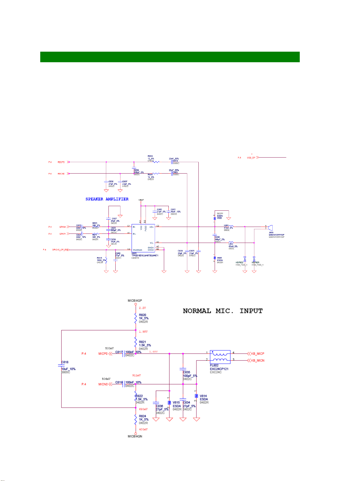
5-2-16. AUDIO SUBSYSTEM
5-2-16.1 Outline
The audio system is composed of MTK6229, PMU IC (MT6318). The attached
device is MIC, Receiver, Speaker.
5-2-16.2. Audio Control
Speaker and Receiver interface
SPEAKER interface:
Use U801 to amplify voice and voice signal from SPKN1 and SPKP1
Receiver interface:
Receiver and Microphone
The Microphone is also directly connected to MTK6229 MICIP0 and MICIN0.
KP320 SERVICE MANUAL V1.2
72
Page 74

Hands Free Interface
KP320 SERVICE MANUAL V1.2
73
Page 75

5-2-17 FM interface
MT6229 integrates a mixed-signal Baseband front-end in order to provide a wellorganized radio interface with flexibility for efficient customization. It contains gain
and offset calibration mechanisms, and filters with programmable coefficients for
comprehensive compatibility control on RF modules. This approach also allows the
usage of a high resolution D/A Converter for controlling VCXO or crystal, thus
reducing the need for expensive TCVCXO. MT6229 achieves great MODEM
in
performance by utilizing 14-bit high resolution A/D
Furthermore,
to
reduce the need for extra external current-driving component, the
Converter
the RF downlink path.
driving strength of some BPI outputs is designed to be configurable.
KP320 SERVICE MANUAL V1.2
74
Page 76
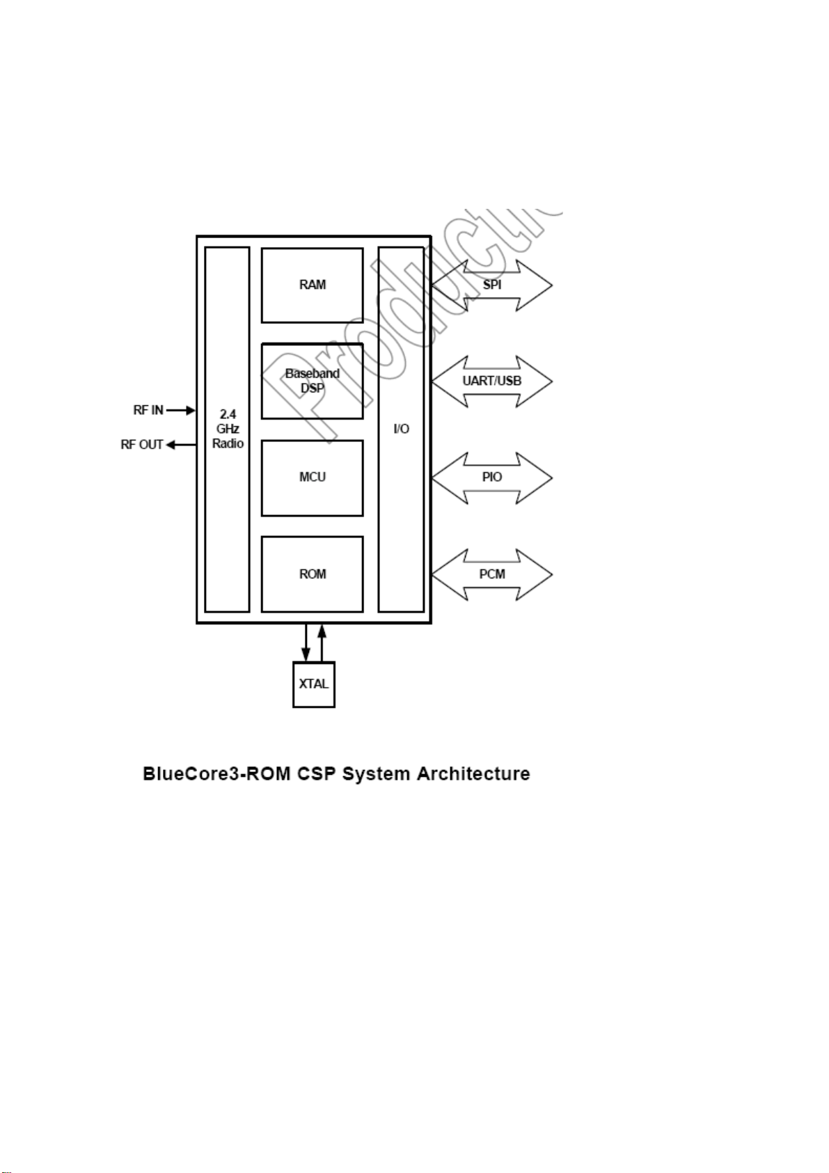
5-2-18 Bluetooth interface
BuleCore3-ROM CSP is signal chip radio and baseband chip for Bluetooth wireless
technology 2.4G Hz system .it is implemented in 0.18um CMOS technology.
The 4Mbit ROM is metal programmable ,which enables an eight week turn-around
from approval of firm are to production samples.
KP320 SERVICE MANUAL V1.2
75
Page 77

5-2-19 RF Sub-systems
KP320 SERVICE MANUAL V1.2
76
Page 78
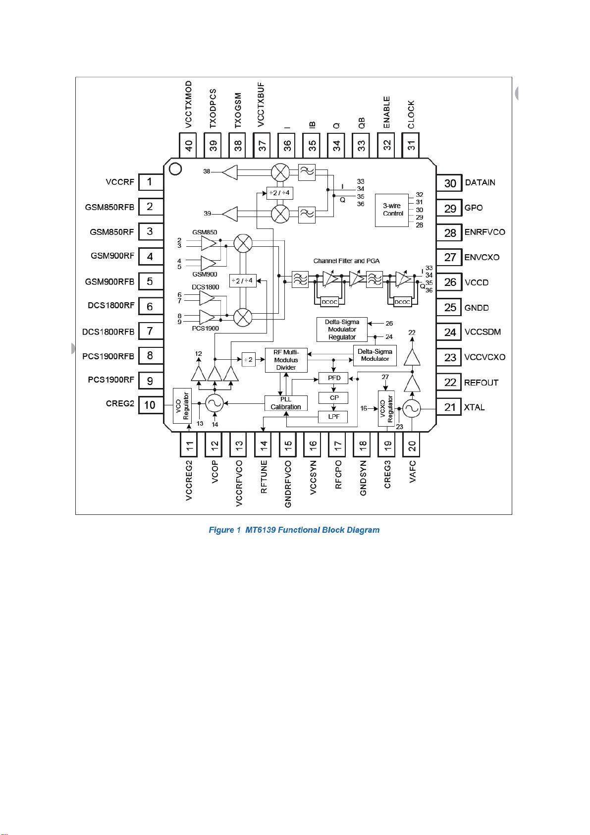
KP320 SERVICE MANUAL V1.2
77
Page 79

5-2-19.1 Receiver
KP320 SERVICE MANUAL V1.2
78
Page 80

KP320 SERVICE MANUAL V1.2
79
Page 81

<< Previous Section
Next Section >>
Main Menu
SECTION 6
6
Servicing
6-1. Structure
6-2. Accessories
6-3. Exploded Diagram
6-4. Assembly
6-5. Disassembly
6-6. Soldering
KP320 SERVICE MANUAL V1.2
80
Page 82

6-1. STRUCTURE
1. KP320
Front View Back View
KP320 SERVICE MANUAL V1.2
81
Page 83

MAIN BOARD ASSEMBLY
The lower board consists of the following circuits:-
1.Tri band GPRS GSM Transceiver and logic Unit
2.SIM connection socket
3.System I/O connector with charge capability
4.battery terminals
5.Hands free jack
6.Embedded tri band antenna connection terminal
7.Vibrator connection terminal
8.Microphone connection terminal
9.Camera connection terminal
10.Receiver connection terminal
11.Speaker connection terminal
12.SD Card connection terminal
13.LED, camera control and LCD driver circuit
14.Flash LED connector terminal
KP320 SERVICE MANUAL V1.2
82
Page 84

FRONT COVER
The Front cover contains following main parts :Keypad
2. keypad
KP320 SERVICE MANUAL V1.2
83
Page 85

REAR COVER
The Rear cover contains following main parts :-
1. Speaker
2. Vibrator
3. Flash LED label
4. Charger cover
5. SD card cover
6. Volume key
7. Camera key
Charger cover
speaker
Flash LED label
vibrator
Camera key
Volume key
75
KP320 SERVICE MANUAL V1.2
84
Page 86

6-2. ACCESSORIES
BATTERY
AC ADAPTER
KP320 SERVICE MANUAL V1.2
85
Page 87
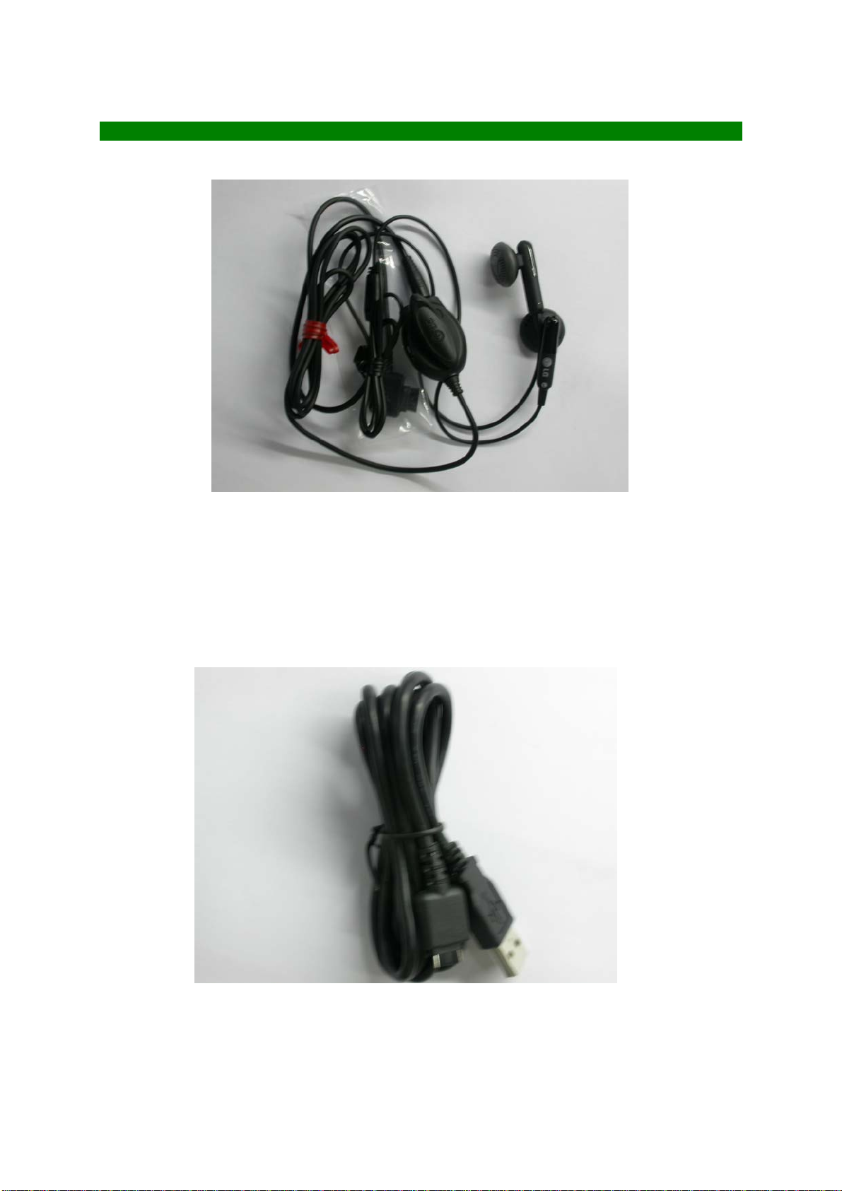
HANDSFREE & USB CABLE
Cable
KP320 SERVICE MANUAL V1.2
86
Page 88
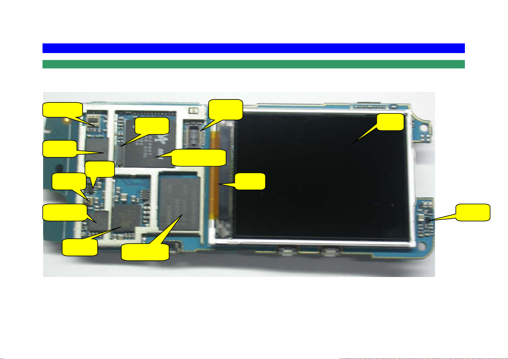
6-6. SOLDERING
SOLDERING PARTS LOCATION
SOLDERING REPAIRED PARTS AT SERVICE LEVEL 2 ARE SHOWN AS BELOW.
T/R switch
PA
SKY77318
Crystal
26 MHZ
Bluetooth
BC313141A18
PMIC
MT6318
LDO
LP3995
RTC
32.768KHz
MCP Memory
Key Board
Connector
Status
LED
Baseband Controller
MT6229
LCM
Hot Bar
FM Receiver
Si4703
KP320 SERVICE MANUAL V1.2
87
Page 89

A
ntenna
Pogo Pin
Connector
SIM Card
Micro SD
Slot
Microphone
Contact
Camera Module
connector
Vibrator
Contact
Flash LED
Pogo Pin
Battery
Contact
LDO
RT9182
Speaker
Contact
FM IC
Mini USB
Connector
RF Switch Connector
MM8430
KP320 SERVICE MANUAL V1.2
88
Page 90

TCXO
26MHz
GSM/GPRS
Transceiver
MT6139
SAW Filter
FAR-F5EB-942M50
SAW Filter
FAR-F6EB-1G8425
SAW Filter
FAR-F6EB-1G9600
95
KP320 SERVICE MANUAL V1.2
89
Page 91

<< Previous Section
Next Section >>
Main Menu
7
Section 7
Repairing
7-1. Testing
7-2. Troubleshooting
7-3. Circuit Diagrams
KP320 SERVICE MANUAL V1.2
90
Page 92

7-1. TESTING
OVERVIEW
1. Product overview and frequency assignment
TX E-GSM 880MHz to 915MHz (deltaF=200KHz)
RX E-GSM 925MHz to 960MHz (deltaF=200KHz)
Radio Frequency Band
ARFCN
RF Local Synthesizer
TX IF Frequency
Access form 8 channel multiple TDMA
Multiple 8 channel / carrier ( E-GSM/DCS1800/PCS1900)
Modulation 270.8333Kbit/s GMSK
Peak output power
Nominal supply
voltage
TX peak current 2500mA max.
GPRS Class Class10 (max 1UL/4DL) Operation class B
GPRS Coding scheme CS1/CS2/CS3/CS4
TX DCS1800 1710MHz to 1785MHz
RX DCS1800 1805MHz to 1880MHz
TX PCS1900 1850MHz to 1910MHz
RX PCS1900 1930MHz to 1990MHz
E-GSM Ful(n) = 890 + 0.2 x n at ( 0 <= n <= 124 )
Ful(n) = 880 + 0.2 x (n-1024) at ( 975 <= n <= 1023)
Fdl(n) = Ful(n) + 45
DCS1800 Ful(n) = 1710.2 + 0.2 x (n-512) at ( 512 <= n <= 885 )
Fdl(n) = Ful(n) + 95
PCS1900 Ful(n) = 1850.2 + 0.2 x (n-512) at ( 512 <= n <= 810 )
Fdl(n) = Ful(n) + 80
E-GSM 1279~1314 MHz
DCS1800 1327~1402 MHz
PCS1900 1423~1483 MHz
E-GSM 798 MHz (Typ) (880-895 MHz, 900-915 MHz)
790 MHz (Typ) (895-900 MHz)
DCS1800 766 MHz (Typ)
PCS1900 854 MHz (Typ)
E-GSM 2W(33dBm) Class4 MTS
DCS1800 1W(30dBm) Class1 MTS
PCS1900 1W(30dBm) Class1 MTS
+3.8V
2. Channel selection conditions
Verify that there is no interference from other radio devices or neighboring
measurement systems in the frequencies to be used for the test. If there is
interference, select the test channels within the range of the following channels.
Especially in case of bit error tests, make sure that there is no influence from outside
before the test. If necessary, use a shielded box or take other channel measures.
E-GSM DCS1800 PCS1900
Lch
Mch
Hch
91
975ch to 980ch 513ch to 523ch 512ch to 522ch
60ch to 65ch 690ch to 710ch 657ch to 667ch
120ch to 124ch 874ch to 884ch 800ch to 810ch
KP320 SERVICE MANUAL V1.2
Page 93

3. Product Specification
Based on GSM 11.10-1 / 3G TS 51.110
4. Measurement adapter
Dummy battery
Dummy battery should be used shown as follows:
Test SIM card
In confidence test, general Phase2 (or Phase2+) test SIM should be used.
RF connector and RF cable
RF connector and RF cable should be used for RF test
PC-Link cable
PC-link cable (Serial Link Cable) should be used.
KP320 SERVICE MANUAL V1.2
92
Page 94

FUNCTION TEST
1. Test purpose
a) To verify Appearance by visual check
b) To verify recognition of SIM card
c) To verify Function Test in the table shown as below
d) To verify power down phone
2. Test System
1. Power Supply Unit (PSU)+Dummy Battery or Battery
2. Test SIM Card (Spec: GSM Phase 2+ Test SIM Standard 1(3.1))
3. Sample Hands free Kit (SHF, Stereo)
3. Test Procedure
3.1 Appearance Test
Verify appearance by visual check
3.2 SIM Test
Verify recognition of SIM card
If “Insert SIM” indicated on Display, it is NG.
3.3 Enter Service Mode
3.1.1 No SIM Card installed
a. Power on Phone
b. Press 878 to enter service mode.
3.1.2 SIM Card installed
a. Power on Phone
b. Press *#878# to enter service mode.
3.1.3 Software Version Check
Select item 1 “Service Info” in Service mode to check software version.
KP320 SERVICE MANUAL V1.2
93
Page 95

3.4 MMI Tests
1. Auto test
2. BT Mode
3. Echo Loop
4. Version
5. Resource BIN
6. Keypad
7. Vibrator
8. Loud SPK
9. Ring Tone
10. LED
11. LCD
12. Receiver
13. ADC
14. Charger
15. Headset
16. RTC
17. MTBF
18. UART
19. Memory Card
20. Nand Flash
21. Camera
22. Total call time
23.
FM Radio
KP320 SERVICE MANUAL V1.2
94
Page 96

1. Test purpose
This test is for check RF characteristics.
2. Test system
1. PC
2. Printer
3. PSU
4. GSM Test Set
5. USB Cable
6. UART Cable
7. Calibration Adapter
8. RF Cable
Measurement setup is shown as follows:
Test Instruments
1. PC
2. PRINTER
CONFIDENCE TEST
5. USB Cable
6. UART Cable
4. GSM Test Set
E5515B
(HP8960)
Calibration adapter
Lower
Board
8. RF Cable
3. PSU
HPE3631A
KP320 SERVICE MANUAL V1.2
95
Page 97

3. Test Specification
Measurement item and specification is defined as follows:
Test Item
TX Maximum Power
TX Power
RMS Phase error
PEAK Phase error
Frequency Error
Power Vs Time
RX Class2 RBER
RX Level
RX Quality
31dBm +/- 3dB @ PL6
29dBm +/- 3dB @ PL7
27dBm +/- 3dB @ PL8
25dBm +/- 3dB @ PL9
23dBm +/- 3dB @ PL10
21dBm +/- 3dB @ PL11
19dBm +/- 3dB @ PL12
17dBm +/- 3dB @ PL13
15dBm +/- 3dB @ PL14
13dBm +/- 3dB @ PL15
11dBm +/- 5dB @ PL16
9dBm +/- 5dB @ PL17
7dBm +/- 5dB @ PL18
5dBm +/- 5dB @ PL19
pass/fail indication. Detail specification is shown as table 4.1
Specification
E-GSM DCS1800 PCS1900
33dBm +/-2dB 30dBm +/-2dB
28dBm +/- 3dB @ PL1
26dBm +/- 3dB @ PL2
24dBm +/- 3dB @ PL3
22dBm +/- 3dB @ PL4
20dBm +/- 3dB @ PL5
18dBm +/- 3dB @ PL6
16dBm +/- 3dB @ PL7
14dBm +/- 3dB @ PL8
12dBm +/- 4dB @ PL9
10dBm +/- 4dB @ PL10
8dBm +/- 4dB @ PL11
6dBm +/- 4dB @ PL12
4dBm +/- 4dB @ PL13
2dBm +/- 5dB @ PL14
0dBm +/- 5dB @ PL15
<5deg
<20deg
< 90Hz < 180Hz < 185Hz
<2.4% @ -103.5dBm (avg 10000bit)
7 +/-4 @ -103.5dBm
<3 @ -103.5dBm
KP320 SERVICE MANUAL V1.2
96
Page 98

(*)
(**)
(***)
Power Vs Time mask specification
dB
+ 4
+ 1
- 1
- 6
(**)
- 30
(***)
(147 bits)
(*)
8
탎
10
탎
10
탎
7056/13 (542.8)
10 탎8
탎
탎
10
탎
t
Time mask for normal duration bursts(NB,FB,dB and SB) at GMSK modulation
For GSM 900 MS : -59 dBc or -54 dBm, whichever is the
greater, except for the time slot
preceding the active slot, for which
the allowed level is -59 dBc
or -36 dBm whichever is the greater
For DCS1800 and PCS1900 MS : -48 dBc or -48 dBm, whichever is the
higher.
For GSM 900 MS :
-4 dBc for power control level 16;
-2 dBc for power level 17;
-1 dBc for power level controls levels
18 and 19.
For DCS1800 and PCS1900 MS :
-4dBc for power control level 11,
-2dBc for power level 12,
-1dBc for power control levels 13,14
and 15
For GSM 900 MS : -30 dBc or -17 dBm, whichever is the
higher.
For DCS1800 and PCS1900 MS : -30dBc or -20dBm, whichever is the
higher.
KP320 SERVICE MANUAL V1.2 97
Page 99

4. Test Procedure
Test items should be sequential in the table shown as below. Due to limitation of
GSM test set, the test should be started under E-GSM mode and hand over to DCS1800.
In PCS1900 mode, the test should be started under PCS1900 mode.
Default setting of GSM test set and PSU is shown as follows:
(Internal Loss) (Please measure cable loss on first set-up and calibrate
it.)
CALL STATUS IDLE
CELL STATUS ACTIVE CELL
OPERATING MODE E-GSM
Expected input level TX Level 5 : 33dBm
Control Base station Broadcast Broadcast ON
Control Base station Channel 20
Control Base station Amplitude -85dBm
Mobile Phone Channel 62 ( could be changed ARFCN Mch )
Mobile Phone TX Level 5
Mobile Phone Timeslot 4
PSU output voltage +3.8V +/- 0.05V
PSU maximum current limit 2500mA
CALL STATUS IDLE
CELL STATUS ACTIVE CELL
OPERATING MODE PCS1900
Expected input level TX Level 0 : 30dBm
Control Base station Broadcast Broadcast ON
Control Base station Channel 512
Control Base station Amplitude -85dBm
Mobile Phone Channel 661 ( could be changed ARFCN Mch )
Mobile Phone TX Level 0
Mobile Phone Timeslot 4
PSU output voltage +3.8V +/- 0.05V
PSU maximum current limit 2800mA
KP320 SERVICE MANUAL V1.2 98
Page 100

Test item MODE Procedure
Start up
E-GSM 1. Set SIM card and dummy battery to HHP
2. Power on HHP
3. Wait to indicate “GSM Test Net 001”
Call setup
TX Power
RMS Phase error
PEAK Phase error
Frequency Error
Power Vs Time
RX Class2 RBER
RX Level
RX Quality
Hand over
Close down
*1 Refer to 1.Overview Channel selection condition
E-GSM 1. Input the PTE command “StartCall”
2. Input the PTE command “Receivecall”.
3. Wait to indicate “Active” to establish call
E-GSM
DCS1800
E-GSM
DCS1800
E-GSM
DCS1800
E-GSM
DCS1800
E-GSM
DCS1800
E-GSM
DCS1800
E-GSM
DCS1800
E-GSM
DCS1800
E-GSM to
DCS1800
( Test is repeated under DCS1800 band )
DCS1800 1. Push “END Call” of GSM tester
1. ARFCN is assign to Mch ( and Lch/Hch )
2. Set PL to 5(E-GSM) or 0(DCS1800)
3. Wait to establish hand over
4. Measure output power
1. ARFCN is assigned to Mch ( or Lch/Hch )
2. Set PL to 5(E-GSM) or 0(DCS1800)
3. Wait to establish hand over
4. Change mode of GSM tester to “Phase/FREQ”
5. Set analyze burst number to 50
6. Read “RMS maximum” window
1. ARFCN is assigned to Mch ( or Lch/Hch )
2. Set PL to 5(E-GSM) or 0(DCS1800)
3. Wait to establish hand over
4. Change mode of GSM tester to “Phase/FREQ”
5. Set analyze burst number to 50
6. Read “PEAK maximum” window
1. ARFCN is assigned to Mch ( or Lch/Hch )
2. Set PL to 5(E-GSM) or 0(DCS1800)
3. Wait to establish hand over
4. Change mode of GSM tester to “Phase/FREQ”
5. Set analyze burst number to 50
6. Read “Frequency error maximum” window
1. ARFCN is assigned to Mch
2. Set PL to 5(E-GSM) or 0(DCS1800)
3. Wait to establish hand over
4. Change mode of GSM tester to “Power Ramp”
5. To check pass/fail indication under three mode “TOP 2dB”
“Rise edge” and “Fall edge”
1. ARFCN is assigned to Mch*1
2. Set PL to 5(E-GSM) or 0(DCS1800)
3. Wait to establish hand over
4. Change mode of GSM tester to “Bit error”
5. To define sampling value to 10000
6. To define measure “Res Type 2”
7. To adjust base station output level to -103.5dBm
8. Wait to indicate BE Ratio and read it.
1. Same setting and procedure as RX RBER
2. Wait to indicate “Mobile reported Rxlev” and read it.
1. Same setting and procedure as RX RBER
2. Wait to indicate “Mobile reported RX Qual” and read it.
1. Change mode of GSM tester to “DUAL BAND”
2. To define DCS1800 parameter. ARFCN to Mch, Base station
output level to –85dBm, Mobile power level to PL0.
3. Push “Execute” and check establish hand over.
2. Wait to indicate “Call End” and change to idle screen.
3. Push “Power” to check shut down.
KP320 SERVICE MANUAL V1.2 99
 Loading...