

Lg Acq058pl, Hblg5200e, Hblg6000r, Kg5200er, Acq052pk Owner's Manual
...
LG
Room
Air Conditioner
SERVICE MANUAL
LG
MODEL: ACQ058PL LW7000R
KG5200ER WM-5031
LW5200ER LW050CE
WG5200ER LWJ0515PAG
WG6000R LW5200R
KG6000R
M5404R
WG5200R
M6004R
HBLG6000R
HBLG5200E
ACQ052PK
CAUTION
website http://www.lgservice.com
• BEFORE SERVICING THE UNIT, READ THE SAFETY
PRECAUTIONS IN THIS MANUAL.
• ONLY FOR AUTHORIZED SERVICE PERSONNEL.

CONTENTS
1. PREFACE ....................................................................................................................................................................... 2
1.1 FEATURES ........................................................................................................................................................................ 2
1.2 SPECIFICATIONS ............................................................................................................................................................. 3
1.3 SAFETY PRECAUTIONS ................................................................................................................................................. 3
1.4 INSULATION RESISTANCE TEST .................................................................................................................................... 3
1.5 LOCATIONS OF CONTROLS ........................................................................................................................................... 4
2. DISASSEMBLY INSTRUCTIONS .................................................................................................................... 6
2.1 MECHANICAL PARTS ...................................................................................................................................................... 6
2.1.1 FRONT GRILLE ....................................................................................................................................................... 6
2.1.2 CABINET................................................................................................................................................................... 6
2.1.3 CONTROL BOARD ................................................................................................................................................... 6
2.2 AIR HANDLING PARTS .................................................................................................................................................... 7
2.2.1 AIR GUIDE UPPER................................................................................................................................................... 7
2.2.2 ORIFICE, TURBO FAN AND FAN............................................................................................................................. 7
2.2.3 MOTOR .................................................................................................................................................................... 8
2.2.4 AIR GUIDE ................................................................................................................................................................ 8
2.3 ELECTRICAL PARTS ....................................................................................................................................................... 8
2.3.1 OVERLOAD PROTECTOR ...................................................................................................................................... 8
2.3.2 COMPRESSOR ........................................................................................................................................................ 9
2.3.3 CAPACITOR ............................................................................................................................................................. 9
2.3.4 THERMISTOR........................................................................................................................................................... 9
2.3.5 CONTROL PANEL..................................................................................................................................................... 9
2.3.6 POWER CORD ...................................................................................................................................................... 10
2.4 REFRIGERANT CYCLE ............................................................................................................................................ 10
2.4.1 CONDENSER ........................................................................................................................................................ 10
2.4.2 EVAPORATOR ....................................................................................................................................................... 10
2.4.3 CAPILLARY TUBE ................................................................................................................................................. 11
3. INSTALLATION ......................................................................................................................................................... 13
3.1 SELECT THE BEST LOCATION ..................................................................................................................................... 13
3.2 HOW TO INSTALL .......................................................................................................................................................... 13
ELECTRICAL DATA
3.3
4. TROUBLESHOOTING GUIDE ........................................................................................................................
4.1 OUTSIDE DIMENSIONS ................................................................................................................................................. 16
4.2 PIPING SYSTEM ............................................................................................................................................................ 17
4.3 TROUBLESHOOTING GUIDE ........................................................................................................................................ 18
..................................................................................................................................................... 16
16
5. SCHEMATIC DIAGRAM ...................................................................................................................................... 26
5.1 CIRCUIT DIAGRAM......................................................................................................................................................... 26
5.2 ELECTRONIC CONTROL DEVICE ................................................................................................................................. 27
5.3
COMPONENTS LOCATION(FOR MAIN P.W.B ASM)
5.4
COMPONENTS LOCATION(FOR DISPLAY P.W.B ASM)
............................................................................................................... 28
......................................................................................................... 28
6. EXPLODED VIEW ................................................................................................................................................... 29
7. SPECIFICATION AND PARTS LIST ............................................................................................................ 30
—2—
1. PREFACE
This service manual provides various service information, including the mechanical and electrical parts, etc.
This room air conditioner was manufactured and assembled under a strict quality control system.
The refrigerant is charged at the factory. Be sure to read the safety precautions prior to servicing the unit.
1.1 FEATURES
• DESIGNED FOR COOLING ONLY
• POWERFUL AND INCREDIBLE COOLING
• TOP-DOWN CHASSIS FOR THE SIMPLE INSTALLATION AND SERVICE
• WASHABLE ONE-TOUCH FILTER
• COMPACT SIZE
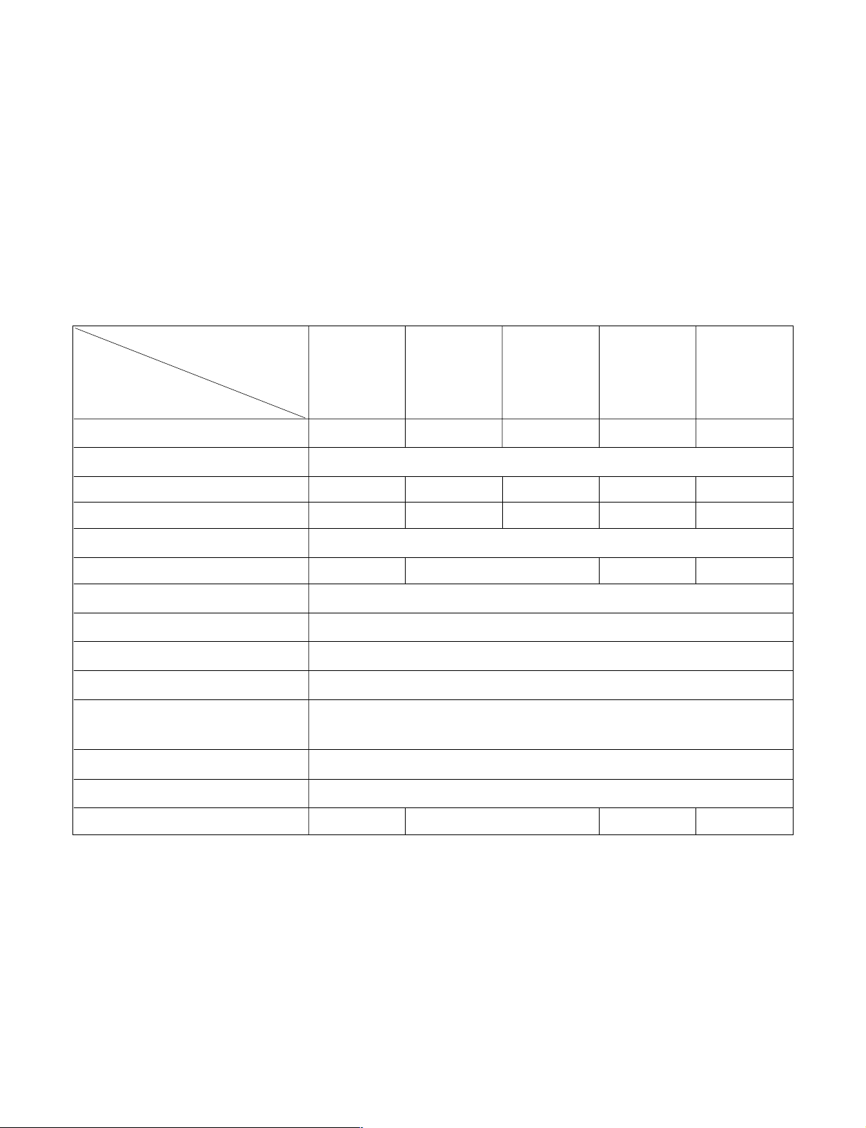
1.2 SPECIFICATIONS
ITEMS
MODELS
WG5200ER,
LW5200ER,
HBLG5200E,
LWC051JGMK2
KG5200ER
ACQ058PL
LW050CE
WG5200R
ACQ052PK
M5404R
WM5031
LWJ0515PAG
LW5200R
WG6000R
M6004R
KG6000R
HBLG6000R
LW7000R
COOLING CAPACITY (BTU/h)
POWER SUPPLY (Phase, V, Hz)
INPUT (W)
OPERATING CURRENT (AMP.)
REFRIGERANT CONTROL
REFRIGERANT CHARGE (R-22)
INSIDE FAN
OUTSIDE FAN
AIR DISCHARGE
CHASSIS
PROTECTOR
TEMPERATURE CONTROL
ROTARY SWITCH
FAN MOTOR
5,200 5,050 5,250 6,000 76,000
1ø, 115V, 60HZ
470/480 520 540 620 720
4.3/4.4 4.8 5.0 5.8 6.7
CAPILLARY TUBE
330g (11.6 Oz) 220g(7.8 Oz) 235g (8.3 Oz) 315g (11.1 Oz)
TURBO
PROPELLER FAN WITH SLINGER RING
2-WAY (RIGHT AND LEFT)
TOP-DOWN
• OVERLOAD PROTECTOR FOR COMPRESSOR
• INTERNAL PROTECTOR FOR FAN MOTOR
THERMISTOR
5 POSITIONS (LOW FAN, HIGH FAN, OFF, HIGH COOL, LOW COOL)
6 POLES, 21W 6 POLES, 19W 6 POLES, 21W 6 POLES, 27W
• NOTE: Specifications are subject to minor change without notice for further improvement.
1.3 SAFETY PRECAUTIONS
1. When servicing, set the POWER of CONTROL
BOARD to Off and unplug the power cord.
2. Observe the original lead dress.
If a short circuit is found, replace all parts which
have been overheated or damaged by the short circuit.
3. After servicing, make an insulation resistance test
to prevent the customer's exposure to shock
hazards.
1.4
INSULATION RESISTANCE TEST
1. Unplug the power cord and connect a jumper
between 2 pins (black and white).
2. The grounding conductor (green or green and yellow) is to be open.
3. Measure the resistance value with an ohm meter
between the jumpered lead and each exposed
metallic part on the equipment at all Mode [except
POWER OFF].
4. The value should be over 1 MΩ.
—3—
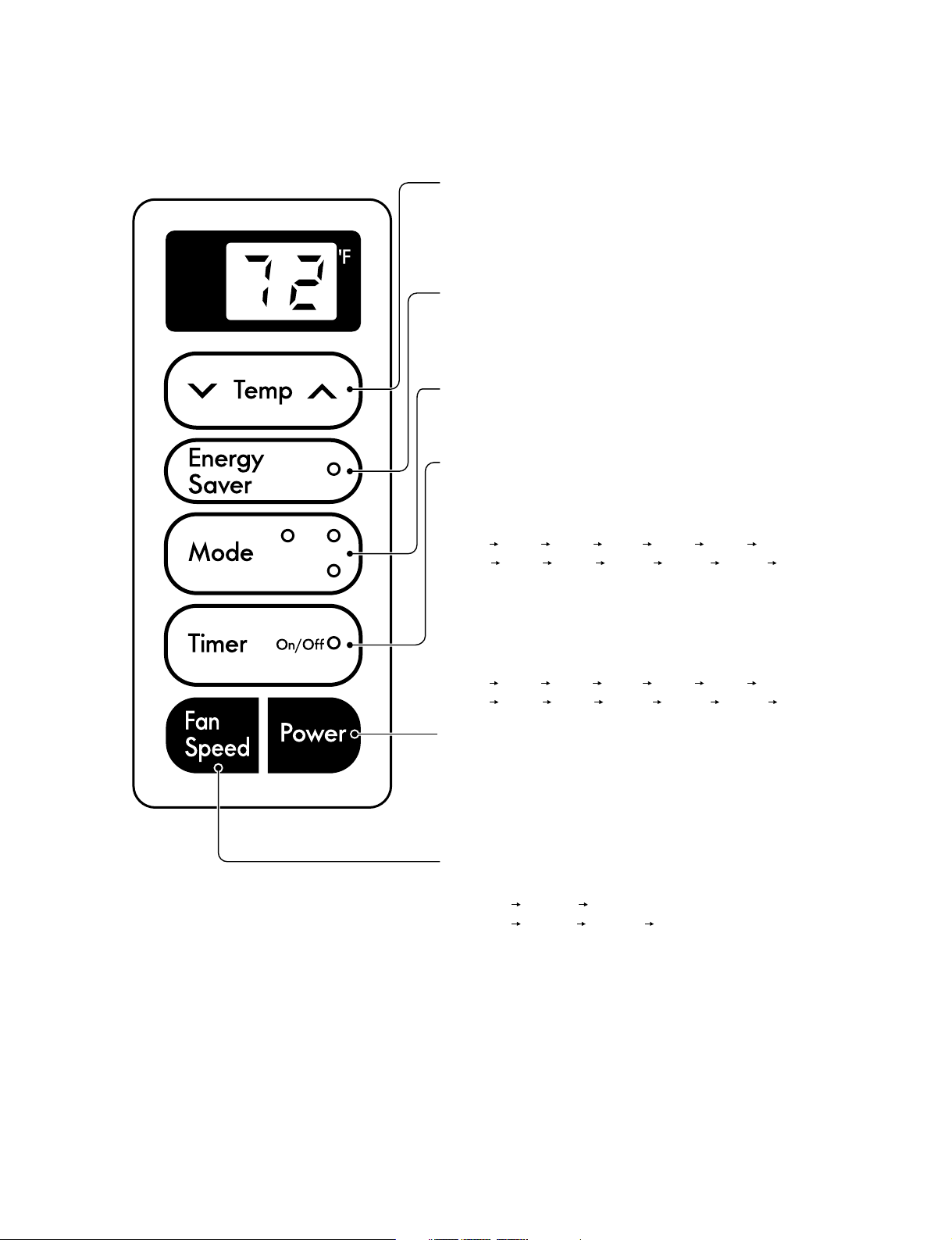
1.5 LOCATIONS OF CONTROLS
Dry Fan
Cool
ON/OFF TIMER
- STOPPING OPERATION
• Everytime you push this button, when the unit is operating,
timer is set as follows.
(1Hour 2Hours 3Hours 4Hours 5Hours 6Hours
7Hours 8Hours 9Hours 10Hours 11Hours 12Hours Cancel)
• The Setting Temperature will be raised by 2°F(1°C) 30min. later
and by 2°F(1°C) after another 30 min.
- STARTING OPERATION
• Everytime you push this button, when the unit is
not operating, timer is set as follow.
(1Hour 2Hours 3Hours 4Hours 5Hours 6Hours
7Hours 8Hours 9Hours 10Hours 11Hours 12Hours Cancel)
MODE
• Everytime you push this button, it will toggle between
COOL, FAN, DRY or FAN, COOL.
POWER
• To turn the unit ON, push the button. To turn the unit OFF,
push the button again.
• This button takes priority over any other buttons.
• When you first turn it on, the unit is on the High cool mode
and the temp. at 72°F(22°C).
TEMPERATURE SETTING
• This button can automatically control the temperature
of the room. The temperature can be set within a range of
60°F(16°C) to 86°F(30°C) by 1°F(1°C).
Select the lower number for lower temperature of the room.
FAN SPEED
• Everytime you push this button it is set as follows.
{High(F2) Low(F1) High(F2)...} or
{High(F3) Mid(F2) Low(F1) High(F3)...}.
ENERGY SAVER
The fan stops when the compressor stops cooling.
• Approximately every 3 minutes the fan will turn on and
check the room air to determine if cooling is needed.
1.5.1
CONTROLS
—4—
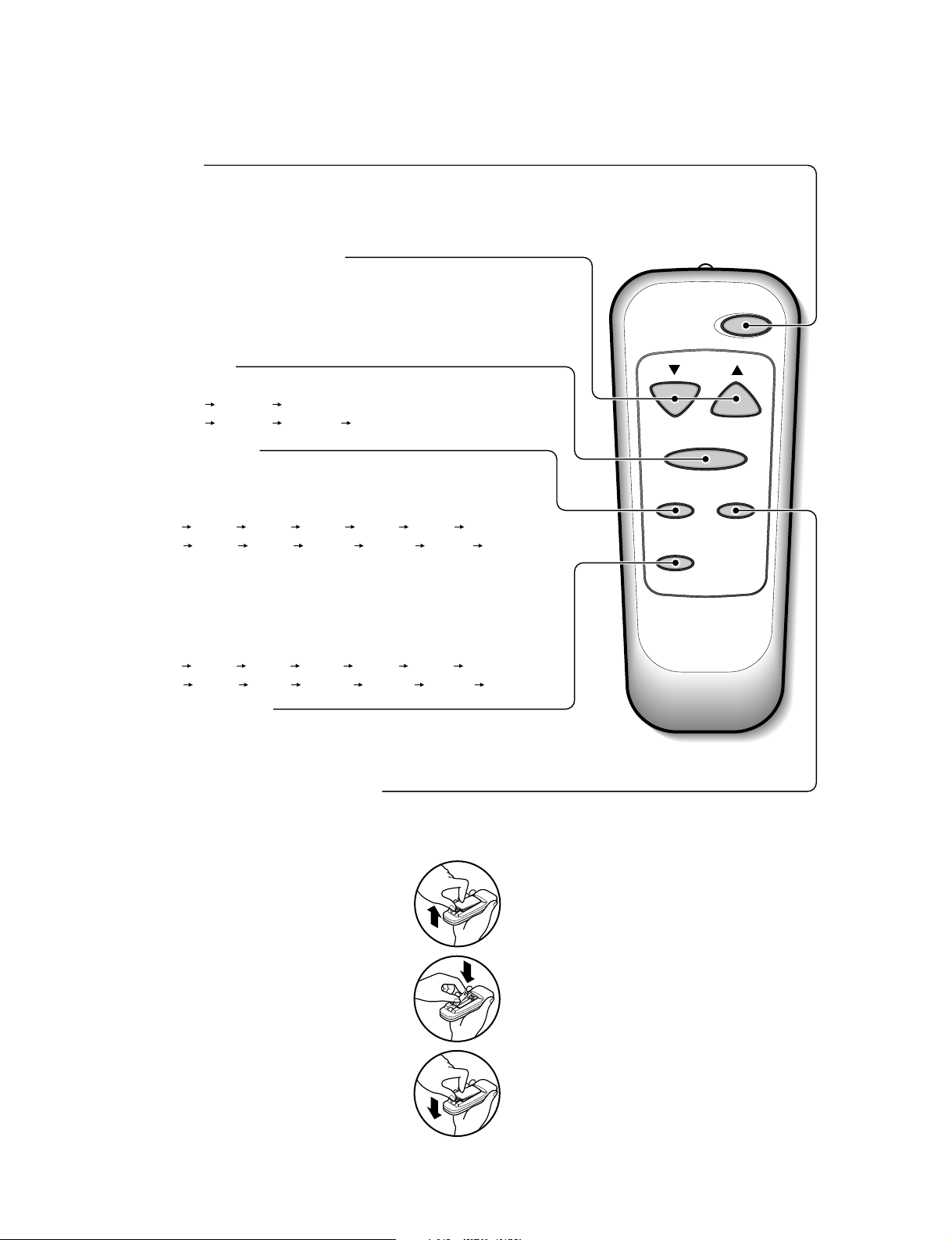
1.5.2 REMOTE CONTROLLER
Auto
Swing
Power
Temp
Fan Speed
Timer Mode
Energy
Saver
TEMPERATURE SETTING
ENERGY SAVER
The fan stops when the compressor stops cooling.
• Approximately every 3 minutes the fan will turn on and
check the room air to determine if cooling is needed.
FAN SPEED
• Everytime you push this button it is set as follows.
{High(F2) Low(F1) High(F2) or
{High(F3) Mid(F2) Low(F1) High(F3)...}
POWER
• To turn the Set ON, push the button. To turn the Set OFF, push the button again.
• This button takes priority over any other buttons.
• When you first turn it on, the Set is on the High cool mode and the temp. at 72°F(22°C).
COOL/FAN/DRY or COOL/FAN
• Everytime you push this button, it will toggle between COOL, FAN and DRY.
ON/OFF TIMER
- STOPPING OPERATION
• Everytime you push this button, when the set is operating,
timer is set as follows.
(1Hour 2Hours 3Hours 4Hours 5Hours 6Hours
7Hours 8Hours 9Hours 10Hours 11Hours 12Hours Cancel)
• The Setting Temperature will be raised by 2°F(1°C) 30min.
later and by 2°F(1°C) after another 30 min.
- STARTING OPERATION
• Everytime you push this button, when the set is
not operating, timer is set as follow.
(1Hour 2Hours 3Hours 4Hours 5Hours 6Hours
7Hours 8Hours 9Hours 10Hours 11Hours 12Hours Cancel)
• This button can automatically control the temperature of the room.
The temperature can be set within a range of
60°F(16°C) to
86°F(30°C) by 1°F(1°C).
Select the lower number for lower temperature of the room.
How to Insert Batteries
1. Remove the cover from the back of the
remote controller
2. Insert two batteries.
• Be sure that the (+) and (-) directions
are correct.
• Be sure that both batteries are new.
3. Re-attach the cover.
• Do not use rechargeable batteries. Such batteries
differ from standard dry cells in shape, dimensions, and performance.
• Remove the batteries from the remote controller if the air conditioner is not going to be
used for an extended length of time.
—5—
2. DISASSEMBLY INSTRUCTIONS
2.1 MECHANICAL PARTS
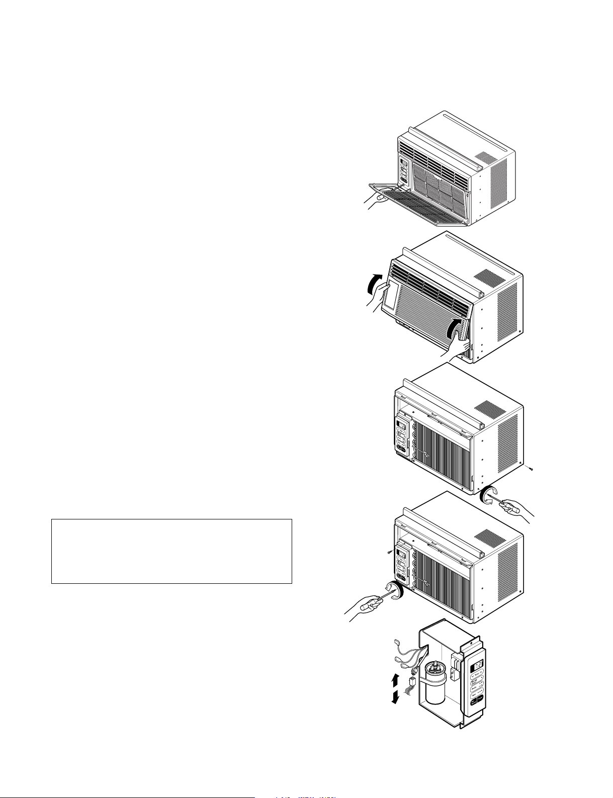
2.1.1 FRONT GRILLE
1. Disconnect the unit from source of power.
2. Using a screwdriver, remove the screw that
secures the front grille to control board.
(See Figure 1)
3. Push the front grille up from the bottom.
Pull the top of the front grille away from the
cabinet as the top tabs lift out of their slots.
(See Figure 2)
4. Replace the grille by placing the tabs in the slots
and push the grille until it snaps into place.
2.1.2 CABINET
1. Disconnect the unit from the power source.
2. Remove the front grille. (Refer to section 2.1.1)
3. Remove 9 screws that secure the cabinet to the
base pan and condenser. (See Figure 3)
4. Lift the cabinet from the unit.
5. Re-install by referring to the procedures above.
Figure 1
Figure 2
Figure 3
2.1.3 CONTROL BOARD
1. Disconnect the unit from the power source.
2. Remove the front grille. (Refer to Section 2.1.1)
3. Remove the cabinet. (Refer to Section 2.1.2)
4. Remove 2 screws that secure the control board to
base pan and air guide. (See Figure 4)
5. Pull the control board toward yourself.
NOTE : Controls, wires, and capacitor are now
accessible for servicing. Discharge the
capacitor before servicing. See step
2.3.3 on page 9 for procedures.
6. Disconnect one housing terminal and 3 wires for
the fan motor and compressor. (See Figure 5)
7. Re-install components by referring to procedures
above. (Refer to circuit diagram on page 26 in this
manual or inside control board.)
Figure 4
Figure 5
—6—
2.2 AIR HANDLING PARTS
2.2.1 AIR GUIDE UPPER
1. Disconnect the unit from the power source.
2. Remove the front grille. (Refer to Section 2.1.1)
3. Remove the cabinet. (Refer to Section 2.1.2)
4. Remove the control board.
(Refer to Section 2.1.3)
5. Remove 2 screws that secure the brace to air
guide upper and shroud. (See Figure 6)
6. Remove 2 screws that secure the air guide upper
to air guide lower. (See Figure 6)
7. Lift air guide upper upward.
8. Re-install by referring to the procedures above.
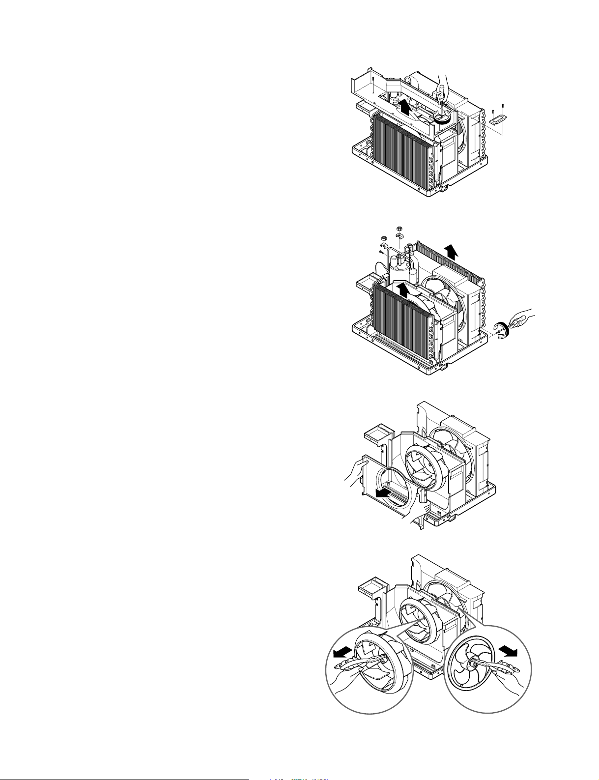
2.2.2 ORIFICE, TURBO FAN AND FAN
1. Disconnect the unit from the power source.
2. Remove the front grille. (Refer to Section 2.1.1)
3. Remove the cabinet. (Refer to Section 2.1.2)
4. Remove the control board.
(Refer to Section 2.1.3)
5. Remove the air guide upper.
(Refer to Section 2.2.1)
6. Remove 2 screws that secure the base pan to
condenser. (See Figure 7)
7. Remove 2 screws that secures the shroud to
channel of condenser.
8. Press the snap area of shroud with your thumbs.
This allows you to remove it from the condenser.
9. Lift the compressor upward with the evaporator
and condenser. (See Figure 7)
10. Remove the orfice by pushing the snap area of
the air guide blower. (See Figure 8)
11. Remove the clamp springs which are clamped to
the boss of fan and turbo fan by hand plier. (See
Figure 9)
12. Pull the fan and turbo fan outward.
13. Remove the shroud.
14. Re-install by referring to the procedures above.
Figure 6
Figure 7
Figure 8
Figure 9
—7—
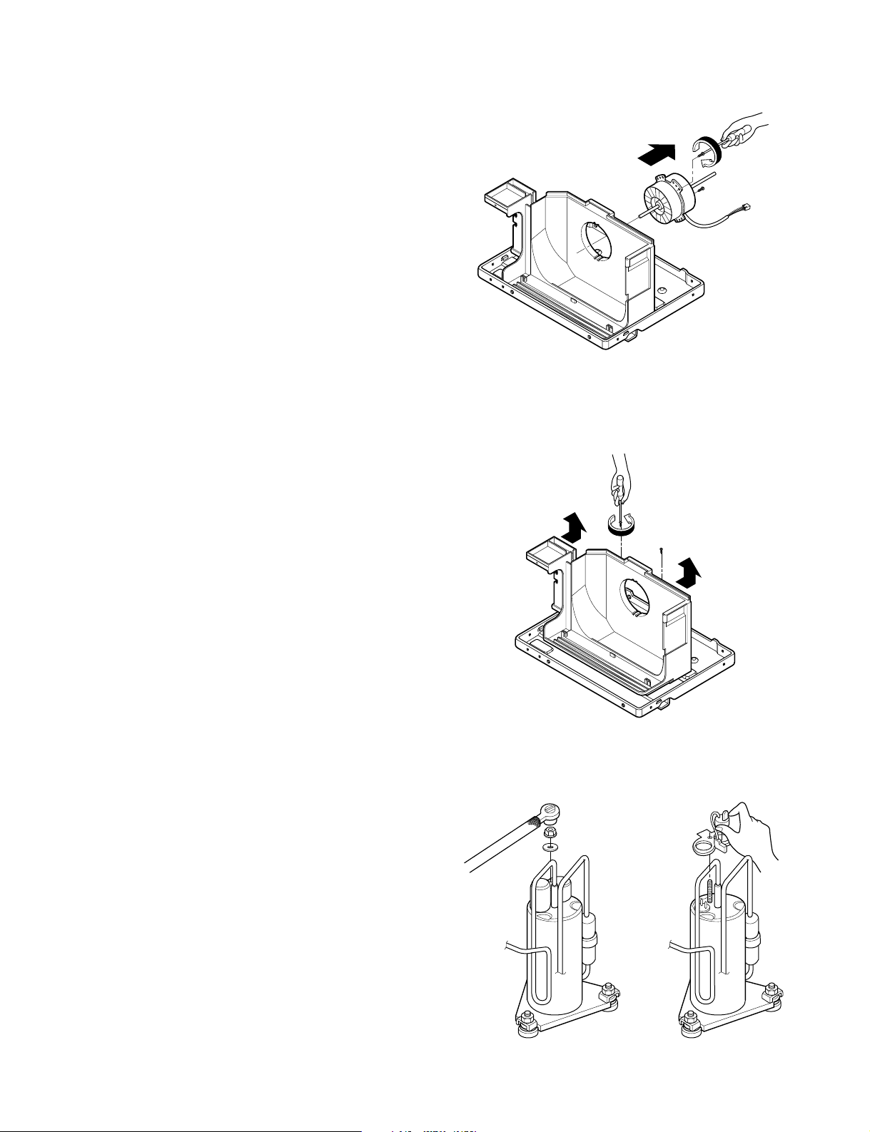
2.2.3 MOTOR
1. Disconnect the unit from the power source.
2. Remove the front grille. (Refer to Section 2.1.1)
3. Remove the cabinet. (Refer to Section 2.1.2)
4. Remove the control board.
(Refer to Section 2.1.3)
5. Remove the air guide upper.
(Refer to Section 2.2.1)
6.
Remove the compressor, turbo fan, fan and
shroud. (Refer to
7.
Remove 2 screws that secure the motor to the
motor. (See Figure 10)
8. Remove the motor.
9.
Re-install by referring to the procedures above.
Section
2.2.2)
Figure 10
2.2.4 AIR GUIDE
1. Disconnect the unit from the power source.
2. Remove the front grille. (Refer to Section 2.1.1)
3. Remove the cabinet. (Refer to Section 2.1.2)
4. Remove the control board.
(Refer to Section 2.1.3)
5. Remove the air guide upper.
(Refer to Section 2.2.1)
6.
Remove the compressor, turbo fan, fan and
shroud. (Refer to
7.
Remove the motor. (Refer to
8. Remove 2 screws that secure the air guide to the
base pan. (See Figure 11)
9. Push the air guide backward and lift it upward.
(See Figure 11)
10. Re-install by referring to the procedures above.
Section
2.2.2)
Section
2.2.3)
2.3 ELECTRICAL PARTS
2.3.1 OVERLOAD PROTECTOR
1. Remove the front grille and cabinet.
(Refer to Section 2.1)
2. Remove the nut which fastens the terminal cover.
3. Remove the terminal cover.
4. Remove all the leads from the overload protector.
5. Remove the overload protector.
6. Re-install the components by referring to the
removal procedure above.
(See Figure 12 and 13)
Figure 11
Figure 12
Figure 13
—8—
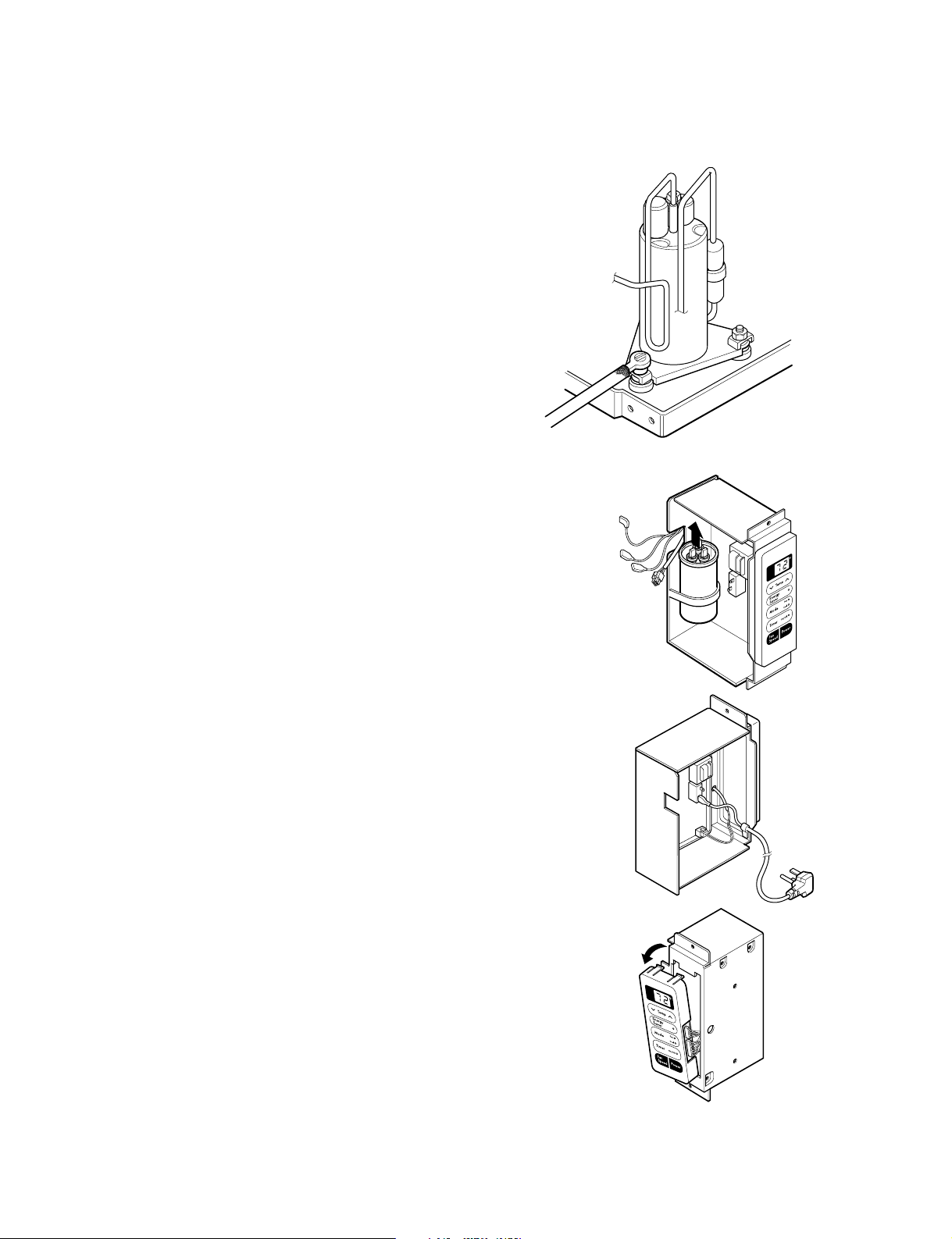
2.3.2 COMPRESSOR
1. Remove the front grille and cabinet.
(Refer to Section 2.1.2)
2. Discharge the refrigerant by using a refrigerant
recovery system.
3. Remove the overload protector.
(Refer to Section 2.3.1)
4. After discharging the unit completely, unbrace the
suction and discharge pipes at the compressor
connections.
5. Remove 3 nuts which fasten the compressor.
6. Remove the compressor.
7. Re-install by referring to the removal procedure
above. (See Figure 14)
2.3.3 CAPACITOR
1. Remove the cabinet. (Refer to Section 2.1.2)
2. Remove the control board.
(Refer to Section 2.1.3)
3. Discharge the capacitor by placing a 20 KΩ
resistor across the capacitor terminals.
4. Pull the capacitor upward.
5. Remove all the leads of capacitor terminals.
6. Re-install the components by referring to the
removal procedure above. (See Figure 15)
Figure 14
Figure 15
2.3.4 THERMISTOR
1. Remove the cabinet. (Refer to Section 2.1.2)
2. Remove the control board.
(Refer to Section 2.1.3)
3. Disconnect the thermistor terminals from main
P.W.B assembly.
4. Remove the thermistor.
5. Re-install the components by referring to the
removal procedure above. (See Figure 16)
2.3.5 CONTROL PANEL
1. Remove the cabinet. (Refer to Section 2.1.2)
2. Remove the control board.
(Refer to Section 2.1.3)
3. Pull the control panel forward and pull out it.
4. Remove 2 lead wire terminals.
5. Re-install the components by referring to the
removal procedure above. (See Figure 17)
Figure 16
Figure 17
—9—
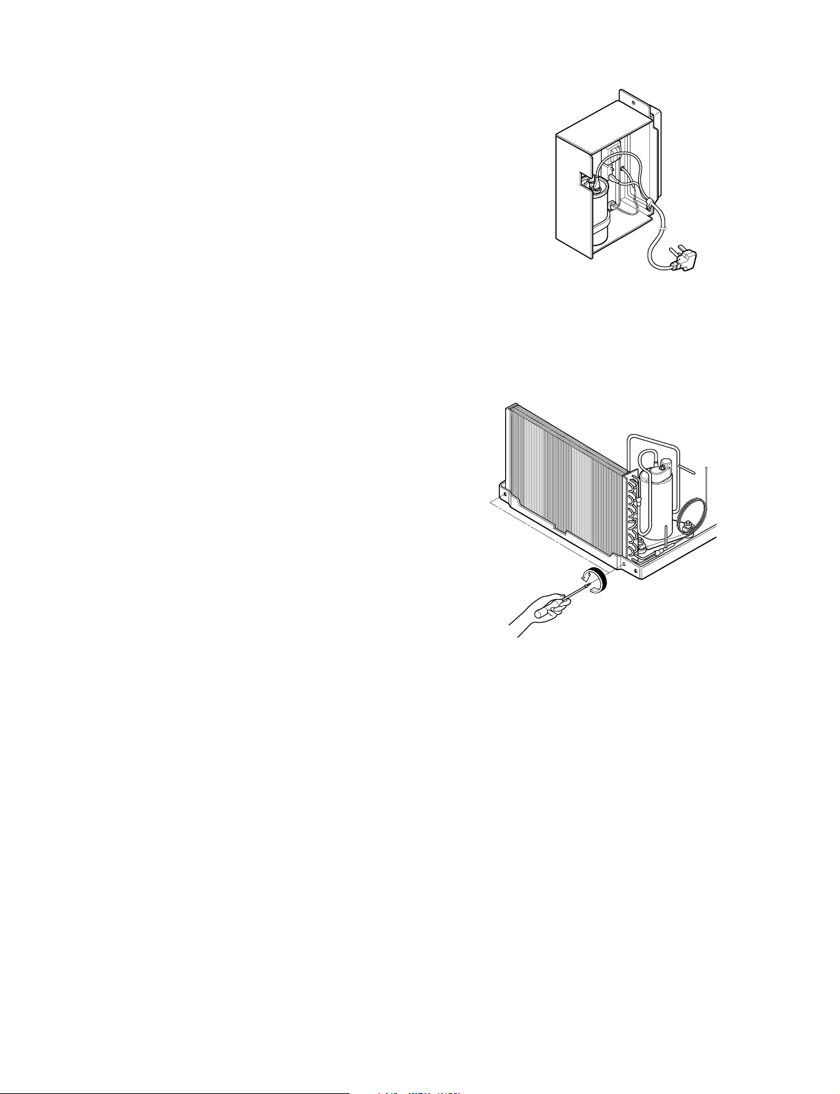
2.3.6 POWER CORD
1. Disconnect the unit from source of power.
2. Remove the front grille. (Refer to Section 2.1.1)
3. Remove the cabinet. (Refer to Section 2.1.2)
4. Remove 2 screws that secure control board to
base pan and air guide. (Refer to Section 2.1.3)
5. Pulls the control board toward you.
6. Remove the grounding screw.
7. Remove a screw securing the clip with cord to the
control board.
8. Pull the power cord.
9. Re-install by referring to procedures above.
Figure 18
2.4 REFRIGERANT CYCLE
2.4.1 CONDENSER
1. Remove the cabinet. (Refer to Section 2.1.2)
2. Discharge the refrigerant by using a refrigerant
recovery system.
3. Remove 2 screws which fasten the condenser.
(See Figure 19)
4. After discharging the refrigerant completely,
unbraze the interconnecting tube at the
condenser connections.
5. Remove the condenser.
6. Re-install by referring to the procedures above.
2.4.2 EVAPORATOR
1. Remove the cabinet. (Refer to Section 2.1.2)
2. Discharge the refrigerant by using a refrigerant
recovery system.
3. Remove the air guide upper. (Refer to Section
2.2.1)
4. After discharging the refrigerant completely,
unbraze the interconnecting tube at the evaporator
connections.
5. Remove the evaporator.
6. Re-install by referring to the procedures above.
Figure19
—10—

2.4.3 CAPILLARY TUBE
1. Remove the cabinet. (Refer to Section 2.1.2)
2. Discharge the refrigerant by using a refrigerant
recovery system.
3. Remove the air guide upper. (Refer to Section
2.2.1)
4. After discharging the refrigerant completely,
unbraze the interconnecting tube of the capillary
tube.
5. Remove the capillary tube.
6. Re-install by referring to the procedures above.
NOTES
Replacement of the refrigeration cycle.
1. When replacing the refrigerating cycle, be sure to
discharge the refrigerant by using a refrigerant
recovery system.
2. After discharging the unit completely, remove the
desired components, and unbraze the pinch-off
tubes.
3. Solder service valves into the pinch-off tube ports,
leaving the valves open.
4. Solder the pinch-off tubes with service valves.
5. After completing the above procedures, the valve
must be closed and left in place on the system for
any subsequent procedures.
6. Evacuate as follows:
6-1. Connect the vacuum pump, as illustrated in
figure 20A.
6-2. Start the vacuum pump. Slowly open manifold
valves A and B with two full turns counterclockwise and leave the valves closed.
The vacuum pump is now pulling through
valves A and B up to valve C by means of
manifold and the entire system.
6-4. Remove the hose from the vacuum pump and
place it on the charging cylinder. See figure
20B. Open valve C.
Discharge the line at the manifold connection.
6-5. The system is now ready for final charging.
7. Recharge as follows:
7-1. Rotary compressor systems are charged from
the high-side. If the total charge cannot be put
in the high-side, the balance will be put in the
suction line through the access valve which is
installed as the system is opened.
7-2. Connect the charging cylinder as shown in fig-
ure 20B. With valve C open, discharge the
hose at the manifold connection.
7-3. Open valve A and allow the proper charge to
enter the system. Valve B is still closed.
7-4. If more charge is required, the high-side will
not take it. Close valve A.
7-5. With the unit running, open valve B and add
the balance of the charge.
a. Do not add the liquid refrigerant to the low-
side.
b. Watch the low-side gauge, allow pressure to
rise to 30 lbs.
c. Turn off valve B and allow the pressure to
drop.
d. Repeat steps B and C until the balance of
the charge is in the system.
7-6. When the unit is operating correctly, use the
pinch-off tool with the unit still running and the
clamp on the pinch-off tube. Using a tube cutter, cut the pinch-off tube about 2 inches from
the pinch-off tool. Use sil-fos solder and solder
the pinch-off tube closed. Turn off the unit,
allow setting for a while and then test the leakage of the pinch-off connection.
CAUTION : If high vacuum equipment is used,
just crack valves A and B for a few minutes, then
open slowly with the two full turns counter-clockwise. This will keep oil from foaming and being
drawn into the vacuum pump.
6-3. Operate the vacuum pump for 20 to 30 min-
utes, until 600 micron vacuum is obtained.
Close valves A and B and observe vacuum
gauge for a few minutes.
A rise in pressure would indicate a possible
leak or moisture remaining in the system.
With valves A and B closed, stop the vacuum
pump.
—11—
 Loading...