

Page 1
Rev : 01
Date : 05.2014
Page 2
Installation instructions single
split wall mounted
air conditioner.........................3
4
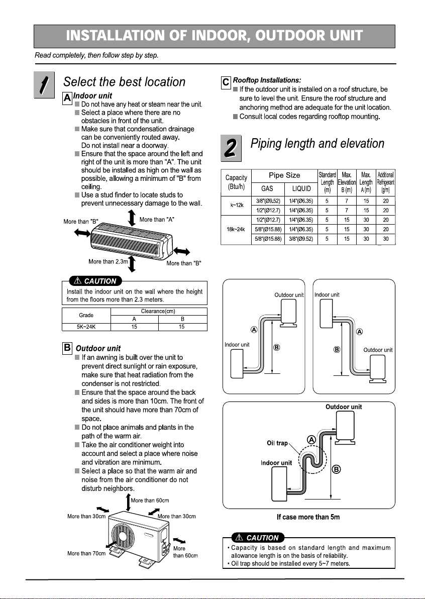
Select the best location........5
Pipe length and elevation.....5
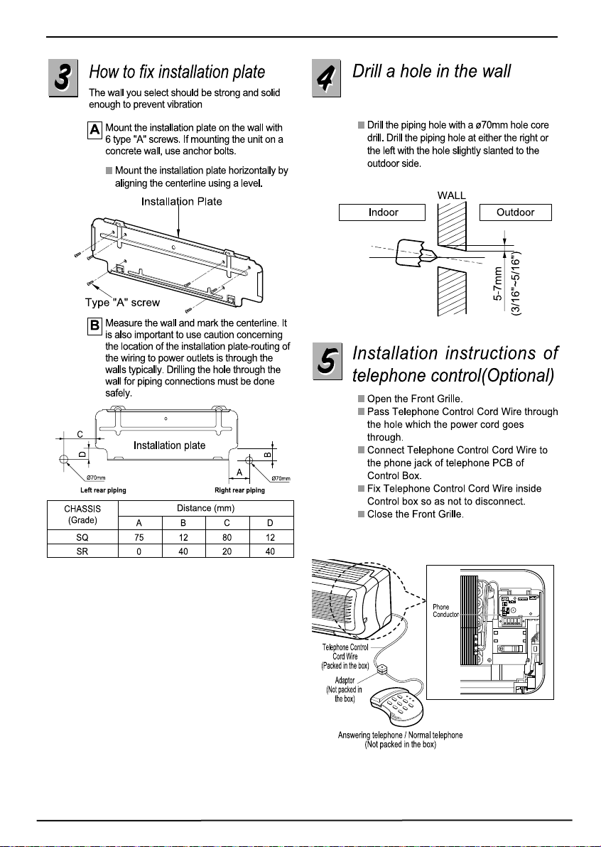
How to fix installation plate...6
Drill a hole in the wall............6
Installation instructions of
telephone control(optional)...6
7
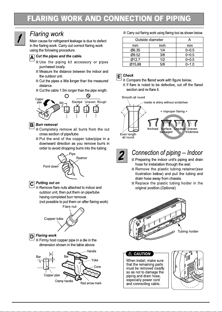
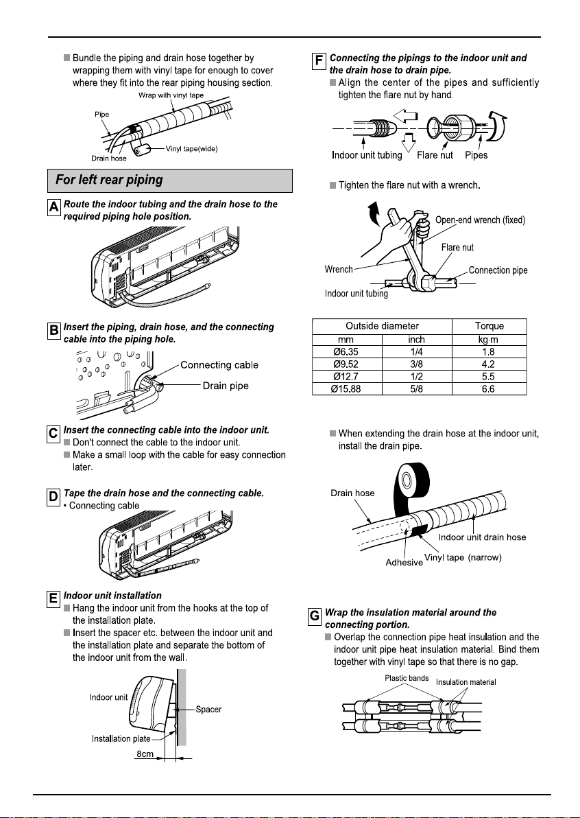
Flaring work..........................7
Connection of piping
- Indoor.................................7
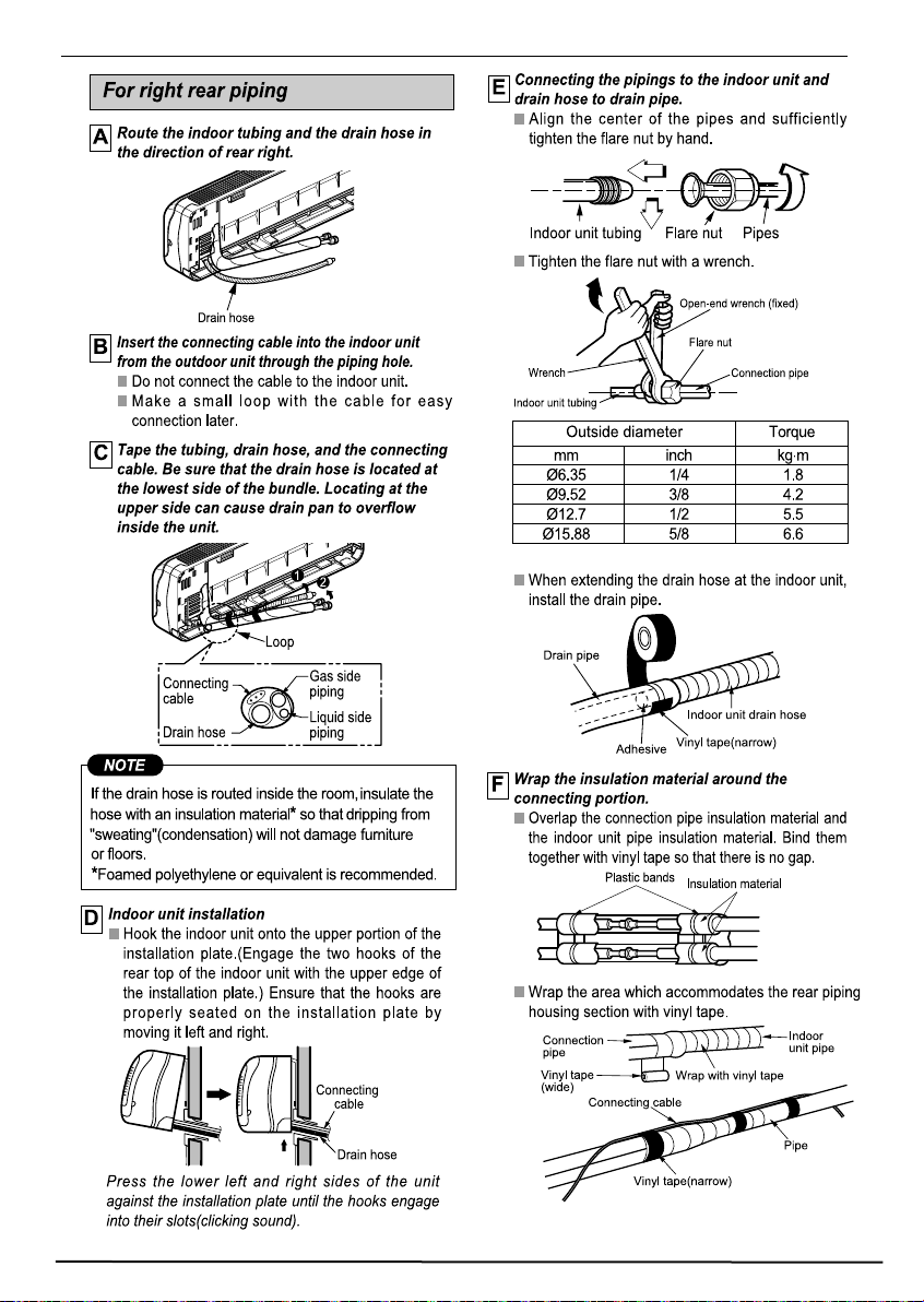
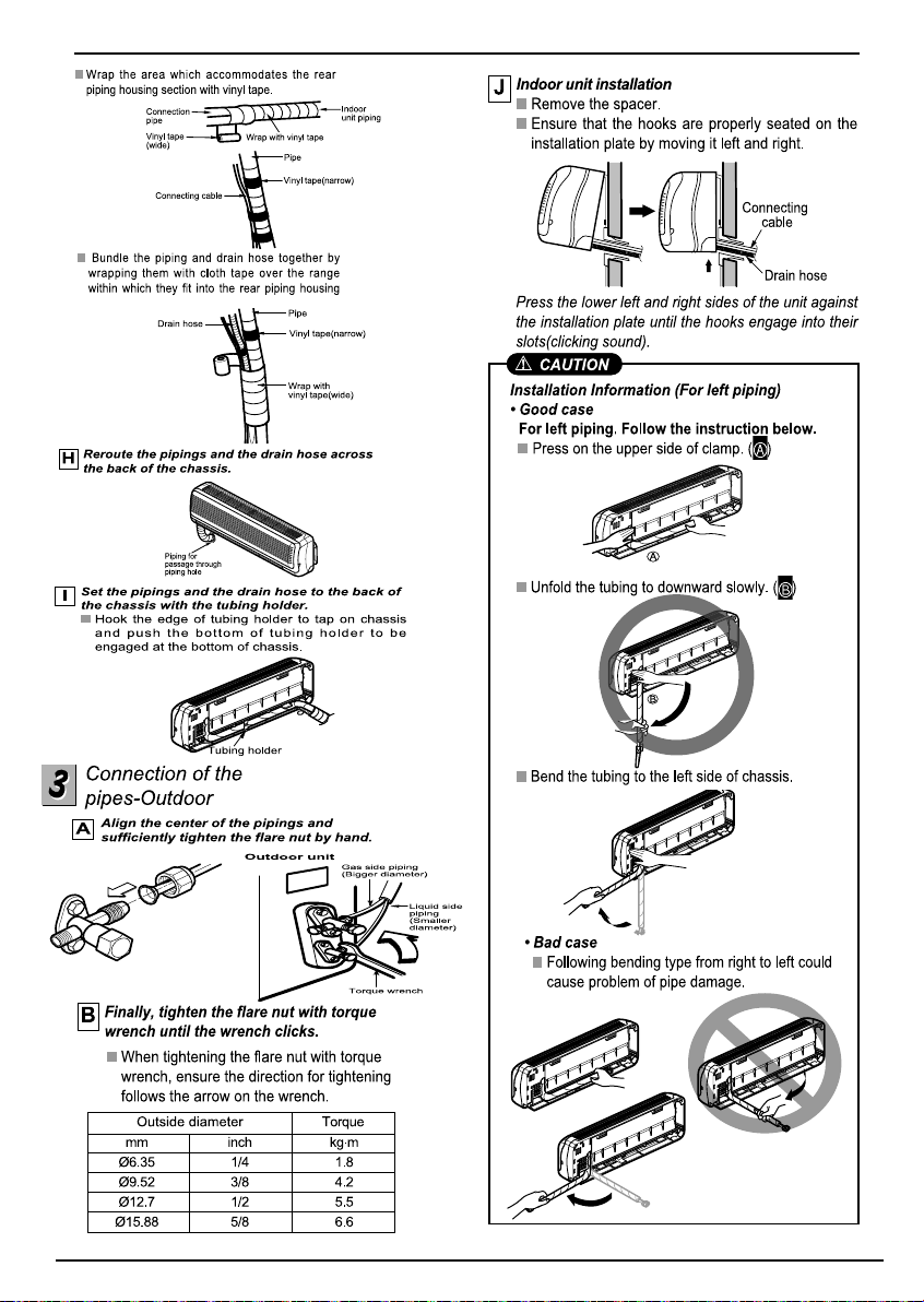
Connection of the pipes
- Outdoor............................10
11
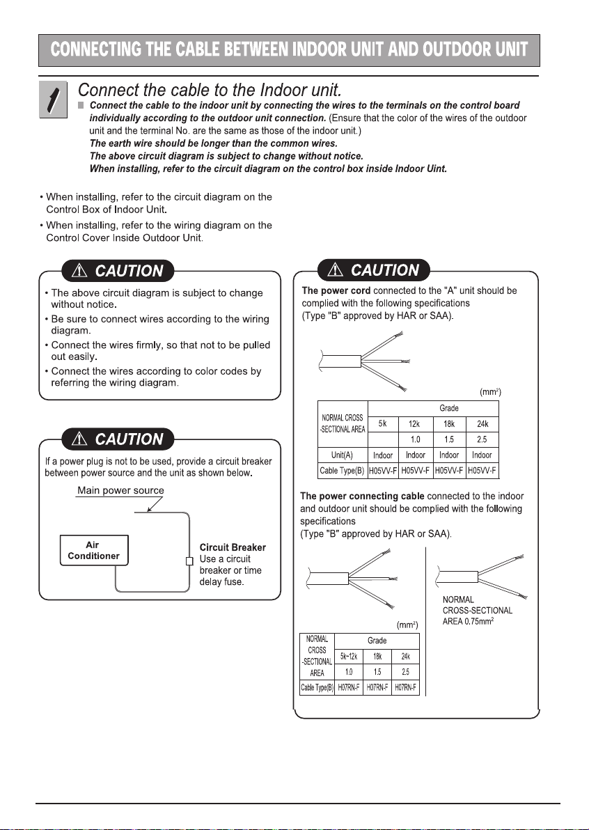
Connect the cable to the
Indoor unit...........................11
Connect the cable to the
Outdoor unit........................12
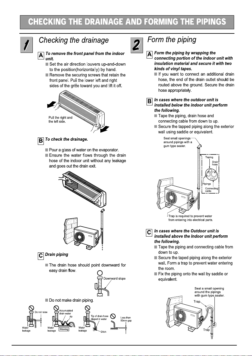
Checking the drainage and
Forming the pipings.............13
Checking the drainage........13
Form the piping...................13
14
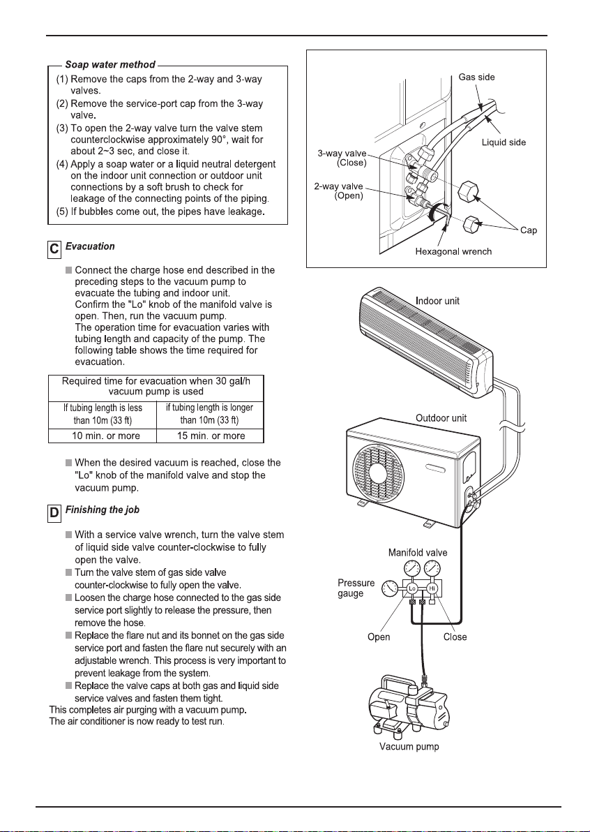
Air purging..........................14
Air purging with vacuum
pump...................................14
5
Installation guide at the
seaside
2 Installation Manual
16
17
Page 3
Installation Manual 3
Page 4
4 Installation Manual
Page 5
5
Installation Manual 5
Page 6
6 Installation Manual
Page 7
Installation Manual 7
Page 8
8 Installation Manual
Page 9
Installation Manual 9
Page 10
10 Installation Manual
Page 11
0.75-1.0
Installation Manual 11
Page 12

Type 2
Type 1
More than
5 mm
Remark :
For Cooling model .
cable
5
depending on the model.
Type 1 : Install the ground wire
on the control board.The screw
holding to the hole for ground wire
and the wire 3 lines connect to
control board as picture.
: Install the ground wire
Type 2
on the steel panel and that the
hole for ground wire no screw.
from
12 Installation Manual
Page 13
Installation Manual 13
Page 14

14 Installation Manual
Page 15
Installation Manual 15
Page 16
16 Installation manual
Page 17
INSTALLATION GUIDE AT THE SEASIDE
1.
Air conditioners should not be installed in areas where corrosive gases, such as acid or alkaline gas, are produced.
2. Do not install the product where it could be exposed to sea wind (salty wind) directly. It can result corrosion
3.
If outdoor unit is installed close to the seaside, it should avoid direct exposure to the sea wind. Otherwise it
needs additional anticorrosion treatment on the heat exchanger.
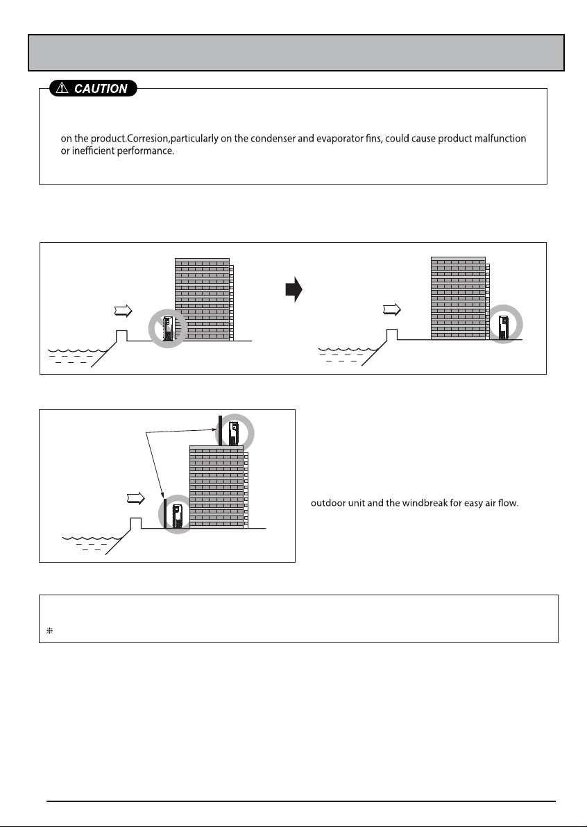
Selecting the location(Outdoor Unit)
1) If the outdoor unit is to be installed close to the seaside, then direct exposure to the sea wind should
be avoided.Install the outdoor unit on the opposite side of the sea wind direction.
Sea wind
2) In case of installing the outdoor unit on the sea side, setup a windbreak to prevent sea wind.
Windbreak
Sea wind
3) Select a well-drained place.
1.
If you can’t meet above guide line in the seaside installation, please contact LG Electronics for the additional anticorrosion treatment.
2. Periodic ( more than once/year ) cleaning of the dust or salt particles stuck on the heat exchanger by using water
Do not use seawater when you clean up the heat exchanger.
• It should be strong enough like concrete to prevent the
sea wind from the sea.
• The height and width should be more than 150%
of the outdoor unit.
• Keep more than 70 cm of space between
Sea wind
17 Installation manual
Page 18

Page 19

Page 20

Memo
Page 21

Memo
Page 22

Date : 05.2014
Rev : 01
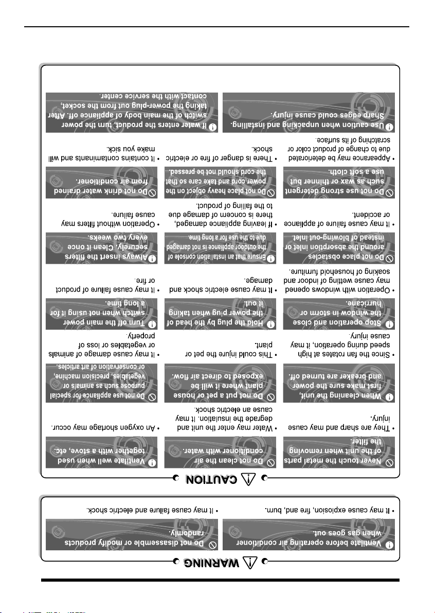
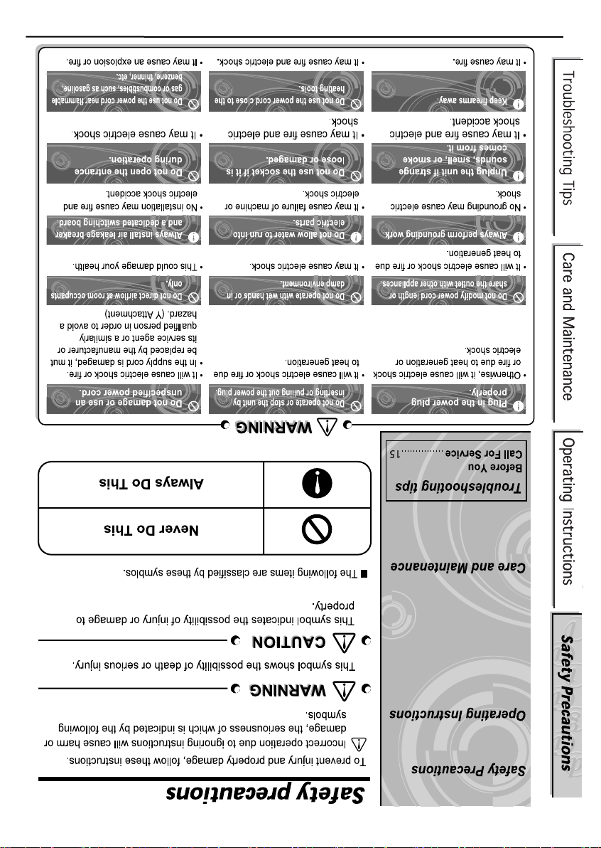
Owner ‘ s Manual 15
excess water.
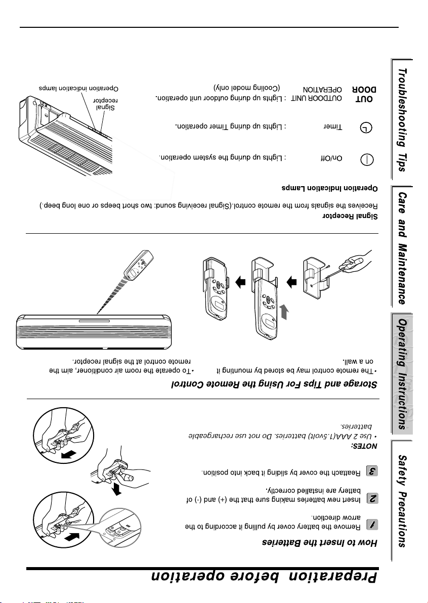
The indoor side is not water resistant and should not be exposed to
WATER RESISTANT : The outdoor side of this appliance is WATER RESISTANT.
NOTE
6,7
12
9
Before you call for service
Page 23
14 Owner ‘ s Manual
Page 24

Owner ‘s Manual 13
operating efficiency of the system and cause higher operating costs.
Dirty or clogged coils will reduce the
NOTE
cleaned.
If clogged with dirt or soot, the heat exchanger and panel vents may be professionally steam
The heat exchanger coils and panel vents of the outdoor unit should be checked regularly.
Page 25

12 Owner ‘s Manual
Page 26

Date : 05.2014
Rev : 01
Owner ‘ s Manual 11
If you want to stop the operation, re-press the button.
"beep".
If you want to use this operation, Press and hold the ON/OFF button for 3~5 seconds, then the buzzer sound 1
During test operation, if remote controller signal is received, the unit operates as remote controller sets.
temperature and resets in 18 minutes.
During the TEST OPERATION, the unit operates in cooling mode at high speed fan, regardless of room
Test operation
Page 27
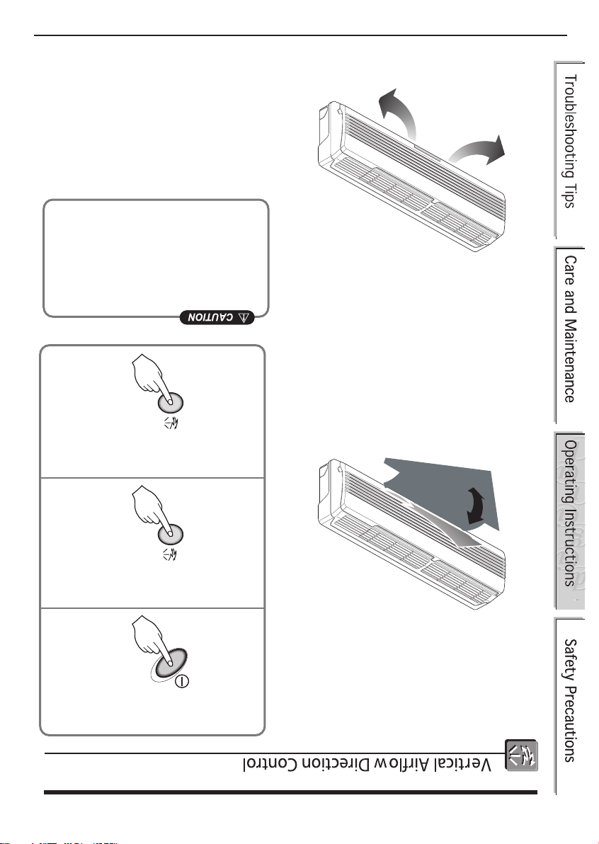
the air outlet vent of room air conditioner.
the vertical airflow direction louver will close
• When air conditioner operation is stopped,
cause operation errors.
vertical airflow direction louver by hand could
the airflow direction. Manually moving the
• Always use the remote controller to adjust
10 Owner ’ s Manual
hand.
moving the horizontal airflow direction louver by
• Adjust the horizontal airflow direction by manually
Horizontal Airflow Direction Control
at the desired airflow direction.
3
Control Button to set the vertical louver
Press again the Airflow Direction
and down automatically.
2
Button and the vertical louvers swing up
Press the Airflow Direction Control
1
(Confirm the unit on operation.)
Press the Start/Stop Button.
bath.
want to cool yourself directly, such as after taking a
using the remote controller. This is effective when you
The airflow direction can be adjusted as desired by
Airflow Direction Control
Additional features
Page 28
Owner ‘ s Manual 9
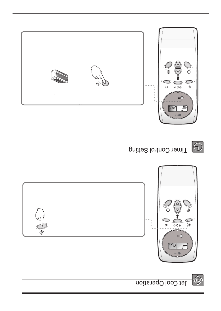
pressing the OFF Time button from 1 hour to 7 hours.
3. The Timer is programmed by 1 hour each
2. Check the OFF Time LED of the room air conditioner.
1. Press the OFF Time Button.
Beep Beep
Press the OFF Time Button.
OFF
TIME 7 hr.
TEMP.
mode.
again and the unit will operate at high fan speed on cooling
fan speed button or the room temper ature setting button
Jet Cool mode, press the Jet Cool button, the
To cancel the
on cooling mode for 30 minutes.
will operate at super high fan speed
the speed cooling mode and the unit
Press the Jet Cool button to operate
TEMP.
Page 29

fan speed mode is shifted.
Each time the button is pressed, the
steps-low, medium, high and CHAOS.
You can select the fan speed in four
TIME
hr.
OFF
of the remote controller still closed.
Set the fan speed again with the door
Set the fan speed.
8 Owner ‘ s Manual
• The indoor fan may be stopped not so as to be the room overcooling.
Control.
impossible because of already being set to the best speed for Dry Operatrion by Micom
• The indoor fan speed is automatically set to the low, so the shift of the indoor fan speed is
pe
TEMP.
eB,peeB
TIME
hr.
Dehumidification
Healthy
OFF
TEMP.
Cooling
TIME
hr.
OFF
( Heat pump model only)
Heating
TIME
hr.
OFF
shifted in the arrow direction.
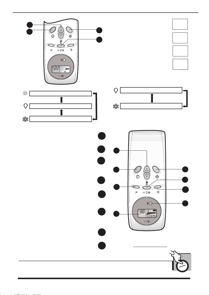
Each time the button is pressed, the operation mode is
Press the operation Mode Selection Button.
Select Healthy Dehumidification Operation.
TEMP.
Page 30

Owner ‘ s Manual 7
fan speed mode is shifted.
Each time the button is pressed, the
steps-low, medium, high and CHAOS.
You can select the fan speed in four
TIME
hr.
OFF
TEMP.
of the remote controller still closed.
Set the fan speed again with the door
TIME
hr.
OFF
TEMP.
6
( Heat pump model only)
Heating
TIME
hr.
OFF
TEMP.
Dehumidification
Healthy
hr.
TIME
OFF
Cooling
TIME
hr.
OFF
TEMP.
TEMP.
Beep Beep
Heating Operation (Heating pump only)
Page 31

6 Owner ‘ s Manual
fan speed mode is shifted.
Each time the button is pressed, the
steps-low, medium, high and CHAOS.
You can select the fan speed in four
TIME
hr.
OFF
TEMP.
of the remote controller still closed.
Set the fan speed again with the door
hr.
TIME
OFF
TEMP.
( Heat pump model only)
Heating
TIME
hr.
OFF
TEMP.
Dehumidification
Healthy
hr.
TIME
OFF
TEMP.
hr.
Cooling
TIME
OFF
TEMP.
Beep Beep
How to use the Operation mode Selection button
Page 32
Owner ‘s Manual 5
Selection Button
4
3
1
TEMP.
4
2
th
Indoor Fan Speed
Setting Button
rd
st
nd
3
2
1
Room Temperature
Button
Operation Mode Selection
Start/Stop Button
(2) OPERATION PROCEDURE
(
speed cooling
( Heat pump Model )
Heating Operation
Cooling Mode
Healthy Dehumidification Operation
operates super high fan speed in cooling mode.)
Used to start or stop the speed
8
JET COOL OPERATION BUTTON
BUTTON
7
INDOOR FAN SPEED SELECTION
BUTTONS
ROOM TEMPERATURE SETTING
pressed again.
pressed, and stops when the button is
Operation starts when this button is
START/STOP BUTTON
Used to set the time of stopping operation.
OFF TIMER BUTTON
Used to select the operation mode.
BUTTON
OPERATION MODE SELECTION
set the desired up/down airflow direction.
Used to stop or start louver movement and
BUTTON
AIRFLOW DIRECTION START/STOP
Displays the operation conditions.
OPERATION DISPLAY
6
6
5
5
2
4
3
1
hr.
TIME
TEMP.
2
1
(Cooling Model)
Cooling Mode
OFF
Signal transmitter
Healthy Dehumidification Operation
(1) OPERATION MODE
7
8
3
8
4
conditioner.
Transmits the signals to the room air
Features of the Remote Control
About the remote control on the system
Page 33
4 Owner ‘ s Manual
Page 34
Owner ‘s Manual 3
Page 35
Date : 05.2014
Rev : 01
2 Owner ‘ s Manual
Care and Maintenance.........12
Additional features................10
Selecttion button.....................6
How to use the Operation mode
the system..............................5
About the remote control on
Preparation before operation..4
Warning and caution..............2
Page 36

Date : 05.2014
Rev : 01
 Loading...