

Page 1

MODEL: HLT45W (HLT45W, SHT35-D)SERVICE MANUAL
Internal Use Only
Website http://biz.lgservice.com
DVD SOUND BAR
SERVICE MANUAL
MODEL: HLT45W
P/NO : AFN75253907 MARCH, 2011
CAUTION
BEFORE SERVICING THE UNIT, READ THE “SAFETY PRECAUTIONS”
IN THIS MANUAL.
(HLT45W, SHT35-D)
Page 2

CONTENTS
SECTION 1 ........ GENERAL
SECTION 2 ........ ELECTRICAL
SECTION 3 ........ CABINET & MAIN CHASSIS
SECTION 4 ........ REPLACEMENT PARTS LIST
1-1
Page 3

SECTION 1
GENERAL
CONTENTS
SERVICING PRECAUTIONS .......................................................................................................................... 1-3
ESD PRECAUTIONS ....................................................................................................................................... 1-5
SERVICE INFORMATION FOR EEPROM .................................................................................................... 1-6
HOW TO UPDATE AUDIO MICOM & DVD PROGRAMS ........................................................................... 1-7
FIRMWARE UPDATE FOR WIRELESS DEVICE ......................................................................................... 1-8
SPECIFICATIONS ............................................................................................................................................ 1-9
1-2
Page 4
SERVICING PRECAUTIONS
NOTES REGARDING HANDLING OF THE PICK-UP
1. Notes for transport and storage
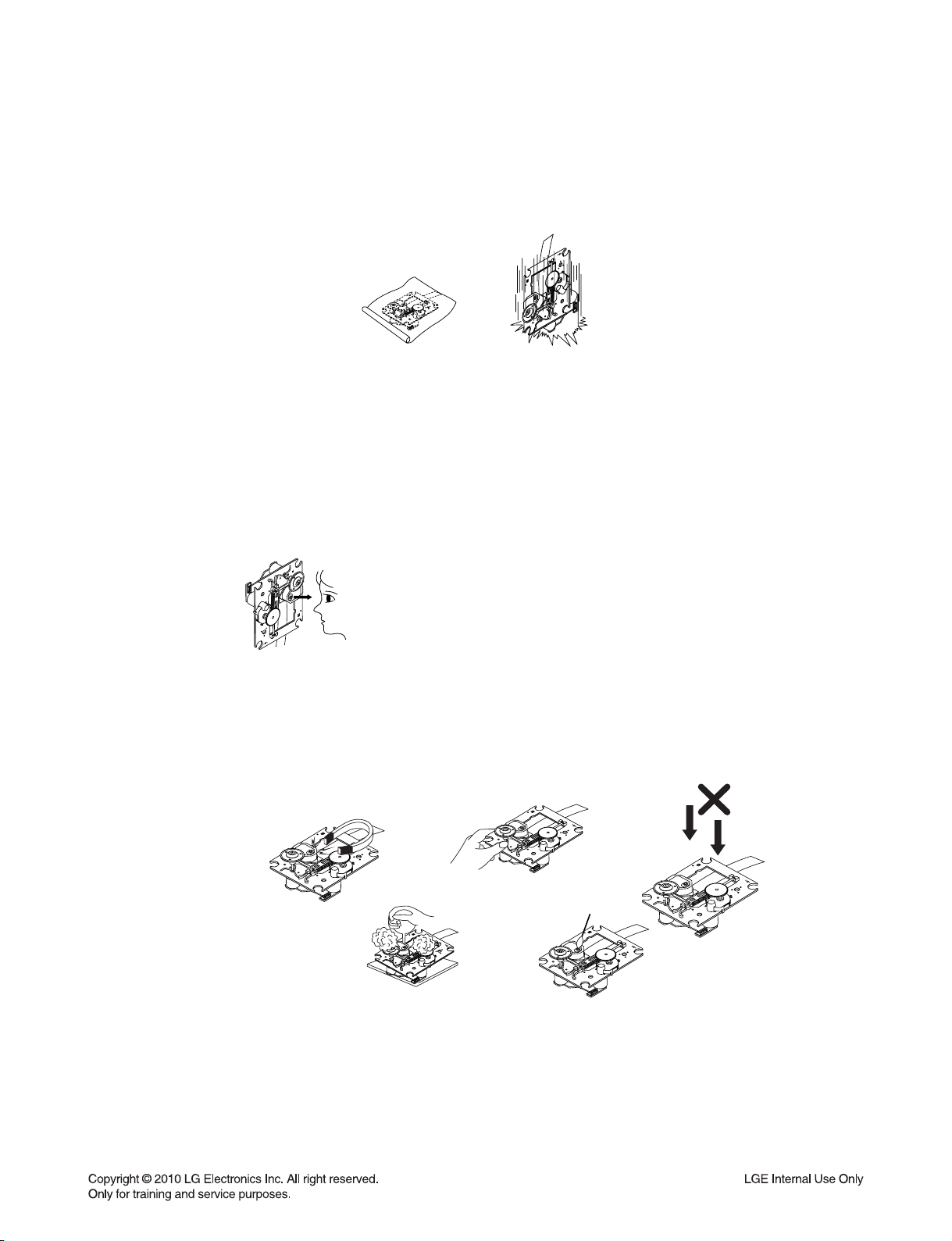
1) The pick-up should always be left in its conductive bag until immediately prior to use.
2) The pick-up should never be subjected to external pressure or impact.
Storage in conductive bag
Drop impact
2. Repair notes
1) The pick-up incorporates a strong magnet, and so should never be brought close to magnetic materials.
2) The pick-up should always be handled correctly and carefully, taking care to avoid external pressure and
impact. If it is subjected to strong pressure or impact, the result may be an operational malfunction and/or
damage to the printed-circuit board.
3) Each and every pick-up is already individually adjusted to a high degree of precision, and for that reason
the adjustment point and installation screws should absolutely never be touched.
4) Laser beams may damage the eyes!
Absolutely never permit laser beams to enter the eyes!
Also NEVER switch ON the power to the laser output part (lens, etc.) of the pick-up if it is damaged.
NEVER look directly at the laser beam, and don’t allow
contact with fingers or other exposed skin.
5) Cleaning the lens surface
If there is dust on the lens surface, the dust should be cleaned away by using an air bush (such as used
for camera lens). The lens is held by a delicate spring. When cleaning the lens surface, therefore, a cotton swab should be used, taking care not to distort lens.
Pressure
Magnet
How to hold the pick-up
Cotton swab
Conductive Sheet
6) Never attempt to disassemble the pick-up.
Spring has excess pressure. If the lens is extremely dirty, apply isopropyl alcohol to the cotton swab.
(Do not use any other liquid cleaners, because they will damage the lens.) Take care not to use too much
of this alcohol on the swab, and do not allow the alcohol to get inside the pick-up.
1-3
Pressure
Page 5

NOTES REGARDING COMPACT DISC PLAYER REPAIRS
1. Preparations
1) Compact disc players incorporate a great many ICs as well as the pick-up (laser diode). These components
are sensitive to, and easily affected by, static electricity. If such static electricity is high voltage, components
can be damaged, and for that reason components should be handled with care.
2) The pick-up is composed of many optical components and other high-precision components. Care must be
taken, therefore, to avoid repair or storage where the temperature or humidity is high, where strong magnetism is present, or where there is excessive dust.
2. Notes for repair
1) Before replacing a component part, first disconnect the power supply lead wire from the unit
2) All equipment, measuring instruments and tools must be grounded.
3) The workbench should be covered with a conductive sheet and grounded.
When removing the laser pick-up from its conductive bag, do not place the pick-up on the bag. (This is
because there is the possibility of damage by static electricity.)
4) To prevent AC leakage, the metal part of the soldering iron should be grounded.
5) Workers should be grounded by an armband (1M Ω)
6) Care should be taken not to permit the laser pick-up to come in contact with clothing, in order to prevent
static electricity changes in the clothing to escape from the armband.
7) The laser beam from the pick-up should NEVER be directly facing the eyes or bare skin.
Armband
Resistor
(1 M Ω)
Resistor
(1 M Ω)
Conductive
Sheet
1-4
Page 6
ESD PRECAUTIONS
Electrostatically Sensitive Devices (ESD)
Some semiconductor (solid state) devices can be damaged easily by static electricity. Such components
commonly are called Electrostatically Sensitive Devices (ESD). Examples of typical ESD devices are integrated
circuits and some field-effect transistors and semiconductor chip components. The following techniques should
be used to help reduce the incidence of component damage caused by static electricity.
1. Immediately before handling any semiconductor component or semiconductor-equipped assembly, drain off
any electrostatic charge on your body by touching a known earth ground. Alternatively, obtain and wear a
commercially available discharging wrist strap device, which should be removed for potential shock reasons
prior to applying power to the unit under test.
2. After removing an electrical assembly equipped with ESD devices, place the assembly on a conductive surface
such as aluminum foil, to prevent electrostatic charge buildup or exposure of the assembly.
3. Use only a grounded-tip soldering iron to solder or unsolder ESD devices.
4. Use only an anti-static solder removal device. Some solder removal devices not classified as "anti-static" can
generate electrical charges sufficient to damage ESD devices.
5. Do not use freon-propelled chemicals. These can generate electrical charges sufficient to damage ESD
devices.
6. Do not remove a replacement ESD device from its protective package until immediately before you are
ready to install it. (Most replacement ESD devices are packaged with leads electrically shorted together by
conductive foam, aluminum foil or comparable conductive materials).
7. Immediately before removing the protective material from the leads of a replacement ESD device, touch the
protective material to the chassis or circuit assembly into which the device will by installed.
CAUTION : BE SURE NO POWER IS APPLIED TO THE CHASSIS OR CIRCUIT, AND OBSERVE ALL OTHER
SAFETY PRECAUTIONS.
8. Minimize bodily motions when handing unpackaged replacement ESD devices. (Otherwise harmless motion
such as the brushing together of your clothes fabric or the lifting of your foot from a carpeted floor can generate
static electricity sufficient to damage an ESD device).
CAUTION. GRAPHIC SYMBOLS
THE LIGHTNING FLASH WITH APROWHEAD SYMBOL. WITHIN AN EQUILATERAL TRIANGLE, IS
INTENDED TO ALERT THE SERVICE PERSONNEL TO THE PRESENCE OF UNINSULATED
“DANGEROUS VOLTAGE” THAT MAY BE OF SUFFICIENT MAGNITUDE TO CONSTITUTE A RISK OF
ELECTRIC SHOCK.
THE EXCLAMATION POINT WITHIN AN EQUILATERAL TRIANGLE IS INTENDED TO ALERT THE
SERVICE PERSONNEL TO THE PRESENCE OF IMPORTANT SAFETY INFORMATION IN SERVICE
LITERATURE.
1-5
Page 7
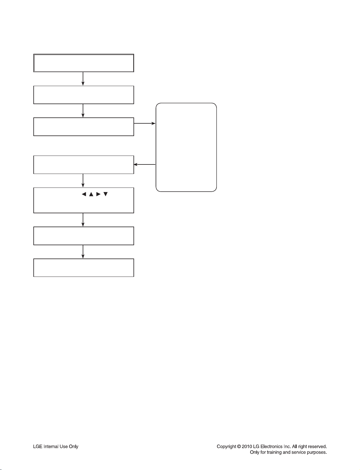
SERVICE INFORMATION FOR EEPROM
POWER ON
DVD LOGO Status (NO Disk status)
Remote control
Pause key→1→4→7→2 in order.
Press number 0~9, Press character
A~F (1~6 for a while)
Use arrow key ( ) to
move to appropriate position and
make changes
Press pause key once
DETECT NEW EEPROM
(OPTION EDIT SCREEN)
NAME
OPT 1
OPT 2
OPT 3
OPT 4
OPT 5
OPT 6
OPT 7
OPT 8
OPT 9
OPT A
HEX
F8
00
C1
D4
00
10
80
10
50
10
Change will be applied when power
OFF→ON.
1-6
Page 8

HOW TO UPDATE AUDIO MICOM & DVD PROGRAMS
1. How to update AUDIO MICOM program.
[Update using CD]
1. Change the filename to download as “HLT55_(Version).HEX”. Only upper cases are permitted.
ex) HLT55 : “HLT55_0709081.HEX”
2. Copy the file to the root folder of a CD and burn it.
3. Insert the CD to the SET, and move to the DVD function.
Then the upgrade process will be started with the upgrade information.
4. If the upgrade process is complete, the set will be rebooted with “Complete” message.
[Update using USB]
1. Change the filename to download as “HLT55_(Version).HEX”. Only upper cases are permitted.
ex) HLT55 : “HLT55_0709081.HEX”
2. Copy the file to the root folder of USB storage.
3. After Home-menu is displayed on Screen of SET, Put the USB into the SET.
Then the upgrade process will be started with the upgrade information.
4. If the upgrade process is complete, the set will be rebooted with “Complete” message.
2. How to update DVD program.
[Update using CD]
1. Copy DVD program(ex: LG_HLT55LD1_Version.Rom) to Root folder of CD, and burn it.
ex) P:LG_HLT55LD1_0911180.Rom
2. Insert the CD to the SET, then after a while the CD tray will be opened with upgrade information on
the screen.
3. Remove the CD, and press “PLAY” key in remote controller.
4. Remove and reconnect the power cable when it changes to logo screen from upgrade information.
Then the upgrade process is completed.
[Update using USB]
1. Copy DVD program(ex: LG_HLT55LD1_Version.Rom) to Root folder of the formatted USB and burn it.
ex) P:\LG_HLT55LD1_0911180.Rom
2. After Home-menu is displayed on Screen of SET, Put the USB into the SET.
Then the upgrade process will be started with the upgrade information.
3. Remove the USB, press "PLAY" key of the remote controller.
4. Remove and reconnect the power cable when it changes to logo screen from upgrade information.
Then the upgrade process is completed.
1-7
Page 9

FIRMWARE UPDATE FOR WIRELESS DEVICE
1. WIRELESS MODULE UPDATE METHOD
Update must be performed without interference.
1) Select “1” on test band.
- You must select a band without interference.
2) USB update
- During the software update procedure, do not turn off the unit.
2-1) Copy the update fi le to the USB device after rename as “WIRELESS.BIN”.
2-2) Insert a USB device and perform the update.
- It is indicated “SEND xx” during transmission (xx is progress rate %.).
- LED is turned off during RX writing.
※
※ At this time, turn off RX/TX then update will fail and the previous version of program will work.
- If RX update is fi nished, LED light is on.
- If TX update is fi nished, it is power off automatically.
2-3) If the update is fi nished, TX is power off. RX is turned on after LED light is off.
3) Remove the power cord. After 5 seconds, reconnect the cord and turn on TX.
4) Factory
4-1) Press set “STOP” + remote control “6” during 3 seconds to perform TX FACTORY.
- “WL RESET” appears on FLD.
4-2) Press PAIRING button on RX during 5 seconds.
- LED blinks blue and red alternately to 0.5 second intervals.
In case of connection is unstable; In case of update is no response more than 20 seconds; Update fail.
Condition:
1) Wireless module update must be performed without interference.
2) You must update after switching TEST BAND.
3) After wireless module update, you must perform TX/RX FACTORY.
2. WIRELESS MICOM UPDATE METHOD
Update must be performed without interference.
1) Select “1” on test band.
- You must select a band without interference.
2) USB update
- During the software update procedure, do not turn off the unit.
2-1) Copy the update fi le to the USB device after rename as “WIRELESS_MICOM.HEX”.
2-2) Insert a USB device and perform the update.
- It is indicated “SEND xx” during transmission (xx is progress rate %.).
- “FINALIZE” indication is blinked to FLD of main set during RX MICOM writing.
※
※ At this time, turn off RX/TX then Micom update will fail and the previous version of program will work.
2-3) If the update is fi nished, RX LED is turned off and on. Main set is power off automatically.
3) Remove the power cord. After 5 seconds, reconnect the cord and turn on TX.
Condition:
1) Wireless module update must be performed without interference.
2) You must update after switching TEST BAND.
In case of connection is unstable; In case of update is no response more than 20 seconds; Update fail.
1-8
Page 10

SPECIFICATIONS
• GENERAL
Power requirements: Refer to main label.
Power consumption: Refer to main label.
Dimensions (W x H x D): 800 x 160 x 80 mm without foot
Net Weight (Approx.): 4.6 kg
Operating temperature: 41 °F to 95 °F (5 °C to 35 °C)
Operating humidity: 5 % to 90 %
Bus Power supply (USB): DC 5V 500 mA
• INPUTS / OUTPUTS
VIDEO OUT: 1.0 V (p-p), 75 Ω, sync negative, RCA jack x 1
HDMI OUT (video/audio): 19 pin (HDMI standard, Type A), HDMI version : 1.2A
ANALOG AUDIO IN: 2.0 Vrms (1 kHz, 0 dB), 600 Ω, RCA jack (L, R) x 1
DIGITAL IN (OPTICAL 1): 3 V (p-p), Optical jack x 1
PORT. IN: 0.5 Vrms (3.5 mm stereo jack)
• TUNER
FM Tuning Range: 87.5 to 108.0 MHz or 87.50 to 108.00 MHz
• AMPLIFIER
Stereo mode: 60 W + 60 W (4 Ω at 1 kHz)
Surround mode:
Front 60 W + 60 W (4 Ω at 1 kHz)
Center 30 W + 30 W (8 Ω at 1 kHz)
Subwoofer 150 W (3 Ω at 60 Hz))
• WIRELESS SUBWOOFER
Power requirements: Refer to main label on the Subwoofer.
Power consumption: Refer to main label on the Subwoofer.
Reception Output: 5.8 GHz
Subwoofer
Type: 1 Way 1 speaker
Impedance Rated: 3 Ω
Input Power: 150 W
Max. Input power: 300 W
Net Dimensions (W x H x D): 196 x 390 x 356 mm
Net Weight: 7.1 kg
1-9
Page 11

MEMO
1-10
Page 12

SECTION 2
ELECTRICAL
CONTENTS
DIGITAL DISPLAY & MEDIA TRAINING MASTER ..................................................................................... 2-2
1. DISTORTED PICTURE ........................................................................................................................... 2-2
2. NO PICTURE .......................................................................................................................................... 2-7
3. PICTURE COLOR ................................................................................................................................. 2-12
4. NOISE/AUDIO PROBLEMS .................................................................................................................. 2-14
5. MISCELLANEOUS ................................................................................................................................ 2-17
COMPONENT REPAIR GUIDE .................................................................................................................... 2-26
1. DVD SOUNDBAR COMPONENT REPAIR GUIDE .............................................................................. 2-26
2. WIRELESS SUBWOOFER COMPONENT REPAIR GUIDE................................................................ 2-33
ELECTRICAL TROUBLESHOOTING GUIDE ............................................................................................. 2-35
1. DVD SOUNDBAR TROUBLESHOOTING ............................................................................................ 2-35
DETAILS AND WAVEFORMS ON SYSTEM TEST AND DEBUGGING .................................................. 2-48
1. 1. SYSTEM 27 MHZ CLOCK,RESET,FLASH R/W SIGNAL ................................................................ 2-48
2. SDRAM CLOCK .................................................................................................................................... 2-49
3. VIDEO PART-1 (100% FULL COLOR-BAR) ........................................................................................ 2-50
4. VIDEO PART-2 (100% FULL COLOR-BAR) ........................................................................................ 2-50
5. HDMI PART .......................................................................................................................................... 2-51
6. SERVO OPEN/CLOSE SIGNAL ........................................................................................................... 2-52
WIRING DIAGRAMS ...................................................................................................................................... 2-61
1. DVD SOUNDBAR WIRING DIAGRAM ................................................................................................. 2-61
BLOCK DIAGRAMS ...................................................................................................................................... 2-63
1. DVD SOUNDBAR BLOCK DIAGRAMS ................................................................................................ 2-63
2. WIRELESS SUBWOOFER BLOCK DIAGRAM .................................................................................... 2-67
CIRCUIT DIAGRAMS .................................................................................................................................... 2-69
1. DVD SOUNDBAR CIRCUIT DIAGRAMS ............................................................................................. 2-69
2. WIRELESS SUBWOOFER CIRCUIT DIAGRAMS ............................................................................... 2-87
CIRCUIT VOLTAGE CHART ........................................................................................................................ 2-95
PRINTED CIRCUIT BOARD DIAGRAMS .................................................................................................... 2-99
1. DVD SOUNDBAR P. C. BOARD .......................................................................................................... 2-99
2. WIRELESS SUBWOOFER P. C. BOARD .......................................................................................... 2-109
2-1
Page 13

DIGITAL DISPLAY & MEDIA TRAINING MASTER
Objective: To provide clear and concise guidelines for customer service agents to handle calls on
box goods calls.
1. DISTORTED PICTURE
1-1. Lines on Picture
Distorted picture refers to the customer getting video, but there is a problem with the video.
Determine what cables the customer is using to connect
What cables is
the customer using to
connect the DVD?
YES
NO
the DVD to the TV and if connected properly. Refer to OM for
connections. Tighten any loose cables. Make sure the customer
is not connecting a DVD to VCR.
Copy protection can distort the picture on older DVD models.
Is the TV set
to the correct input?
YES
Do lines appear when
watching multiple discs?
YES
Do lines appear when
watching a TV program?
YES
Do lines appear
when the DVD is
connected to another TV?
NO
NO
NO
NO
Make sure the TV is on the correct input.
Turn TV off, then on to determine input.
Video when using composite, or component.
DVI when using DVI, and HDMI when using HDMI.
One disc displaying the issue is a problem with the disc.
Multiple discs displaying the problem could indicate the DVD lens
needs to be cleaned. Recommend the customer use a lens
cleaner on the DVD. A lens cleaner is available at any local
electronics retailer.
Lines appearing when watching a TV program indicates
an issue with the display. If the TV program is fine,
then connect the DVD to another input on the display to
determine if the problem is following the DVD.
Connect the DVD to another TV and play a disc.
No lines during disc play back indicates a problem with the first TV.
Please refer to the owners manual for instructions on how to
connect the DVD to a TV. If the DVD has a problem on the
second TV, then see service chart for service information.
YES
Has the customer tried
another set of cables?
NO
Have the customer try another set of cables. A bad cable can
also cause video problems. Test the cable with another device to
the TV to also determine if the TV is bad. If DVD is problem,
please see service chart for service information.
2-2
Page 14

DIGITAL DISPLAY & MEDIA TRAINING MASTER
1-2. Ghost Picture
Distorted picture refers to the customer getting video, but there is a problem with the video.
Determine what cables the customer is using to connect the DVD to
What cables is the customer
using to connect the DVD?
YES
NO
the TV and if connected properly. Refer to OM for connections.
Tighten any loose cables. Make sure the customer is not connecting a
DVD to VCR or DVD. Copy protection can distort
the picture on older VCR models.
Is the TV set to
the correct input?
YES
Do ghosting appear when
watching multiple discs?
YES
Do lines appear when
watching a TV program?
YES
Does ghosting
appear when the DVD is
connected to another TV?
NO
NO
NO
NO
Make sure the TV is on the correct input. Turn TV off,
then on to determine input. Video when using composite,
or component. DVI when using DVI, and HDMI when using HDMI.
One disc displaying the issue is a problem with the disc.
Multiple discs displaying the problem could indicate the DVD lens
needs to be cleaned. Recommend the customer use a lens cleaner
on the DVD. A lens cleaner is available at any local electronics retailer.
Ghosting appearing when watching a TV program indicates an
issue with the display. If the TV program is fine, then connect
the DVD to another input on the display to determine
if the problem is following the DVD.
Connect the DVD to another TV and play a disc.
No ghosting during disc play back indicates a problem with the first TV.
Please refer to the owners manual for instructions on how to
connect the DVD to a TV. If the DVD has a problem on the second TV,
then see service chart for service information.
YES
Has the customer tried
another set of cables?
NO
Have the customer try another set of cables. A bad cable can
also cause video problems. Test the cable with another device to
the TV to also determine if the TV is bad. If DVD is problem,
please see service chart for service information.
2-3
Page 15

DIGITAL DISPLAY & MEDIA TRAINING MASTER
1-3. Rolling Picture
Distorted picture refers to the customer getting video, but there is a problem with the video.
Determine what cables the customer is using to connect the DVD to
What cables is the customer
using to connect the DVD?
YES
NO
the TV and if connected properly. Refer to OM for connections.
Tighten any loose cables. Make sure the customer is not connecting
a DVD to VCR. Copy protection can distort
the picture on older VCR models.
Is the TV set to
the correct input?
YES
Does rolling appear when
watching multiple discs?
YES
Does rolling appear when
watching a TV program?
YES
Does rolling appear
when the DVD is connected to
another TV?
NO
NO
NO
NO
Make sure the TV is on the correct input. Turn TV off,
then on to determine input. Video when using composite,
or component. DVI when using DVI, and HDMI when using HDMI.
One disc displaying the issue is a problem with the disc.
Multiple discs displaying the problem could indicate the DVD lens
needs to be cleaned. Recommend the customer use a lens cleaner
on the DVD. A lens cleaner is available at any local electronics retailer.
Rolling appearing when watching a TV program indicates
an issue with the display. If the TV program is fine, then connect
the DVD to another input on the display to determine if the problem
is following the DVD.
Connect the DVD to another TV and play a disc. No lines during disc
playback indicates a problem with the first TV.
Please refer to the owners manual for instructions on how to connect the
DVD to a TV. If the DVD has a problem on the second TV,
then see service chart for service information.
YES
Has the customer tried
another set of cables?
NO
Have the customer try another set of cables. A bad cable can also
cause video problems. Test the cable with another device to the TV
to also determine if the TV is bad. If DVD is problem,
please see service chart for service information.
2-4
Page 16
DIGITAL DISPLAY & MEDIA TRAINING MASTER
1-4. Shaky Picture
Distorted picture refers to the customer getting video, but there is a problem with the video.
Determine what cables the customer is using to connect the DVD to
What cables is the customer
using to connect the DVD?
YES
NO
the TV and if connected properly. Refer to OM for connections.
Tighten any loose cables.
Make sure the customer is not connecting a DVD.
Copy protection can distort the picture on older VCR models.
Is the TV set to
the correct input?
YES
Does shaking appear when
watching multiple discs?
YES
Does shaking appear when
watching a TV program?
YES
Does shaking appear
when the DVD is connected to
another TV?
NO
NO
NO
NO
Make sure the TV is on the correct input. Turn TV off, then on
to determine input. Video when using composite, or component.
DVI when using DVI, and HDMI when using HDMI.
One disc displaying the issue is a problem with the disc.
Multiple discs displaying the problem could indicate the DVD lens
needs to be cleaned. Recommend the customer use a lens cleaner
on the DVD. A lens cleaner is available at any local electronics retailer.
Shaking appearing when watching a TV program indicates an issue with
the display. If the TV program is fine, then connect the DVD to another
input on the display to determine if the problem is following the DVD.
Connect the DVD to another TV and play a disc. No shaking during
disc play back indicates a problem with the first TV. Please refer to
the owners manual for instructions on how to connect the DVD to a TV.
If the DVD has a problem on the second TV,
then see service chart for service information.
YES
Has the customer tried
another set of cables?
NO
Have the customer try another set of cables. A bad cable can
also cause video problems. Test the cable with another device to
the TV to also determine if the TV is bad. If DVD is problem,
please see service chart for service information.
2-5
Page 17

DIGITAL DISPLAY & MEDIA TRAINING MASTER
1-5. Blurry Picture
Distorted picture refers to the customer getting video, but there is a problem with the video.
Determine what cables the customer is using to connect the DVD to
What cables is the customer
using to connect the DVD?
YES
NO
the TV and if connected properly. Refer to OM for connections.
Tighten any loose cables. Make sure the customer is not connecting
a DVD to VCR. Copy protection can distort
the picture on older VCR models.
Is the TV set to
the correct input?
YES
Does blurriness appear when
watching multiple discs?
YES
Does blurriness appear when
watching a TV program?
YES
Does blurriness appear
when the DVD is connected to
another TV?
NO
NO
NO
NO
Make sure the TV is on the correct input. Turn TV off,
then on to determine input. Video when using composite, or component.
DVI when using DVI, and HDMI when using HDMI.
One disc displaying the issue is a problem with the disc.
Multiple discs displaying the problem could indicate the DVD lens
needs to be cleaned. Recommend the customer use a lens cleaner on
the DVD. A lens cleaner is available at any local electronics retailer.
Blurriness appearing when watching a TV program indicates an
issue with the display. If the TV program is fine, then connect
the DVD to another input on the display to determine if the problem
is following the DVD.
Connect the DVD to another TV and play a disc. No blurriness
during disc play back indicates a problem with the first TV.
Please refer to the owners manual for instructions on how to connect
the DVD to a TV. If the DVD has a problem on the second TV,
then see service chart for service information.
YES
Has the customer tried
another set of cables?
NO
Have the customer try another set of cables.
A bad cable can also cause video problems. Test the cable with another
device to the TV to also determine if the TV is bad. If DVD is problem,
please see service chart for service information.
2-6
Page 18
DIGITAL DISPLAY & MEDIA TRAINING MASTER
2. NO PICTURE
2-1. Black Screen
The entire screen is black.
Does the DVD on-screen
menu appear?
YES
What cables is the customer
using to connect the DVD?
YES
Is the TV set to
the correct input?
YES
Is the customer able to
watch TV programming?
NO
NO
NO
NO
Make sure the customer did not select 480i resolution in the menu
of the DVD HTS if using HDMI connections. Change resolution on
upconversion DVD HTS by pushing the resolution button of the remote
controller. HDMI don’t support 480i resolution.
Determine what cables the customer is using to connect the DVD to
the TV and if connected properly. Refer to OM for connections.
Tighten any loose cables. Make sure the customer is not connecting a
DVD to VCR. Copy protection can distort
the picture on older VCR models.
Make sure the TV is on the correct input. Turn TV off,
then on to determine input. Video when using composite, or component.
DVI when using DVI, and HDMI when using HDMI.
If the customer is not able to watch television then he may have a
problem with his television, especially if the cable signal comes
through on a different input. If the customer can not get a TV program,
then he still may have a problem with the particular input on his TV.
YES
Can the customer connect
the DVD to another TV?
YES
Has the customer tried
another set of cables?
NO
NO
Have the customer connect the DVD to another TV in order to
determine if the problem is the DVD or the TV. Refer to the OM for
connections assistance. If the DVD works on the second TV,
then the customer has a problem with his TV.
Have the customer try another set of cables. A bad cable can
also cause video problems. Test the cable with another device to the TV
to also determine if the TV is bad. If DVD is problem,
please see service chart for service information.
2-7
Page 19

DIGITAL DISPLAY & MEDIA TRAINING MASTER
2-2. Blue Screen
The entire screen is a solid blue color.
Does the DVD on-screen
menu appear?
YES
What cables is the customer
using to connect the DVD?
YES
Is the TV set to
the correct input?
YES
Is the customer able to
watch TV programming?
NO
NO
NO
NO
Make sure the customer did not select 480i resolution in the menu
of the DVD HTS if using HDMI connections. Change resolution on
upconversion DVD HTS by pushing the resolution button of the remote
controller. HDMI don’t support 480i resolution.
Determine what cables the customer is using to connect the DVD
to the TV and if connected properly. Refer to OM for connections.
Tighten any loose cables. Make sure the customer is not connecting a
DVD to VCR. Copy protection can distort
the picture on older VCR models.
Make sure the TV is on the correct input.
Turn TV off, then on to determine input. Video when using composite,
or component. DVI when using DVI, and HDMI when using HDMI.
If the customer is not able to watch television then he may have a
problem with his television, especially if the cable signal comes
through on a different input. If the customer can not get a TV program,
then he still may have a problem with the particular input on his TV.
YES
Can the customer connect
the DVD to another TV?
YES
Has the customer tried
another set of cables?
NO
NO
Have the customer connect the DVD to another TV in order to
determine if the problem is the DVD or the TV. Refer to the OM for
connections assistance. If the DVD works on the second TV,
then the customer has a problem with his TV.
Have the customer try another set of cables. A bad cable can also
cause video problems. Test the cable with another device to
the TV to also determine if the TV is bad. If DVD is problem,
please see service chart for service information.
2-8
Page 20

DIGITAL DISPLAY & MEDIA TRAINING MASTER
2-3. Snowy Screen
A snowy picture is when black and white dots are all over the screen.
Does the DVD on-screen
menu appear?
YES
What cables is the customer
using to connect the DVD?
YES
Is the TV set to
the correct input?
YES
Is the customer able to
watch TV programming?
NO
NO
NO
NO
Make sure the customer did not select 480i resolution in the menu
of the DVD HTS if using HDMI connections. Change resolution on
upconversion DVD HTS by pushing the resolution button of the remote
controller. HDMI don’t support 480i resolution.
Determine what cables the customer is using to connect the DVD
to the TV and if connected properly. Refer to OM for connections.
Tighten any loose cables. Make sure the customer is not connecting a
DVD to VCR. Copy protection can distort
the picture on older VCR models.
Make sure the TV is on the correct input. Turn TV off,
then on to determine input. Video when using composite, or component.
DVI when using DVI, and HDMI when using HDMI.
If the customer is not able to watch television then he may
have a problem with his television, especially if the cable signal comes
through on a different input. If the customer can not get a TV program,
then he still may have a problem with the particular input on his TV.
YES
Can the customer connect
the DVD to another TV?
YES
Has the customer tried
another set of cables?
NO
NO
Have the customer connect the DVD to another TV in order to
determine if the problem is the DVD or the TV. Refer to the OM for
connections assistance. If the DVD works on the second TV,
then the customer has a problem with his TV.
Have the customer try another set of cables. A bad cable can
also cause video problems. Test the cable with another device to
the TV to also determine if the TV is bad. If DVD is problem,
please see service chart for service information.
2-9
Page 21
DIGITAL DISPLAY & MEDIA TRAINING MASTER
2-4. No Signal
A “no signal” message appears on the screen of the display.
Does the DVD on-screen
menu appear?
YES
What cables is the customer
using to connect the DVD?
YES
Is the TV set to the
correct input?
YES
Is the customer able to
watch TV programming?
NO
NO
NO
NO
Make sure the customer did not select 480i resolution in the
menu of the DVD HTS if using HDMI connections. Change resolution on
upconversion DVD HTS by pushing the resolution button of the remote
controller. HDMI don’t support 480i resolution.
Determine what cables the customer is using to connect the DVD
to the TV and if connected properly. Refer to OM for connections.
Tighten any loose cables. Make sure the customer is not connecting
a DVD to VCR or DVD to DVD Recorder.
Copy protection can distort the picture on older VCR models.
Make sure the TV is on the correct input. Turn TV off,
then on to determine input. Video when using composite, or component.
DVI when using DVI, and HDMI when using HDMI.
If the customer is not able to watch television then he may have a
problem with his television, especially if the cable signal comes
through on a different input. If the customer can not get a TV program,
then he still may have a problem with the particular input on his TV.
YES
Can the customer connect
the DVD to another TV?
YES
Has the customer tried
another set of cables?
NO
NO
Have the customer connect the DVD to another TV in order to
determine if the problem is the DVD or the TV. Refer to the OM for
connections assistance. If the DVD works on the second TV,
then the customer has a problem with his TV.
Have the customer try another set of cables. A bad cable
can also cause video problems. Test the cable with another device to
the TV to also determine if the TV is bad. If DVD is problem,
please see service chart for service information.
2-10
Page 22

DIGITAL DISPLAY & MEDIA TRAINING MASTER
2-5. Invalid Format or Format Not Supported
Is the customer using a
digital cable connection?
YES
Is the customer using an
analog cable connection?
YES
Is the display
HDCP compliant?
YES
Has the customer tried the
device on another display?
NO
NO
NO
NO
Customer’s using an DVI, or HDMI cable connection need to set the
resolution on the product above 480I. HDMI,
DVI connections can not process a 480I resolution.
They can only process a 480P, 720P, 1080I, or 1080P resolution.
Make sure the customer’s simultaneously connecting analog component
cable with HDMI cable. And then If Copy Protected Disc is playing back,
analog component output is no picture. Only when the analog output is
480I, you can see the picture. In case of No Copy Protected Disc,
you can see the picture regardless of the resolution.
Make sure the display is HDCP compliant when using a DVI or
HDMI connection. A lack of HDCP compliancy on the display may
cause an invalid format or format not supported message to appear.
It can also cause a copy protection OSD to appear.
Ask the customer to connect the device to another display.
If the device starts working, then the problem may be the original display.
The customer will need to troubleshoot the display. If the device
still does not work, then the problem may be the device or the cable.
YES
Has the customer tried
another cable?
NO
Ask the customer to replace the cable between the device and display.
If the problem is corrected, then the problem was with the cable.
If the problem continues, then the device is the problem.
Set up service according to in warranty or out of warranty procedures.
2-11
Page 23

DIGITAL DISPLAY & MEDIA TRAINING MASTER
3. PICTURE COLOR
3-1. No Color
The video displays no color and only shows in black and white.
What cables is the customer
using to connect the DVD?
YES
Is the TV set to the
correct input?
YES
Does color appear when
watching multiple discs?
YES
Does color appear when
watching a TV program?
NO
NO
NO
NO
Determine what cables the customer is using to connect the DVD
to the TV and if connected properly. Refer to OM for connections.
Tighten any loose cables. Make sure the customer is not connecting a
DVD to VCR. Copy protection can distort the picture on older VCR models.
Make sure the TV is on the correct input according to the
connections in use. Video when using composite, or component.
DVI when using DVI, and HDMI when using HDMI.
One disc displaying the issue is a problem with the disc.
Make sure the discs the customer is using are compatible with the
DVD by checking “playable discs” in the owners manual.
Multiple discs displaying the problem indicates a problem with
the DVD HTS.
If the cable or satellite programming is connected through
another input and the customer does not get color, the customer has a
problem with his television. If a TV program does have the color,
the problem may be the DVD HTS, the cables being used,
or the TV itself.
YES
Does color appear
when the DVD is
connected to another TV?
YES
Has the customer tried
another set of cables?
NO
NO
Connect the DVD to another TV and play a disc. Good color during
disc play back indicates a problem with the first TV. Please refer to the
owners manual for instructions on how to connect the DVD to a TV.
If the DVD has a problem on the second TV, then see service chart for
service information.
Have the customer try another set of cables. A bad cable can
also cause video problems. Test the cable with another device to
the TV to also determine if the TV is bad. If the DVD is the problem,
please see service chart for service information.
2-12
Page 24

DIGITAL DISPLAY & MEDIA TRAINING MASTER
3-2. Poor Color
The color is poor. Examples would be washed out colors, colors bleeding into one another, or a solid tint to
a screen.
What cables is the customer
using to connect the DVD?
YES
Is the TV set to the
correct input?
YES
Is color fine when watching
multiple discs?
YES
Is color fine when watching
a TV program?
NO
NO
NO
NO
Determine what cables the customer is using to connect the DVD to
the TV and if connected properly. Refer to OM for connections.
Tighten any loose cables. Make sure the customer is not connecting a
DVD to VCR. Copy protection can distort the picture on older VCR models.
Make sure the TV is on the correct input according to the
connections in use. Video when using composite, or component.
DVI when using DVI, and HDMI when using HDMI.
One disc displaying the issue is a problem with the disc.
Make sure the discs the customer is using are compatible with the DVD
by checking “playable discs” in the owners manual. Multiple discs
displaying the problem indicates a problem with the DVD HTS.
If the cable or satellite programming is connected through another
input and the customer does not get color, the customer has a problem
with his television. If a TV program does have the color, the problem
may be the DVD HTS, the cables being used, or the TV itself.
YES
Is color fine when the DVD is
connected to another TV?
YES
Has the customer tried
another set of cables?
NO
NO
Connect the DVD to another TV and play a disc. Good color during
disc play back indicates a problem with the first TV. Please refer to the
owners manual for instructions on how to connect the DVD to a TV.
If the DVD has a problem on the second TV, then see service
chart for service information.
Have the customer try another set of cables. A bad cable
can also cause video problems. Test the cable with another device to
the TV to also determine if the TV is bad. If the DVD is the problem,
please see service chart for service information.
2-13
Page 25

DIGITAL DISPLAY & MEDIA TRAINING MASTER
4. NOISE/AUDIO PROBLEMS
4-1. No Audio
The customer is not able to get audio.
What cables is the customer
using to connect the DVD?
YES
NO
Determine what cables the customer is using to connect the DVD
to the TV and if connected properly. Refer to OM for connections.
Tighten any loose cables. Make sure the customer has audio cables
connected if using an HDMI to DVI adapter or video-only cables
(DVI, component, etc).
Is the customer
able to see video?
YES
Does issue occur on
more than one disc?
YES
Problem occur when
watching TV program?
YES
Does the problem occur
when DVD is connected to
another TV?
NO
NO
NO
NO
Make sure the customer has not routed video
and audio to separate inputs.
Problem occurring on one disc indicates a problem with the disc.
Problem occurring on multiple discs could indicate a lens cleaner
is needed. The customer can purchase a lens cleaner at any
electronics retailer.
No audio from a TV program on a different channel or input means
there is a problem with the television.
If a TV program does have the audio, the problem may be the DVD HTS,
the cables being used, or the TV itself.
Audio is fine when the DVD is connected to another TV
indicates the problem is with the television.
Refer to the owners manual for assistance
with connecting DVD to another TV.
YES
Has the customer tried
another set of cables?
NO
Have the customer try another set of cables. A bad cable can also
cause audio problems. Test the cable with another device to
the TV to also determine if the TV is bad. If DVD is problem,
please see service chart for service information.
2-14
Page 26

DIGITAL DISPLAY & MEDIA TRAINING MASTER
4-2. Distorted Audio
The audio sounds muffled, scratchy, or the audio skips.
Determine what cables the customer is using to connect the DVD
What cables is the customer
using to connect the DVD?
YES
NO
to the TV and if connected properly. Refer to OM for connections.
Tighten any loose cables. Make sure the customer has audio
cables connected if using an HDMI to DVI adapter or video-only cables
(DVI, component, etc).
Is the customer
able to see video?
YES
Does issue occur on
more than one disc?
YES
Problem occur when
watching TV program?
YES
Does the problem occur
when DVD is connected to
another TV?
NO
NO
NO
NO
Make sure the customer has not routed
video and audio to separate inputs.
Problem occurring on one disc indicates a problem with the disc.
Problem occurring on multiple discs could indicate a lens cleaner
is needed. The customer can purchase a lens cleaner at any
electronics retailer.
Distorted audio from a TV program on a different channel or
input means there is a problem with the television. If a TV program
does have the audio, the problem may be the DVD HTS,
the cables being used, or the TV itself.
Audio is fine when the DVD is connected to another TV
indicates the problem is with the television.
Refer to the owners manual for assistance
with connecting DVD to another TV.
YES
Has the customer tried
another set of cables?
NO
Have the customer try another set of cables. A bad cable can
also cause audio problems. Test the cable with another device to
the TV to also determine if the TV is bad. If DVD is problem,
please see service chart for service information.
2-15
Page 27

DIGITAL DISPLAY & MEDIA TRAINING MASTER
4-3. Humming/Clicking Noise
The unit is making a humming noise or a clicking noise.
DVDs make a slight hum when playing discs.
Does the noise only
happen when a disc
is playing?
YES
NO
A clicking noise or a noise interfering with audio may indicate a problem.
Try multiple discs. Multiple discs with the same issue means the
DVD may need service or be professionally cleaned.
Check DVD service for service instructions.
Check to see if a disc is inserted into the DVD and eject the disc.
A humming or clicking noise when the disc is not inserted
may be a cooling fan. Check OM to see if cooling fan is present.
If not, unit will need service. See DVD service for service instructions.
Does the noise happen
when the DVD is turned on?
NO
4-4. Audio/Video Out of Synch
The audio and video do not match up. People look to be talking, but their voices are delayed by a few seconds.
If the issue only shows up on one disc, then the problem is
with that disc. Have the customer try multiple tapes or discs.
If the issue happens on multiple discs and tapes,
then ask the customer to try a lens or a head cleaner.
Make sure cables are routed properly.
Make sure audio and video cables are routed to the same source
(if possible). Routed audio and video to separate products
can cause a bit of a delay between the devices as not all devices
will process audio and video signals at the same speed.
Has the customer tried
multiple tapes and discs?
YES
How are the cables routed?
YES
NO
NO
Has the customer
connected to another TV?
NO
Ask the customer to connect the product to another TV.
If the issue persists, try another set of cables. If the issue still persists,
then the issue is with the unit. The unit will need service.
Arrange service following proper procedure.
2-16
Page 28

DIGITAL DISPLAY & MEDIA TRAINING MASTER
5. MISCELLANEOUS
5-1. No Power
The unit will not turn on.
Is the unit plugged in?
YES
Does the unit turn on
when the power button
is pressed on the unit?
YES
Is the unit plugged into
a surge protector?
YES
Does the unit work when
plugged into another outlet?
YES
NO
NO
NO
NO
Make sure the unit is plugged into a surge protector or the wall.
See if the unit will turn on when the power button the unit is pressed.
If the unit turns on, then troubleshoot the remote control using
the Remote Control Not Working call flow.
Make sure the surge protector is plugged into a wall outlet.
Also make sure the surge protector is turned on or does not
need to be reset due to a recent surge.
Test the unit in another outlet. If the unit works,
then the problem is the outlet where the unit was connected.
If the issue is the DVD, then set up service for DVD according to
DVD service guide.
Have there been any lightning
strikes or power outages?
NO
If DVD failed due to lightning strike or a power surge,
this is not covered by warranty. Follow guidelines
for service for a DVD out of warranty.
2-17
Page 29
DIGITAL DISPLAY & MEDIA TRAINING MASTER
5-2. Disc Error
The unit displays “disc error” when a disc is inserted into the DVD HTS.
Is the disc inserted into
the DVD HTS properly?
YES
What type of disc is
the customer using?
YES
Did the customer burn
this disc in a DVD recorder?
YES
Did the customer burn
the disc in a computer?
NO
NO
NO
NO
Make sure the disc has been inserted into the DVD HTS properly.
The HTS can not read a disc inserted into the unit upside down.
Determine the type of disc the customer is not able to play.
If the customer is using a store-bought movie DVD,
then please skip the next three questions.
If it’s a recorded disc, move onto the next question.
Make sure the customer finalized the disc in the DVD recorder.
Make sure the type of disc the customer is using is compatible
with the DVD HTS. If the customer initialized a DVD-RW in VR mode,
make sure the owners manual has the RW logo to show
compatibility for the VR format.
Make sure the customer burned a compatible format
(such as VCD, SVCD, or DivX). Make sure the file meets the
specifications required for the HTS to play the disc. Check the owners
manual for specifications. Disc may still not be compatible.
Refer customer to section of OM regarding burned discs.
YES
Has the customer tried
multiple discs?
NO
One disc with the problem is a problem with the disc.
DVD HTSs can play scratched or dirty DVDs and not have any issues
during playback. Multiple discs with the issue can mean the lens
on the DVD HTS needs to be cleaned.
Recommend a lens cleaner. Service DVD if lens cleaner was used.
2-18
Page 30

DIGITAL DISPLAY & MEDIA TRAINING MASTER
5-3. Unit Locks Up
Unit does not respond to any commands.
Does the unit respond to
the buttons on the unit?
YES
Has the customer
reset the unit?
5-4. Disc Stuck
A DVD disc is stuck in the unit.
Does the open/close button
on the unit work?
YES
NO
NO
NO
If the unit will turn on or off with the button on the unit,
troubleshoot the remote control. Please refer to
Remote Control Not Working call flow.
If the unit does no respond to any buttons,
then reset the unit by unplugging it for 15 to 30 seconds.
If the unit does not respond after the reset,
arrange for service on the DVD.
Press the open/close button on the unit. If the disc ejects,
troubleshoot the remote using the Remote Control
not working call flow.
Has the customer
reset the unit?
NO
Ask the customer to reset the unit by unplugging the unit
from the electrical outlet for 15 to 30 seconds. If the disc
remains stuck in the unit after the reset, the unit will need service.
2-19
Page 31

DIGITAL DISPLAY & MEDIA TRAINING MASTER
5-5. Remote Control Not Working
Does the unit respond to
buttons on the front of the unit?
YES
Does the remote control
any component?
YES
Have the batteries
been changed?
YES
Is the remote working at all?
NO
NO
NO
NO
If the buttons on the front of the unit do not respond,
determine if the product has locked up or if the unit will not turn on.
The problem is not the remote control. Make sure the remote control is
the remote that goes with that particular model.
Determine which product the remote is not working.
The customer may need to press the appropriate mode button
to make the remote operate another component. The remote may
even need to be programmed to the other component,
especially if the batteries were just changed.
Ask the customer to change batteries.
Make sure the batteries are new and fresh.
The batteries do not need to come from a “spare” battery drawer.
Do not mix used and new batteries.
If the remote does not work anything, then walk the customer
through a remote drain. Remove the batteries from the remote control.
Then press and hold any button down for a minute.
This will drain the power out of the remote and reset it.
Universal remotes will have to be reprogrammed.
YES
Does any remote
work the unit?
YES
Does the customer want to
program their remote?
NO
NO
If another remote works the unit, then follow
the procedure to FOC the customer a new remote.
If two remotes do not work the unit, the unit will need service.
Please refer to the OM for instructions on how to
program remote to TV. Customer wants to program a remote
other than Zenith or LG, the customer will need to contact
the manufacturer of the remote control. Codes do not work,
remote is not compatible.
2-20
Page 32

DIGITAL DISPLAY & MEDIA TRAINING MASTER
5-6. Will Not Play Disc
The unit will not play a disc when a disc is inserted into the HTS.
Is the disc inserted into
the DVD HTS properly?
YES
What type of disc is
the customer using?
YES
Did the customer burn this
disc in a DVD recorder?
YES
Did the customer burn
the disc in a computer?
NO
NO
NO
NO
Make sure the disc has been inserted into the DVD HTS properly.
The HTS can not read a disc inserted into the unit upside down.
Determine the type of disc the customer is not able to play.
If the customer is using a store-bought DVD,
then please skip the next three questions.
If it’s a recorded disc, move onto the next question.
Make sure the customer finalized the disc in the DVD recorder.
Make sure the type of disc the customer is using is compatible
with the DVD HTS. If the customer initialized a DVD-RW in VR mode,
make sure the owners manual has the RW logo to show
compatibility for the VR format.
Make sure the customer burned a compatible format
(such as VCD, SVCD, or DivX). Make sure the file meets the
specifications required for the HTS to play the disc.
Check the owners manual for specifications. Disc may still not be
compatible. Refer customer to section of OM regarding burned discs.
YES
Has the customer tried
multiple discs?
NO
One disc with the problem is a problem with the disc.
DVD HTSs can play scratched or dirty DVDs and not have
any issues during playback. Multiple discs with the issue can mean
the lens on the DVD HTS needs to be cleaned.
Recommend a lens cleaner. Service DVD if lens cleaner was used.
2-21
Page 33

DIGITAL DISPLAY & MEDIA TRAINING MASTER
5-7. Disc Freezes or Skips
The audio and video freeze and skip during play back of a DVD disc.
Is the disc inserted into
the DVD HTS properly?
YES
What type of disc is
the customer using?
YES
Did the customer burn this
disc in a DVD recorder?
YES
Did the customer burn
the disc in a computer?
NO
NO
NO
NO
Make sure the disc has been inserted into the DVD HTS properly.
The HTS can not read a disc inserted into the unit upside down.
Determine the type of disc the customer is not able to play.
If the customer is using a store-bought DVD,
then please skip the next three questions. If it’s a recorded disc,
move onto the next question.
Make sure the customer finalized the disc in the DVD recorder.
Make sure the type of disc the customer is using is compatible
with the DVD HTS. If the customer initialized a DVD-RW in VR mode,
make sure the owners manual has the RW logo to show
compatibility for the VR format.
Make sure the customer burned a compatible format
(such as VCD, SVCD, or DivX). Make sure the file meets the
specifications required for the HTS to play the disc.
Check the owners manual for specifications. Disc may still not be
compatible. Refer customer to section of OM regarding burned discs.
YES
Has the customer tried
multiple discs?
NO
One disc with the problem is a problem with the disc.
DVD HTSs can play scratched or dirty DVDs and not have
any issues during playback. Multiple discs with the issue can mean
the lens on the DVD HTS needs to be cleaned.
Recommend a lens cleaner. Service DVD if lens cleaner was used.
2-22
Page 34

DIGITAL DISPLAY & MEDIA TRAINING MASTER
5-8. Can Access Menu, but Not Play a Movie
The disc menu is displayed but the disc will not play.
Go into the system information screen of the DVD HTS.
Check the system information
screen of the DVD HTS.
YES
NO
To access this menu, bring up the main menu. Go to TV aspect,
highlight 16:9, press 1397139 and hit enter. If sold in the US,
this should be DVD region code 1 and DVD region code A.
In case of HD-DVD, there is no region code.
What is the region code of
the DVD disc?
NO
If the region code of the DVD disc is not A, then the DVD disc
will not play on a HTS sold in the US. The HTS can play only
DVD discs labeled same as the rear of the unit.
YES
The disc locking up on a feature needs to be reported to Q&E.
Is the disc locking up on a
disclaimer screen when the
customer presses play?
NO
See instructions on reporting problems to Q&E. For a work
around the problem, advise the customer to access the chapter list.
Start play back from chapter 1 to start the movie and avoid any
5-9. Reporting a problem to Quality & Engineering
Reporting a problem that may require a firmware update to fix.
Get the micom version from the system information screen.
How do I report a problem to
Quality and Engineering?
NO
Get the ISBN number from the back of the DVD box cover
(the number under the barcode). Get the exact problem
the customer is describing Email this information to Matt Wedgman
so the issue can be reported to the factory.
feature lock ups.
2-23
Page 35

DIGITAL DISPLAY & MEDIA TRAINING MASTER
5-10. Aspect Ratio
The customer has bars on the top and bottom of the screen, the left and right of the screen, or both.
Is the movie wide screen
or full screen?
YES
What is the aspect ratio
of the DVD disc being played?
YES
What is the resolution
of the DVD HTS set at?
YES
What is the aspect ratio
of the television set at?
NO
NO
NO
NO
A full screen movie played on a wide screen TV will have bars
on the left and right side of the TV. The customer needs to
make sure they choose the appropriate type of movie
they want to view.
If the aspect ratio is 1.33:1 then the movie is set up for full screen viewing.
Bars will appear on the left and right side of the screen if the TV is wide
screen. If the aspect ratio is 1.85:1 or 2.35:1, then there will be bars on
the top and bottom as that ratio is bigger than widescreen TVs (1.78:1).
Try changing the resolution to 480p. 720p, 1080i and
1080p resolution require a widescreen aspect ratio which
means bars will be placed on the left and right side for
full screen movies.
Make sure the aspect of the television is set appropriately.
If the aspect ratio of the television is set at 4:3 when the TV
is wide screen, then a wide screen movie will show up as
letterbox with bars on the top and bottom and bars on the sides.
2-24
Page 36

DIGITAL DISPLAY & MEDIA TRAINING MASTER
5-11. My Unit Won’t Upconvert
The customer has a problem with getting the unit to change resolutions to 480p, 720p, 1080i, or 1080p.
Is the disc
currently playing?
YES
Is the customer using
component (red, blue,
and green) cables?
YES
Is the customer using
any sort of adapter cable?
YES
Is the customer using
an HDMI or DVI cable?
NO
NO
NO
NO
Ask the customer to press stop to stop the disc from playing.
Ask the customer to press the resolution button to change the resolution.
The DVD HTS will not change resolutions while the disc is playing.
Discs with copy protection will not upconvert above 480p
when using component cables. The component output does not have
HDCP (highbandwidth digital content protection) compliancy
which causes the DVD HTS to switch from 720p or 1080i to 480p.
RGB to DVI or RGB to HDMI adapters will not upconvert.
RGB outputs and inputs are not HDCP compliant. If the customer
sees an error message about HDCP, this is the issue.
Copy protected discs will not upconvert
when HDCP is not found on the input or output.
Regular discs can convert to 1080p over the HDMI output and
only the HDMI output. The TV has to have HDCP compliancy on
the HDMI input. The display has to accept the resolution
(480p, 720p, 1080i, or 1080p).
YES
Is the customer using an
HDMI to DVI cable?
YES
Has the customer tried
multiple discs?
NO
NO
Some movie companies will not allow their discs to upconvert
past 480p. If only one disc poses a problem, then the issue is the disc.
The customer will need to try multiple discs.
One disc not upconverting means the disc may not upconvert.
Some movie companies will not allow their discs to upconvert.
If multiple discs display the issue, remove the disc and change
the resolution with no disc in the unit.
If resolution will not change, the unit needs service.
2-25
Page 37

COMPONENT REPAIR GUIDE
1. DVD SOUNDBAR COMPONENT REPAIR GUIDE
1-1. NO POWER PROBLEM (3.7 VA)
No power problem occurs when you power on the unit.
1-1-1. Solution
Replace F900, BD900, IC910, PC900, IC960.
1-1-2. How to troubleshoot (Countermeasure)
Case 1) No standby LED: Check F900, BD900, IC910 and around components. --> Replace these.
Case 2) 3.8 VA abnormal: Check PC900, IC960. --> Replace these.
Case 1
BD900, IC910,
F900
Case 2
IC960, PC900
1-1-3. Service hint (Any picture / Remark)
Case 2
IC960, PC900
< SMPS board top view >
Case 1
BD900,
IC910,
F900
2-26
Page 38

DVD SOUNDBAR COMPONENT REPAIR GUIDE
1-2. NO SOUND (AMP)
No power problem occurs when you power on the unit.
1-2-1. Solution
Replace FR950, FR960, IC920.
1-2-2. How to troubleshoot (Countermeasure)
Case 1) AMP voltage not in SPEC: Check IC920, FR950 and AMP short. --> Replace these.
Case 2) AMP voltage in SPEC: Check FR960 and main short. --> Replace these.
Case 1
FR960
Case 1
IC920,
FR950
CAUTION:
Danger if fuse is incorrectly replaced.
1-2-3. Service hint (Any picture / Remark)
Case 1
IC920,
FR950
Case 1
FR960
< SMPS board top view >
2-27
Page 39

DVD SOUNDBAR COMPONENT REPAIR GUIDE
1-3. NO POWER PROBLEM (NO MICOM OPERATION)
No power problem occurs when you power on the unit.
1-3-1. Solution
1) Replace X100.
2) Replace IC105.
3) Replace IC101.
1-3-2. How to troubleshoot (Countermeasure)
1) Check X100(Crystal): If it does not oscillate, change X100.
2) Check IC105(Reset IC): If its output voltage is not more than +2.7 V, change IC105.
3) Check IC101(Micom): After power is on if the pin63 of IC101 is not ‘High’, change IC101.
But, the new micom IC need to write program.
1-3-3. Service hint (Any picture / Remark)
IC100
X100
IC105
< MAIN board top view >
2-28
Page 40

DVD SOUNDBAR COMPONENT REPAIR GUIDE
1-4. SPEAKER NO AUDIO OUTPUT
1-4-1. Solution
Replace IC101 on MAIN board.
1-4-2. How to troubleshoot (Countermeasure)
1) Please check CN602 pin +29 V, -29 V, -17 V, +5 V, -5 V.
2) If it is not appear Vcc, change SMPS board.
3) After changing it, if Vcc is still NG, check CN103 pin3 (P-CTRL).
4) CN103 pin3 Vcc is not appear, change micom IC (IC101).
1-4-3. Service hint (Any picture / Remark)
IC100
< MAIN board top view >
2-29
Page 41

DVD SOUNDBAR COMPONENT REPAIR GUIDE
1-5. USB NO DETECT
When USB insert, UBS no detect
1-5-1. Solution
1) Replace harness cable(5p).
2) Replace IC500(MPEG IC).
3) Replace IC301.
4) Replace JK303.
1-5-2. How to troubleshoot (Countermeasure)
1) Please check CN502 (5pin connector) pin1, 2: 5.6V --> If not, check the SMPS.
2) Please check CN502 (5pin connector) pin3, 4 : USB+, USB- --> If not, change the IC500.
3) If it is ok, check IC301 pin 3 (5.0 V). If it’sn’t 5.0V, change IC301.
4) If it is ok, check JK303.
1-5-3. Service hint (Any picture / Remark)
CN502
IC500
< MAIN board top view > < MAIN board bottom view >
JK303
IC301
< JACK board top view >
2-30
Page 42
DVD SOUNDBAR COMPONENT REPAIR GUIDE
1-6. NO BOOTING WHEN YOU TURN THE UNIT
1-6-1. Solution
1) Replace IC500.
2) Replace IC503.
3) Replace IC504.
1-6-2. How to troubleshoot (Countermeasure)
1) Please check IC500 pin44 (DVD reset) when power on.
2) Please check IC500 Vcc12, Vcc33.
3) Please check IC504 interface with MPEG (IC500).
4) Please check IC503 interface with MPEG (IC500).
1-6-3. Service hint (Any picture / Remark)
CN503
CN504
IC500
< MAIN board top view > < MAIN board bottom view >
2-31
Page 43

DVD SOUNDBAR COMPONENT REPAIR GUIDE
1-7. BAD HDMI VIDEO / AUDIO OUTPUT
When unit is connected to HDMI TV using HDMI cable, picture shows bad color, no output or mixed
color on the screen. But component output is OK.
1-7-1. Solution
Replace JK501 (HDMI Jack).
1-7-2. How to troubleshoot (Countermeasure)
1) Check JK501 pin soldering.
2) If there is short soldering on pin JK501, re-soldering pin JK501.
3) If problem still occurs, check R831 ~ R838:
If issue still NG, Replace IC501.
1-7-3. Service hint (Any picture / Remark)
JK501
IC500
< MAIN board top view > < MAIN board bottom view >
2-32
Page 44

COMPONENT REPAIR GUIDE
2. WIRELESS SUBWOOFER COMPONENT REPAIR GUIDE
2-1. NO POWER PROBLEM (14 VA, 5.8 VA)
No power problem occurs when you power on the unit.
2-1-1. Solution
Replace D921, D922, IC901.
2-1-2. How to troubleshoot (Countermeasure)
Case 1) 5.8 VA abnormal: Check D922 and replace it.
Case 2) 14 VA abnormal: Check D921 and replace it.
Case 3) All voltage abnormal: Check IC901and replace it.
Case 2
D921
Case 3
IC901
Case 1
D922
2-1-3. Service hint (Any picture / Remark)
Case 1
D922
Case 2
D921
< SMPS board top view >
Case 3
IC901
2-33
Page 45

WIRELESS SUBWOOFER COMPONENT REPAIR GUIDE
2-2. AMP POWER
AMP Vcc doesn’t work. (abnormal sound)
2-2-1. Solution
Refer to the How to troubleshoot (Countermeasure).
2-2-2. How to troubleshoot (Countermeasure)
Case 1) 35 V abnormal: Replace PC902 or PC903 on SMPS board.
Case 2) 35 V abnormal: Replace IC902 / Q902 or D929 on SMPS board.
Case 1
PC902
CAUTION:
Danger if fuse is incorrectly replaced.
Replace only with the type identical to fuse rating
and(or) model name described in main label.
2-2-3. Service hint (Any picture / Remark)
Case 1
PC903, PC902
Case 2
D929, Q902,
IC902
Case 1
PC903
Warning
Parts that are shaded are critical with
respect to risk of fire or electrical shock.
Case 2
D929, IC902, Q902
< SMPS board top view >
2-34
Page 46

ELECTRICAL TROUBLESHOOTING GUIDE
1. DVD SOUNDBAR TROUBLESHOOTING
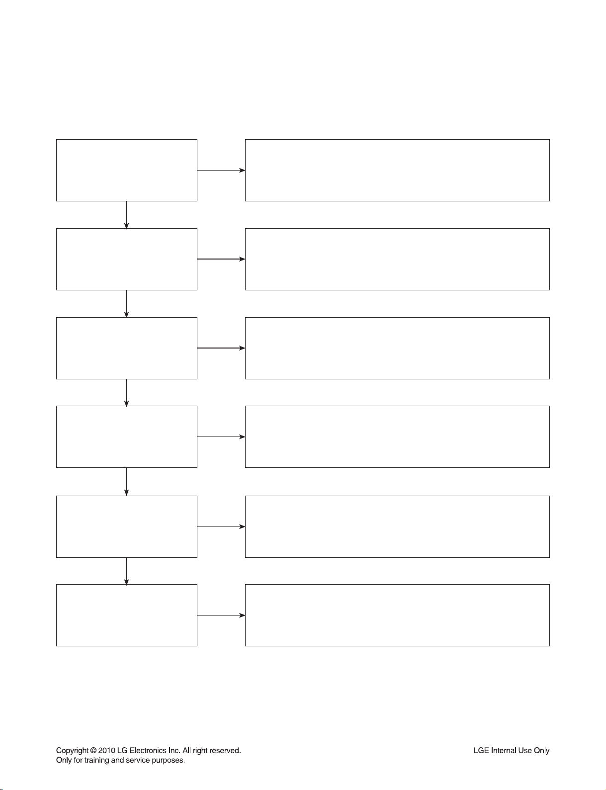
1-1. SMPS BOARD
No power.
Check the
AC line pattern.
YES
Check fuse
F900.
YES
Check C966
voltage (3.7 V)
YES
Check IC912
Vcc voltage(14V~18V).
YES
NO
NO
NO
NO
Connect the open line.
Replace F900.
Check BD900 “+” to “
Check SMPS second part lines short.
Check MAIN or AMP board short.
Replace PC900, IC960.
Check around IC910 components
(Short, Open).
-
” pin impedance.
Low impedance:
Replace IC910,
IC920, BD901.
Replace SMPS board.
No sound.
Check IC916
Vcc voltage(12V~20V).
YES
Check C952,C953
voltage(28V or -28V).
YES
Replace IC920 or SMPS board.
NO
Check no power list, AC input voltage.
NO
Check AMP module short.
Replace PC902, IC950.
2-35
Page 47

DVD SOUNDBAR TROUBLESHOOTING
1-2. FRONT BOARD
POWER cord insert.
Stand by
LED (LD304)
turn on?
YES
When you press
power key, “WELCOME”
display ok?
NO
NO
Junction
cable connection
ok?
YES
CN301
pin9 power
ok?
YES
Replace LED (LD304).
Check FRONT board.
NO
NO
Connect 40p FFC cable.
Check MAIN and
MD junction board.
YES
“WELCOME
PLEASE WAIT” Display
on LCD ok?
YES
A
NO
CN301
pin6,7,14,15 power
ok?
YES
CN301 pin2, 3, 4
data signal ok?
YES
Replace LCD.
2-36
NO
Check MD junction board.
NO
Check MAIN board.
Page 48

DVD SOUNDBAR TROUBLESHOOTING
A
When you touch
the volume key, count
is change?
YES
FRONT board ok.
NO
CN301
pin10, 11, 12 signal
ok?
YES
Check MAIN board.
NO
Replace IC301.
2-37
Page 49

DVD SOUNDBAR TROUBLESHOOTING
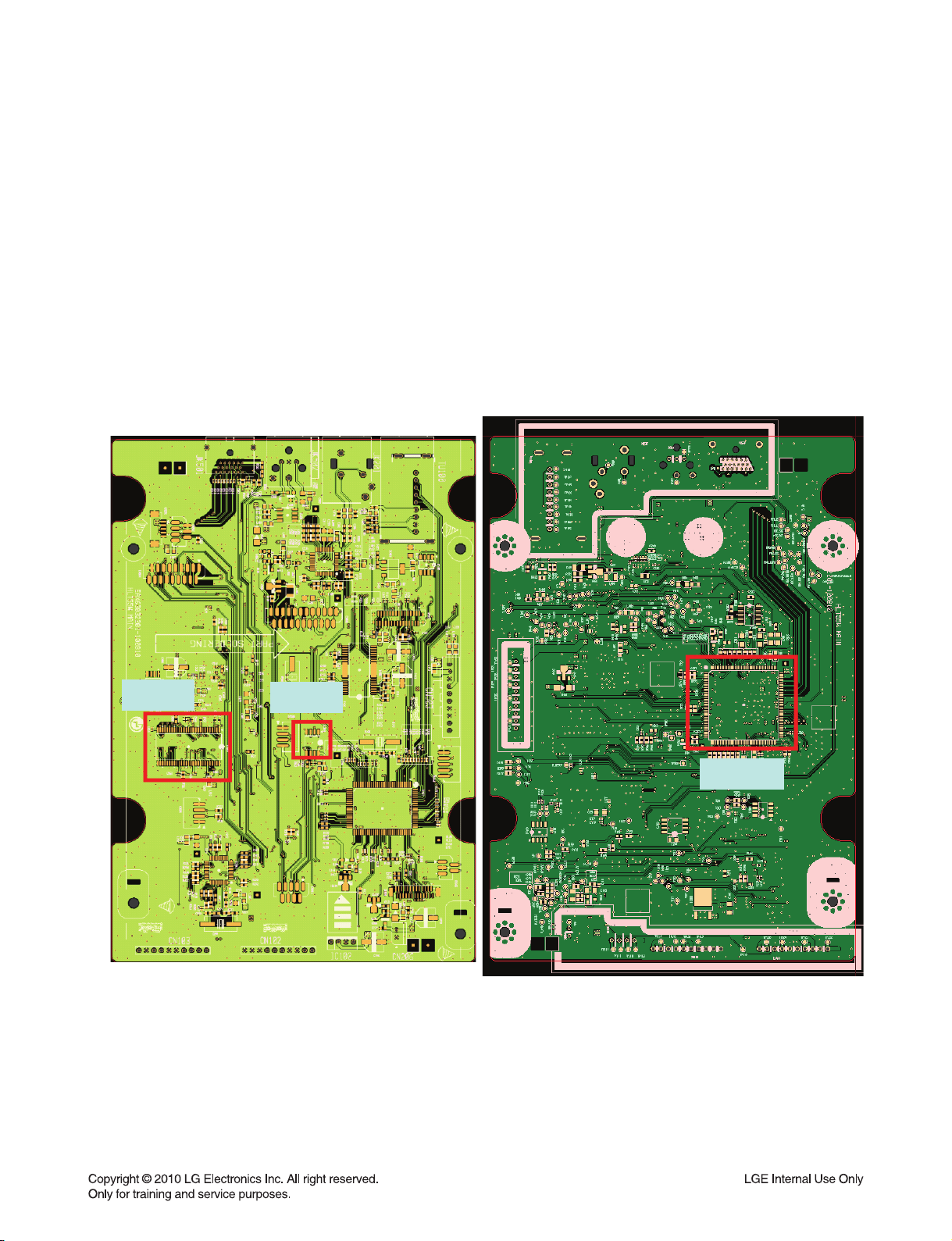
1-3. NO AUDIO CHECK
CD/DVD Disc
or USB play
YES
IC201
pin6,8,10,25 I2S
input signal
ok?
YES
IC500
pin156,157,161,162
I2S output signal
ok?
YES
A
NO
NO
Check IC500.
Check IC500.
AUX function
YES
IC200
pin7,8 audio L/R
ok?
YES
B
NO
Check JK201.
PORTABLE function
YES
IC200
pin21,22 audio L/R
ok?
YES
B
NO
Check JK303.
OPTICAL function
YES
IC501
pin29 audio signal
ok?
YES
C
NO
Check JK501.
2-38
Page 50

DVD SOUNDBAR TROUBLESHOOTING
TUNER Function
YES
IC200
audio L/R
ok?
NO
Check Tuner(TU100)
and Antenna
connection.
YES
B
IC200
pin42,43,44 I2S
clock ok?
NO
Check
IC500 and X500.
YES
IC200
pin41 I2S output
signal ok?
NO
Check IC200.
YES
C
IC505
pin7,9,18 I2S output
signal ok?
NO
Check IC505.
YES
IC201
A
pin6,8,10 I2S input
signal ok?
NO
Check
IC500 and X500.
YES
IC201
pin20,21,23,25
I2S output signal
ok?
NO
Check
IC201 and X200.
YES
AMP B/D
CN601 pin8,9,10,11
I2S signal ok?
YES
IC602,IC605
audio output signal
ok?
YES
IC701
audio output signal
ok?
YES
Check AMP IC
output stage and
CN704, CN705.
NO
NO
NO
Check 18p FFC cable
and CN601 connection.
Check
IC602 and IC605.
Check IC701.
2-39
Page 51
DVD SOUNDBAR TROUBLESHOOTING
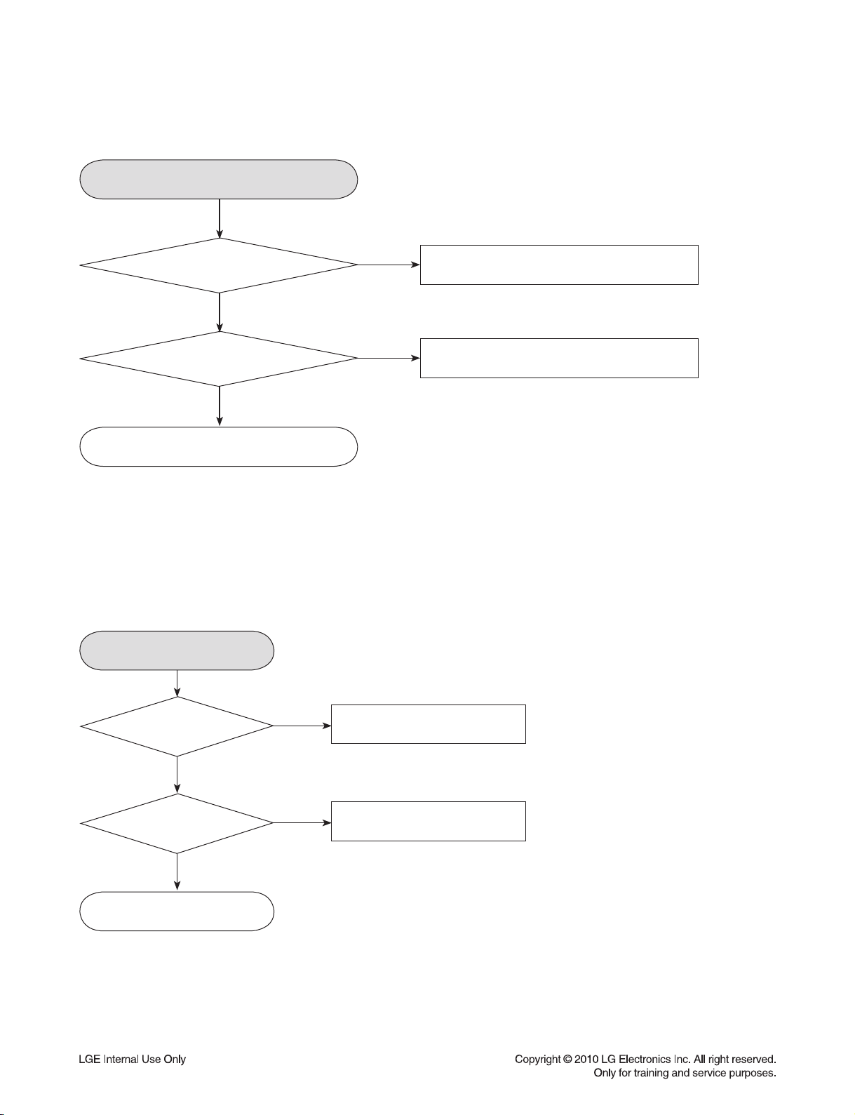
1-4. NO VIDEO CHECK
CVBS video out
IC506
pin1 video signal
ok?
YES
pin8 video signal
ok?
YES
Check JK202.
1-5. HDMI NO AUDIO/VIDEO CHECK
HDMI OUT function
NO
Check IC500.
NOIC506
Check IC506.
JK501 pin1,3,
4,6,7,9,10,12 TMDS Data
signal ok?
NO
JK501
soldering
ok?
YES
Check IC500.
YES
NO
Check JK501
and HDMI cable connection.
Resolder JK501.
2-40
Page 52

DVD SOUNDBAR TROUBLESHOOTING
1-6. SYSTEM OPERATION FLOW
POWER ON.
1. Initializes SERVO, DSP & RISC registers.
2. Write RISC code to SDRAM.
3. Reset RISC.
Show LOGO.
YES
Tray closed?
NO
Tray close to closed position.
SLED at inner
side?
NO
SLED moves to inner position.
1. Judge whether have disc and disc type.
2. Jump to related disc reading procedure.
Recieve
OPEN/ CLOSE
Key?
YES
YES
NO
NO
1. Execute Pressed Key & IR Key.
2. System operation routine loop.
1. Stop Playback & Open Tray.
2. Display tray open message & LOGO.
YES
Receive
CLOSE Key?
YES
2-41
Page 53

DVD SOUNDBAR TROUBLESHOOTING
1-7. TEST & DEBUG FLOW
TEST.
YES
Check the
AC voltage Power PCBA (110 V
or 220 V).
YES
Switch on the Power PCBA.
YES
Are the
DC Voltage outputs OK?
(from the SMPS).
YES
Are 3.7 V, 5.6 V and
12 V DC outputs normal on main
PCBA?
YES
Update
FLASH successfully?
NO
NO
NO
NO
Check the POWER PART.
Check the POWER PART.
Check the regulators or diode.
1. Check 27 MHz system clock.
2. Check system reset circuit.
3. Check FLASH R/W enable signal PRD, RWR.
4. Check FLASH Memory related circuit.
A
YES
NO
Replace FLASH.
2-42
Page 54

DVD SOUNDBAR TROUBLESHOOTING
A
YES
Power On.
YES
Show LOGO?
YES
Does Tray
move inside when it
is not at closed
position?
NO
NO
Flash
Memory operates
properly?
YES
SDRAM
works properly?
YES
MT1389FE/GH
VIDEO outputs
properly?
YES
Check AV cable
connection to TV set.
Normal
OPEN_SW,
CLOSE_SW
signal?
Check connection lines between
NO
FLASH & MT1389FE/GH and the
FLASH access time
whether is suitable or not.
NO
NO
NO
Check connection lines
between SDRAM(IC503)
& MT1389FE/GH and the
SDRAM is damaged.
Check the related circuit of
MT1389FE/GH IC500
pin139,143, 146, 146.
Check the load OPEN &
CLOSE switch.
B
YES
YES
Normal
TROPEN & TRCLOSE
signal?
YES
Normal
LOAD+ & LOAD-
signal?
YES
Check AV cable connection
between main PCBA and
loader. (MECHA)
2-43
NO
Check the Tray control IO pins
on MT1389FE/GH.
NO
Check the Tray control MOTOR &
SERVO circuit IC400.
Page 55

DVD SOUNDBAR TROUBLESHOOTING
B
YES
the SLED move to inner
Does
side when it is at outer
position?
YES
Do not put in disc
and close tray.
NO
Motor
Driver M_STBY
pin is high?
YES
Motor
Driver SLD
pin is High?
YES
SLED+ and
SLED- output
properly?
YES
Check the cable connection
with MECHA.
NO
NO
NO
Check the connection line
of M_STBY.
Check the related circuit
of SLD.
Check the amp circuit
on motor driver.
Optical Lens
has movements for
searching Focus?
YES
C
NO
Proper
Focus outputs
to motor driver?
YES
Proper F+ & F-
outputs?
YES
Check cable connection with
pick-up head.
2-44
NO
NO
Check Focus connection on
MT1389FE/GH
and motor driver.
Check the amp circuit
on motor driver.
Page 56

DVD SOUNDBAR TROUBLESHOOTING
C
YES
Laser
turns on when
reading disc?
YES
Put disc in?
YES
Disc ID is correct?
NO
NO
NO
DVDLD or
CDLD output
property?
YES
Collector
voltage of power transistor
is OK?(Q400, Q401)
YES
Check cable connection
between transistor output and
pick-up head.
Laser off.
Proper
RF signal on
MT1389FE/GH.
NO
NO
NO
Check the laser power circuit
on MT1389FE/GH and
connecting to power
transistor.(Q400, Q401)
Check the related circuit on
laser power transistor.
Check the related circuit on
MT1389FE/GH RF signal.
YES
Does spindle rotate?
YES
D
NO
YES
Check the RF connection
between S3053 and MT1389FE/GH.
Proper
SPINDLE signal on
MT1389FE/GH.
YES
SPNP
& SPNN output
properly?
YES
Check the cable connection
between spindle and main PCB.
2-45
NO
NO
Check the SPINDLE related
circuit on MT1389FE/GH.
Check the spindle control amp
circuit of motor driver.
Page 57

DVD SOUNDBAR TROUBLESHOOTING
D
YES
Focus on ok?
YES
Track On OK?
YES
NO
NO
Proper
signals on A,B,C,D of
MT1389FE/GH.
YES
Proper
CD_DVDCT signal on
MT1389FE/GH.
YES
Check CD_DVDCT connection
between S3053 and
MT1389FE/GH.
Proper
CD_DVDCT signal on
MT1389FE/GH.
YES
Proper
TRACK signal on
MT1389FE/GH.
NO
NO
NO
NO
Check connections between
MT1389FE/GH and pick-up head.
Check the related circuit on
MT1389FE/GH CD_DVDCT.
Check the related circuit on
MT1389FE/GH.
Check the TRACK connection
on MT1389FE/GH and motor driver.
Disc Playback?
YES
E
NO
YES
T+ & T-
output properly?
YES
Check cable connection
on pick-up head.
Check RF signal waveform.
2-46
NO
Check the tracking control
amp circuit on motor driver.
Page 58

DVD SOUNDBAR TROUBLESHOOTING
E
YES
Normal Audio
output when disc
playback?
YES
TEST END.
NO
IC201(Audio DSP)
received correct data
stream?
YES
Normal
Audio DSP IC out?
(IC201).
YES
Check AMP board
and 18P FFC cable.
NO
NO
Check connection between
IC500 BCK, LRCK, ADATA0,
ADATA1, ADATA2(Pins157,
158, 160, 161, 162).
Check
the related circuit of DSP
2-47
Page 59

DETAILS AND WAVEFORMS ON SYSTEM TEST AND DEBUGGING
1. SYSTEM 27 MHz CLOCK,RESET,FLASH R/W SIGNAL
1)
MT1389FE/GH
2)
MT1389FE/GH
Power Cord in
main clock is at 27 MHz(X500)
1
1
FIG 1-1
reset is high active.
P_CTL
DVD_RST
RESET_IN
IC101
2
2
3
4
IC101
FIG 1-2
IC500
^
3
2-48
4
Page 60
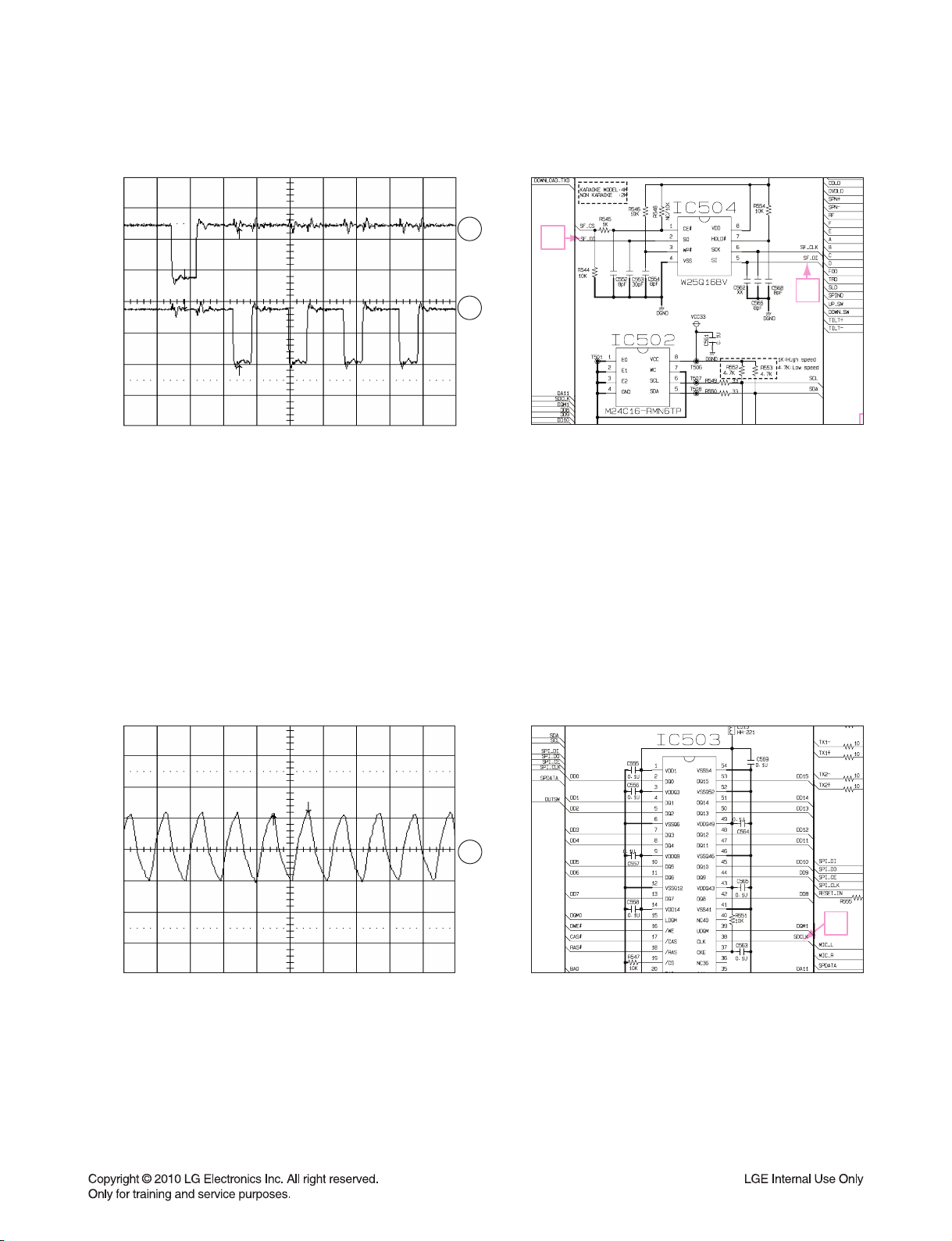
3) Flash R/W enable signal during download(Downloading)
SF_DI
SF_DO
FIG 1-3
2. SDRAM CLOCK
5
6
6
5
1)
MT1389FE/GH
DCLK = 93 MHz, Vp-p = 2.2, Vmax = 2.7 V
SDCLK
main clock is at 27 MHz(X500)
7
7
FIG 2-1
2-49
Page 61

3. VIDEO PART-1 (100% FULL COLOR-BAR)
8
CVBS_I
8
4. VIDEO PART-2 (100% FULL COLOR-BAR)
9
CVBS
9
2-50
Page 62

5. HDMI PART
10
11
10 11
12
13
HDMI_SDA
HDMI_SCL
12 13
HDMI_CLK HDMI_DATA
2-51
Page 63

6. SERVO OPEN/CLOSE SIGNAL
1) Tray open/close waveform
OUTSW
IN_SW
OPEN
14
15
16
CLOSE
FIG 3-1
2) Tray close waveform
OUTSW
IN_SW
OPEN
CLOSE
FIG 3-2
3) Tray open waveform
17
15 14
SERVO
14
15
16
17
OUTSW
IN_SW
OPEN
CLOSE
17
14
16
15
16
17
FIG 3-3
2-52
Page 64

4) SLED CONTROL RELATED SIGNAL (NO DISC CONDITION)
SLD
M-STBY
SL+
SL-
FIG 4-1
18
19
20
21
18
19
2120
2-53
Page 65

5) LENS CONTROL RELATED SIGNAL(NO DISC CONDITION)
FOD
F+
F-
FIG 5-1
22
23
24
22
23 24
IC400
6) LASER POWER CONTROL RELATED SIGNAL(NO DISC CONDITION)
IC500
MDI1
DVDLD
CDLD
FIG 6-1
25
26
27
25 27 26
2-54
Page 66

7) DISC TYPE JUDGEMENT WAVEFORMS
F+
PU_DET
RF
FIG 7-1 (DVD)
F+
PU_DET
28
29
30
28
29
28
29 : This signal can see using special debug program
IC400
IC500
^
FIG 7-2 (DVD)
RF
30
30
29
2-55
Page 67

F+
28
PU_DET
RF
F+
PU_DET
RF
FIG 7-3 (CD)
29
30
28
29
30
28
29 : This signal can see using special debug program
IC400
IC500
^
29
FIG 7-4 (CD)
30
2-56
Page 68

8) FOCUS ON WAVEFORMS
31 : This signal can see using special debug program
PU_DET
FOD
F+
F-
PU_DET
FOD
F+
F-
FIG 8-1 (DVD)
31
32
33
34
31
32
33
34
32
IC500
^
31
IC400
FIG 8-2 (CD)
33
IC400
34
2-57
Page 69

9) SPINDLE CONTROL WAVEFORMS (NO DISC CONDITION)
FIG 9-1
SPIND
35
SP-
36
SP+
37
2-58
35
36 37
Page 70

10) TRACKING CONTROL RELATED SIGNAL(System checking)
38 : This signal can see using special debug program
PU_DET
PU_DET
38
TRO
TRO
39
IC500
^
T-
T+
T-
T+
PU_DET
TRO
FIG 10-1(DVD)
FIG 10-2(CD)
PU_DET
TRO
T-
T+
40
41
38
39
40
41
38
39
IC400
4140
2-59
Page 71

MEMO
2-60
Page 72

z
WIRING DIAGRAM
1. DVD SOUNDBAR WIRING DIAGRAM
~pylslzz
tvk|sl
qhjr
tpj w{i |zi
juZWXGGG
^
wGmmj
\
wpu
juZWYG
GGG
zwr qhjr
G
htw
XWGwpu
ju]WYGGGG
_
X
wpu
ju]WXGGGG
{|ulyG
h|G
pu
vw{Gpu
}ppklv
v|{V
oktp
v|{
juYWYGGGGGG
^wGmmj
\Gw
juYW\GGGGGG
j
uXWXGGG
Z
W
wGGmmj
Y
Z
wG mmj
ju[WWGGG
X_
wpu
pu
ju\W[GGGGGG
G
XWGwpu
ju\WZGGGGG
juYW[GGGGGG
thpuGGG
Y]
wGGmmj
YGw
juYW]GGGGGG
ju`WYGGGGG
juXWYGGGGG
juXWZGGGGG
ju`WXGGGG
mhuG
thpuG ztwzGG
XW
wpuG
z
twzGG
w~y jvyk
wu`WW
tkGG
X]
wpu
juZWXGGGG
2-622-61
myvu{
Page 73

BLOCK DIAGRAMS
1. DVD SOUNDBAR BLOCK DIAGRAMS
1-1. MAIN BLOCK DIAGRAM
AUX
TUNER
Portable
HDMI
OUT
USB
AUX AUDIO
TUNER AUDIO
PORT AUDIO
CEC_TX/RX
MP_HDMI_SCL
MP_HDMI_SDA
TX_MPEG(0,1,2,C)
D+, D-
CS5346
(ADC)
EEPROM
I2C/RST
MCLK/BCK/LRCK
SP_DATA
SCL
SDA
DVD_RESET
SANYO
MICOM
(100Pin)
DVD_RX
27 MHz
9.8304 MHz
AUDIO
DVD_TX
DSP/SF_CLK
DSP/SF_DI
DSP/SF_DO
DSP_BSY/IRQ
DSP_RST
SF_CE
DSP_CE
FLASH
CS48560
MCLK/BCK/LRCK
FL/FR(ADATA0)
RL/RR(ADATA1)
C/W(ADATA2)
DSP
Volume CTL
EQ
Ch Delay
B/M
I2S
244
FL
FR
C
W
RL
RR
PWM IC
PS9850
AMP_PDN_L
AMP_PROTECT
OTW
DCP_L
LPF
MICOM CTL(I2C)
LCD_CLK/STB/DO
LPF
PWMPWM
IRS2093
I2S(RL/RR/W)
W/TX
Module
LCD
OPT IN
MIC
Composite
SPDIF IN
MIC L/R
CVBS
S4308
TH7314
DMA[0-10]
SDRAM
MTK1389GH
(176PIN)
DB[0-15]
SF_CS
SF_CLK
FLASH
SF_DI/DO
SCL
SDA
EEPROM
A, B, C, D, E, F, RF
MD_DVD, MD_CD,LD_DVD, LD_CD,VR_DVD, VR_CD
FOCUS/SLED/SPINDLE/TRACKING
TILTO+/TILTO-
UP/DOWN_SW
OPEN/CLOSE
IN/OUT_SW
S8082
Motor
Drive
S3053
F+/-, T+/-
SLED+/SPINDLE+/-
PICK-UP
(Sanyo/IM)
Motor
S8082
TILT+/TILT-
Lift
Motor
LOAD+/-
Open/Close
Motor
2-642-63
Page 74

DVD SOUNDBAR BLOCK DIAGRAMS
1-2. FRONT / SMPS BLOCK DIAGRAM
mmyvu{
m
t
pYz
sjk
pYz
ztwz
m
t
j
Y[
j
{
Gp
_jYWZ
RY`G}SGTY`G}SGTX^G}
tGw
ji
RZU^G}SGRXYG}SGR\U]G}SGT\G}
2-662-65
Page 75

2. WIRELESS SUBWOOFER BLOCK DIAGRAM
9.8304 MHz
SCL
PWM_RST
PWM_I2C
PWM IC
WOOFER
LPF
PWM
AMP IC
EEPROM
WL_SDA/SCL/RST/EN
WL_LINK/BUSY/INITIAL
SDA
WP
SANYO
AUDIO
MICOM
(100Pin)
27 MHz
PS9850
MCLK/BCK/LRCK
FL/FR(ADATA0)
RL/RR(ADATA1)
C/W(ADATA2)
REAR
TAS5612
LPF
PWM
AMP IC
TAS5612
W/TX
MODULE
LED CTL
BLUE/RED LED
2-682-67
Page 76

CIRCUIT DIAGRAMS
1. DVD SOUNDBAR CIRCUIT DIAGRAMS
1-1. SMPS - POWER CIRCUIT DIAGRAM
12
11
10
9
8
IMPORTANT SAFETY NOTICE
WHEN SERVICING THIS CHASSIS, UNDER NO
CIRCUMSTANCES SHOULD THE ORIGINAL DESIGN
BE MODIFIED OR ALTERED WITH OUT PERMISSION
FROM THE LG CORPORATION. ALL COMPONENTS
SHOULD BE REPLACED ONLY WITH TYPES
IDENTICAL TO THOSE IN THE ORIGINAL CIRCUIT.
SPECIAL COMPONENTS ARE SHADED ON THE
SCHEMATIC FOR EASY IDENTIFICATION.
THIS CIRCUIT DIAGRAM MAY OCCASIONALLY
DIFFER FROM THE ACTUAL CIRCUIT USED. THIS
WAY, IMPLEMENTATION OF THE LATEST SAFETY
AND PERFORMANCE IMPROVEMENT CHANGES
INTO THE SET IS NOT DELAYED UNTIL THE NEW
SERVICE LITERATURE IS PRINTED.
NOTE :
1. Shaded( ) parts are critical for safety. Replace only
with specified part number.
2. Voltages are DC-measured with a digital voltmeter
during Play mode.
7
6
5
4
3
2
CAUTION:
Danger if fuse is incorrectly replaced.
Replace only with the type identical to fuse rating
1
A
and(or) model name described in main label.
B C D E F G H I J K L M N O P Q R ST
Warning
Parts that are shaded are critical with
respect to risk of fire or electrical shock.
EBY60948901, REV4.1
SMPS
2010. 08. 12
2-702-69
Page 77

DVD SOUNDBAR CIRCUIT DIAGRAMS
1-2. MAIN - MPEG CIRCUIT DIAGRAM
12
11
6
10
9
5
10 11
8
12
7
6
13
1
5
7
4
3
25 27 26 29
2
31
38
1
: WAVEFORM NUMBER
A
B C D E F G H I J K L M N O P Q R ST
4
8 9
EBY60928801(#1), REV5.2
MPEG
2010. 08. 12
2-722-71
Page 78

DVD SOUNDBAR CIRCUIT DIAGRAMS
1-3. MAIN - SERVO CIRCUIT DIAGRAM
12
11
10
9
8
30
221832
39
19
35
7
2120
36 37
6
23
24
28
34
5
4
33
4140
17
3
16
15 14
2
1
: WAVEFORM NUMBER
A
B C D E F G H I J K L M N O P Q R ST
EBY60928801(#2), REV5.2
SERVO
2010. 08. 12
2-742-73
Page 79

DVD SOUNDBAR CIRCUIT DIAGRAMS
1-4. MAIN - ADC / DSP / INTERFACE CIRCUIT DIAGRAM
12
11
10
9
8
7
6
5
4
3
2
1
A
B C D E F G H I J K L M N O P Q R ST
ADC / DSP / INTERFACE
EBY60928801(#3), REV5.2
2010. 08. 12
2-762-75
Page 80

DVD SOUNDBAR CIRCUIT DIAGRAMS
1-5. MAIN - MICOM CIRCUIT DIAGRAM
12
11
10
9
8
7
6
2
5
4
3
3
2
1
: WAVEFORM NUMBER
A
B C D E F G H I J K L M N O P Q R ST
EBY60928801(#4), REV5.2
MICOM
2010. 08. 12
2-782-77
Page 81

DVD SOUNDBAR CIRCUIT DIAGRAMS
1-6. AMP - PWM CIRCUIT DIAGRAM
12
11
10
9
8
7
6
5
4
3
2
1
EBY60931401(#1), REV5.2
A
B C D E F G H I J K L M N O P Q R ST
PWM
2010. 08. 12
2-802-79
Page 82

DVD SOUNDBAR CIRCUIT DIAGRAMS
1-7. AMP - SMPS & AMP CIRCUIT DIAGRAM
12
11
10
9
8
7
6
5
4
3
2
1
EBY60931401(#2), REV5.2
A
B C D E F G H I J K L M N O P Q R ST
AMP
2010. 08. 12
2-822-81
Page 83

DVD SOUNDBAR CIRCUIT DIAGRAMS
1-8. FRONT - FRONT / TOUCH CIRCUIT DIAGRAM
12
11
10
9
8
7
6
5
4
3
2
1
EBY60931501, REV4.2
A
B C D E F G H I J K L M N O P Q R ST
FRONT
2010. 08. 12
2-842-83
Page 84

DVD SOUNDBAR CIRCUIT DIAGRAMS
1-9. JACK - MIC / USB / PTB CIRCUIT DIAGRAM
12
11
10
9
8
7
6
5
4
3
2
1
EBY60931601, REV3.3
A
B C D E F G H I J K L M N O P Q R ST
JACK
2010. 08. 12
2-862-85
Page 85

CIRCUIT DIAGRAMS
2. WIRELESS SUBWOOFER CIRCUIT DIAGRAMS
2-1. SMPS - POWER CIRCUIT DIAGRAM
12
11
10
9
8
IMPORTANT SAFETY NOTICE
WHEN SERVICING THIS CHASSIS, UNDER NO
CIRCUMSTANCES SHOULD THE ORIGINAL DESIGN
BE MODIFIED OR ALTERED WITH OUT PERMISSION
FROM THE LG CORPORATION. ALL COMPONENTS
SHOULD BE REPLACED ONLY WITH TYPES
IDENTICAL TO THOSE IN THE ORIGINAL CIRCUIT.
SPECIAL COMPONENTS ARE SHADED ON THE
SCHEMATIC FOR EASY IDENTIFICATION.
THIS CIRCUIT DIAGRAM MAY OCCASIONALLY
DIFFER FROM THE ACTUAL CIRCUIT USED. THIS
WAY, IMPLEMENTATION OF THE LATEST SAFETY
AND PERFORMANCE IMPROVEMENT CHANGES
INTO THE SET IS NOT DELAYED UNTIL THE NEW
SERVICE LITERATURE IS PRINTED.
NOTE :
1. Shaded( ) parts are critical for safety. Replace only
with specified part number.
2. Voltages are DC-measured with a digital voltmeter
during Play mode.
7
6
5
4
3
2
Warning
Parts that are shaded are critical with
CAUTION:
Danger if fuse is incorrectly replaced.
1
Replace only with the type identical to fuse rating
and(or) model name described in main label.
A
B C D E F G H I J K L M N O P Q R ST
respect to risk of fire or electrical shock.
EBY60891701, REV6.1
SMPS(WF)
2010. 08. 12
2-882-87
Page 86

WIRELESS SUBWOOFER CIRCUIT DIAGRAMS
2-2. AMP - AMP1 CIRCUIT DIAGRAM
12
11
10
9
8
7
6
5
4
3
2
1
EBY60931701(#1), REV3.2
A
B C D E F G H I J K L M N O P Q R ST
AMP(WF)
2010. 08. 12
2-902-89
Page 87

WIRELESS SUBWOOFER CIRCUIT DIAGRAMS
2-3. AMP - AMP2 CIRCUIT DIAGRAM
12
11
10
9
8
7
6
5
4
3
2
1
EBY60931701(#2), REV3.2
A
B C D E F G H I J K L M N O P Q R ST
AMP(WF)
2010. 08. 12
2-922-91
Page 88

WIRELESS SUBWOOFER CIRCUIT DIAGRAMS
2-4. KEY CIRCUIT DIAGRAM
12
11
10
9
8
MEMO
7
6
5
4
3
2
1
EBY61051301, REV2.1
A
BCDEFGH I J
KEY(WF)
2010. 08. 12
2-942-93
Page 89

CIRCUIT VOLTAGE CHART
1. MAIN BOARD
Type Pin
IC100 EEPROM(Micom)
MC24C16
VCC: 8 VCC: +1.8 ~ +5.5V VCC: +3.37TYPE: 8P SO-8
VENDER: STM
IC101 MICOM
LC87F5ND0C
VDD: 14,40,55,89 VDD: +3.0 ~ +3.6V VDD: +3.38TYPE: 100P LQFP
VENDER: SANYO
IC102 Voltage Regulator
KIA278R33
VCC(OUT): 2 VCC(IN): Max +18V VCC33: +3.28TYPE: 4P TO200IS
VENDER: KEC CORP.
IC103 Voltage Regulator
KIA1117AF
VCC(OUT): 2 VCC(IN): Max +10V VCC33: +1.811TYPE: 3P SOT-223
VENDER: KEC CORP.
IC107 LDO
TJ3965D-ADJ
TYPE: 80 SOP
VENDER:
TAEJIN TECHNOLOGY
CS5346 VA: 14 VA: +3.1 ~ +5.25V VA: +5.03
TYPE: 48P LQFP VD: 46 VD: +3.1 ~ VA+0.25 or +5.25V VD: +3.27
VENDER:
CIRRUS LOGIC
CS48560 VDD: 16,28,42 VDD: +1.62 ~ +1.98V VDD: +1.78
TYPE: 48P LQFP VDDA: 48 VDDA: +3.0 ~ +3.6V VDDA: +3.28
VENDER: CIRRUS LOGIC VDDI: 12,24,37 VDDI: +3.0 ~ +3.6V VDDI: +3.28
MX25L1605DM2I-12G
TYPE: 8P SOP
VENDER:
MACRONIX INTERNATIONAL
THS7314DR
TYPE: 8P SOIC
VENDER:
TEXAS INSTRUMENTS
VCC(OUT): 3 VCC: Max +15V VOUT: +5.1
IC200 ADC
VLS: 36 VLS: +1.71 ~ +5.25V VLS: +3.27
VLC: 5 VLC: +1.71 ~ +5.25V VLC: +3.27
IC201 Audio DSP
IC202 Flash ROM(DSP)
VDD: 8 VDD: +2.7 ~ +3.6V VDD: +3.28
IC206 Video Amplifi er
VS+: 4P VS+ : +3.0 ~ +5.0V VS+: +3.29
Spec ACTUAL measurement
Vcc/Vdd
Type Pin
IC400 SERVO
S3053
VCC: 8,19 VCC: +4.5 ~ +5.5V VCC: +5.11TYPE: 28P HSOP
VENDER:AUK CORP
IC401 MOTOR IC
S8082
VCC(OUT): 6,7 VCC: Max +18V VOUT: +7.01TYPE: SOP8
VENDER: AUK
IC402 LDO
AZ1117BH
VCC(OUT): 2 VCC: Max +18V VOUT: +11.9TYPE: SOT223
VENDER: BCD
IC500 MPEG
MT1389FE/GH AVDD18: 1,25,165 AVDD18: +1.08 ~ +1.32V AVDD: +1.25
TYPE: 176P LQFP DVDD18: 79,109 DVDD18: +1.08 ~ +1.32V DVDD: +1.24
VENDER:
MEDIATEK INCORPORATION
MC24C16
VENDER: STM
V54C3128164
TYPE: 54P TSOP
VENDER:
PROMOS TECHNOLOGIES
MX25L3205DM2I-12G
TYPE: 8P SOP
VENDER:
MACRONIX INTERNATIONAL
74AHC244
TYPE: 20P TSSOP
VENDER:
NXP SEMICONDUCTORS
DVDD33: 38,57,67,92,101 DVDD33: +3.0 ~ +3.6V DVDD33: +3.28
AVDD33: 2,140,142 AVDD33: +3.0 ~ +3.6V AVDD33: +3.27
IC502 EEPROM(Mpeg)
VCC: 8 VCC: +1.8 ~ +5.5V VCC: +3.31TYPE: 8P SO-8
IC503 SDRAM
VCC: 1,3,9,14,27,43,49 VCC: +3.0 ~ +3.6V VCC: +3.28
IC504 Flash ROM(Mpeg)
VDD: 8 VDD: +2.7 ~ +3.6V VDD: +3.31
IC505 CMOS
VCC: 20 VCC: -0.5 ~ +7.0V VCC: +3.27
Spec ACTUAL measurement
Vcc/Vdd
2-962-95
Page 90

2. AMP BOARD
MEMO
Type Pin
PS9850
VENDER: PULSUS
MC4580
IRS2093
TYPE: MLPQ 48P
VENDER:
INTERNATIONAL RECTIFIER
3. FRONT BOARD
Type Pin
CY8C20324
VENDER: CYPRESS
Vcc/Vdd
Spec ACTUAL measurement
IC602 PWM IC
VDD_IO : 16,24,29,32,35,40,48 VDD: +2.97 ~ +3.63V VDD: +3.27TYPE: 64P TQFP
IC601,603 OPAMP
VDD : 3 VDD: +4.87
VEE : 8 VEE:-4.98
IC701 IR AMP IC
VDD: 16 VDD: +215 VDD: -15.74
Vcc/Vdd
Spec ACTUAL measurement
IC301 Touch IC
VCC(OUT): 20 VCC: Max +6V VOUT: +3.35TYPE: QFN 24P
4. JACK BOARD
Type Pin
TJ3965D-ADJ
TYPE: 80 SOP
VENDER:
TAEJIN TECHNOLOGY
S4308
VENDER: AOK
Vcc/Vdd
Spec ACTUAL measurement
IC301 LDO
VCC(OUT): 3 VCC: Max +15V VOUT: +5.03
IC302 MIC IC
VCC(OUT): 6 VCC: Max +15V VOUT: +11.47TYPE: SOT-26
2-982-97
Page 91

PRINTED CIRCUIT BOARD DIAGRAMS
1. DVD SOUNDBAR P. C. BOARD
1-1. SMPS P. C. BOARD
(TOP VIEW) (BOTTOM VIEW)
NOTE) Warning
Parts that are critical with respect to risk
of fire or electrical shock.
2-1002-99
Page 92
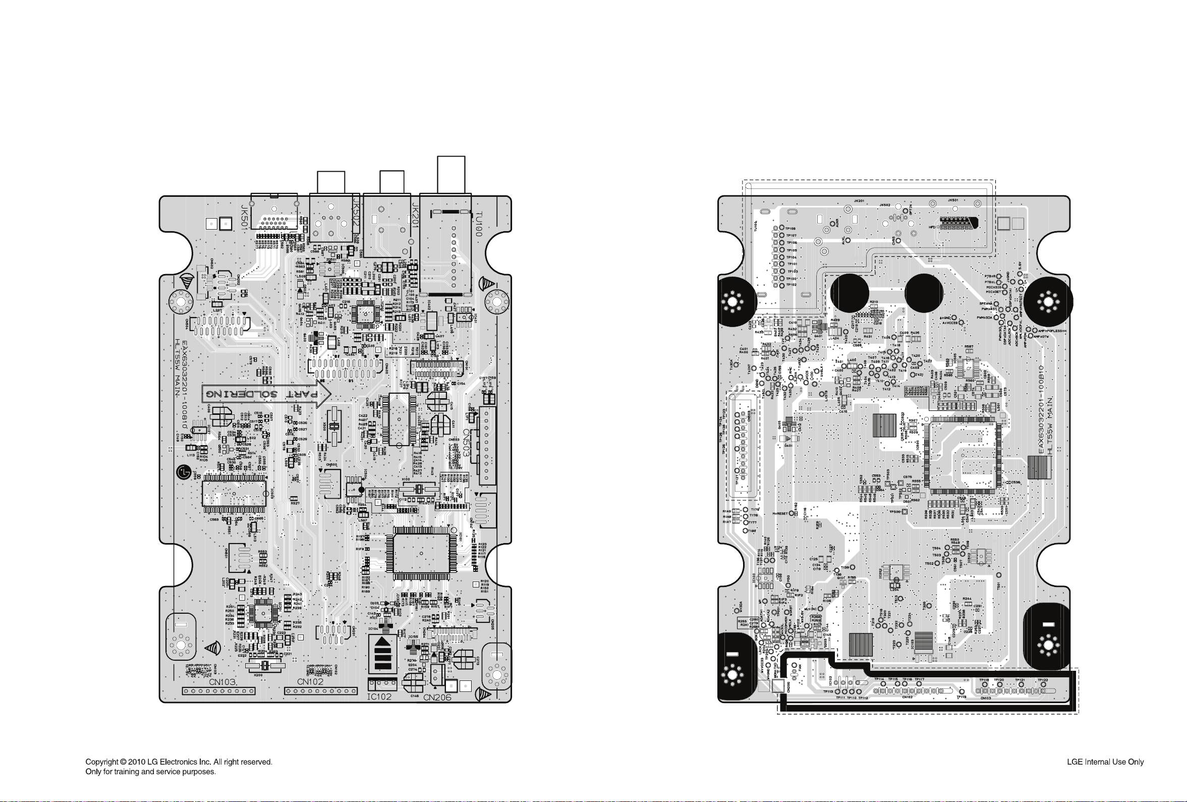
DVD SOUNDBAR P. C. BOARD
1-2. MAIN P. C. BOARD
(TOP VIEW)
(BOTTOM VIEW)
2-1022-101
Page 93

DVD SOUNDBAR P. C. BOARD
1-3. AMP P. C. BOARD
(TOP VIEW) (BOTTOM VIEW)
2-1042-103
Page 94

DVD SOUNDBAR P. C. BOARD
1-4. FRONT P. C. BOARD
(TOP VIEW) (BOTTOM VIEW)
2-1062-105
Page 95

DVD SOUNDBAR P. C. BOARD
1-5. JACK P. C. BOARD
(TOP VIEW) (BOTTOM VIEW)
2-1082-107
Page 96

PRINTED CIRCUIT BOARD DIAGRAMS
2. WIRELESS SUBWOOFER P. C. BOARD
2-1. SMPS P. C. BOARD
(TOP VIEW) (BOTTOM VIEW)
Warning
Parts that are shaded are critical with
respect to risk of fire or electrical shock.
2-1102-109
Page 97

WIRELESS SUBWOOFER P. C. BOARD
2-2. AMP P. C. BOARD
(TOP VIEW) (BOTTOM VIEW)
2-3. KEY P. C. BOARD
(TOP VIEW) (BOTTOM VIEW)
2-1122-111
Page 98

SECTION 3
CABINET & MAIN CHASSIS
CONTENTS
EXPLODED VIEWS ......................................................................................................................................... 3-3
1. DVD SOUNDBAR SECTION .................................................................................................................... 3-3
1-1. CABINET AND MAIN FRAME EXPLODED VIEW .............................................................................. 3-3
1-2. DECK MECHANISM EXPLODED VIEW (SDP07) .............................................................................. 3-5
2. WIRELESS SUBWOOFER SECTION ...................................................................................................... 3-7
3. PACKING ACCESSORY SECTION ......................................................................................................... 3-9
3-1
Page 99

MEMO
3-2
Page 100

EXPLODED VIEWS
1. DVD SOUNDBAR SECTION
1-1. CABINET AND MAIN FRAME EXPLODED VIEW
C
282L
A50
A
NOTES) THE EXCLAMATION POINT WITHIN AN
EQUILATERAL TRIANGLE IS INTENDED
TO ALERT THE SERVICE PERSONNEL
B
TO THE PRESENCE OF IMPORTANT
SAFETY INFORMATION IN SERVICE
LITERATURE.
A48
A
284
280
281
457
465
468
A45
K
282R
AMP
FRONT
KEY
L
M
464
D
E
287
464
283
285L
454
D
E
CABLE3
CABLE4
464
I
498
F
G
286
285R
A46
B
C
K
F
I
H
470
O
L
M
O
CABLE1
CABLE2
WIRELESS
260
468
A54
270
MAIN
N
G
N
272
454
A44
265
H
498
452
POWER
464
A47
261
468
J
452
J
300
288
468
3-43-3
 Loading...