

LG HBLG1004R, HBLG8004RA4, HBLG8004R, HBLG8004RB4, L8004RY4 Service Manual
...
LG
Room
Air Conditioner
SERVICE MANUAL
LG
CAUTION
website http://www.lgservice.com
• BEFORE SERVICING THE UNIT, READ THE SAFETY
PRECAUTIONS IN THIS MANUAL.
• ONLY FOR AUTHORIZED SERVICE PERSONNEL.
MODEL: HBLG8004R,HBLG8004RA4,HBLG8004RB4,
HBLG1004R, CL8000ER,M8004R, M8004RY4,
M1004R,L8004R,L8004RY4,L1004R

2 Room Air Conditioner
Air Conditioner Service Manual
TABLE OF CONTENTS
Safety Precautions..........................................................................................................................................3
Dimensions .....................................................................................................................................................6
Outside Dimensions...................................................................................................................................6
Product Specifications ..................................................................................................................................7
Installation .......................................................................................................................................................8
Select the Best Location ............................................................................................................................8
Installation Check.......................................................................................................................................8
How to Secure the Drain Pipe....................................................................................................................8
How to Install..............................................................................................................................................9
Operation ......................................................................................................................................................12
Function of Controls .................................................................................................................................12
Disassembly..................................................................................................................................................13
Mechanical Parts......................................................................................................................................13
Air handling Parts.....................................................................................................................................14
Electrical Parts .........................................................................................................................................15
Refrigerating Cycle...................................................................................................................................17
Schematic Diagram.......................................................................................................................................20
Electronic Control Device.........................................................................................................................20
Wiring Diagram.........................................................................................................................................21
Components Location ..............................................................................................................................22
Troubleshooting Guide.................................................................................................................................23
Pipeing System ........................................................................................................................................23
Trou
bleshooting Guide .............................................................................................................................24
Elect
rical Parts Troubleshooting Guide ....................................................................................................26
Electrical Parts .........................................................................................................................................30
Exploded View ..............................................................................................................................................36
Replacement Parts List ................................................................................................................................37
Service Manual 3
Safety Precautions
Safety Precautions
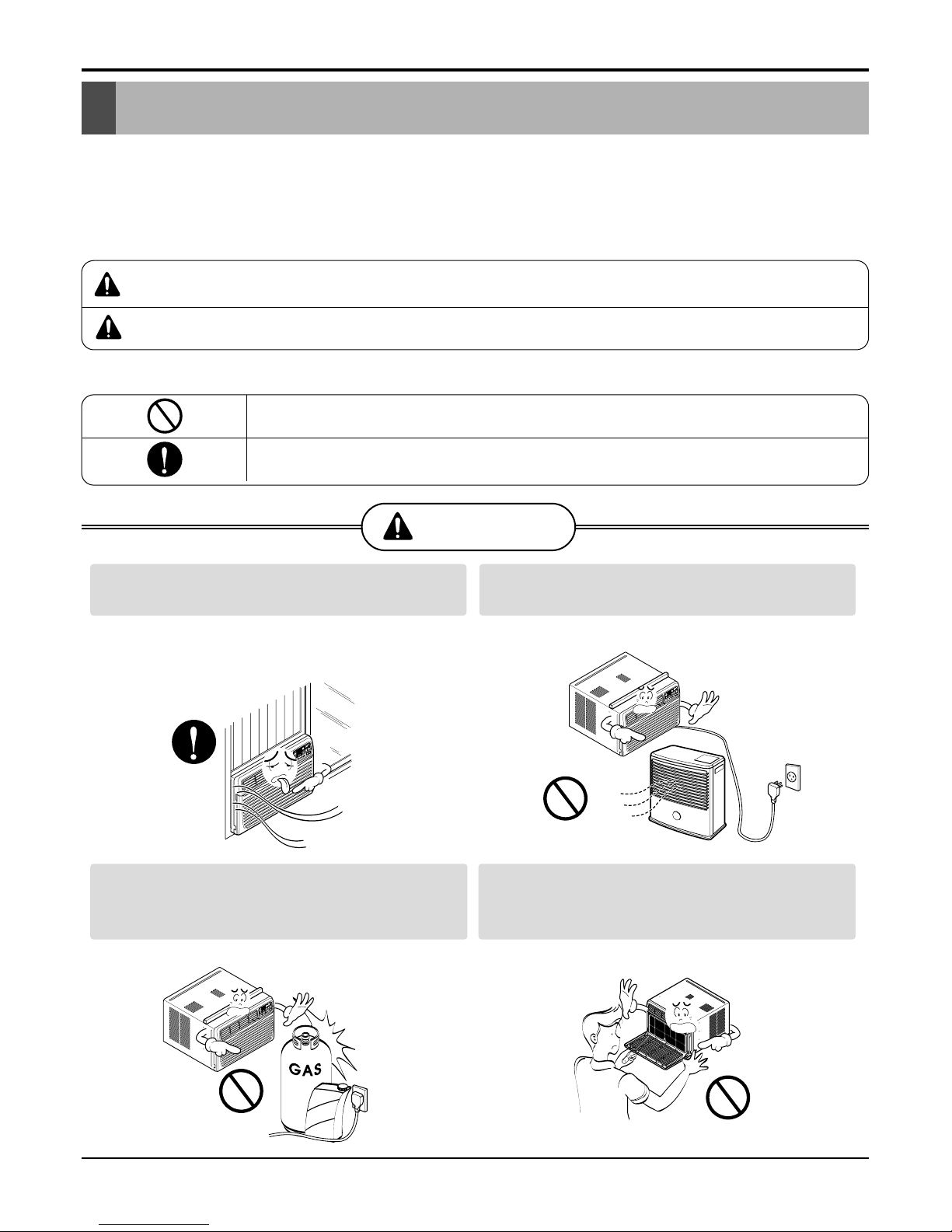
To prevent injury to the user or other people and property damage, the following instructions must
be followed.
■ Incorrect operation due to ignoring instruction will cause harm or damage. The seriousness is
classified by the following indications.
■ Meanings of symbols used in this manual are as shown below.
WARNING
CAUTION
This symbol indicates the possibility of death or serious injury.
This symbol indicates the possibility of injury or damage to property only.
Be sure not to do.
Be sure to follow the instruction.
WARNING
Always install the expansion panel(s).
• Improper assembly or installation may cause
incorrect operation, including injury, fire, and
electric shock hazards.
Do not place the power cord near a heater.
• It may cause fire and electric shock.
Do not use the power cord near flammable
gas or combustibles such as gasoline,
benzene, thinner, etc.
• It may cause explosion or fire.
Do not disassemble or modify products.
• It may cause electric shock and failure.
Gasolin
4 Room Air Conditioner
Safety Precautions
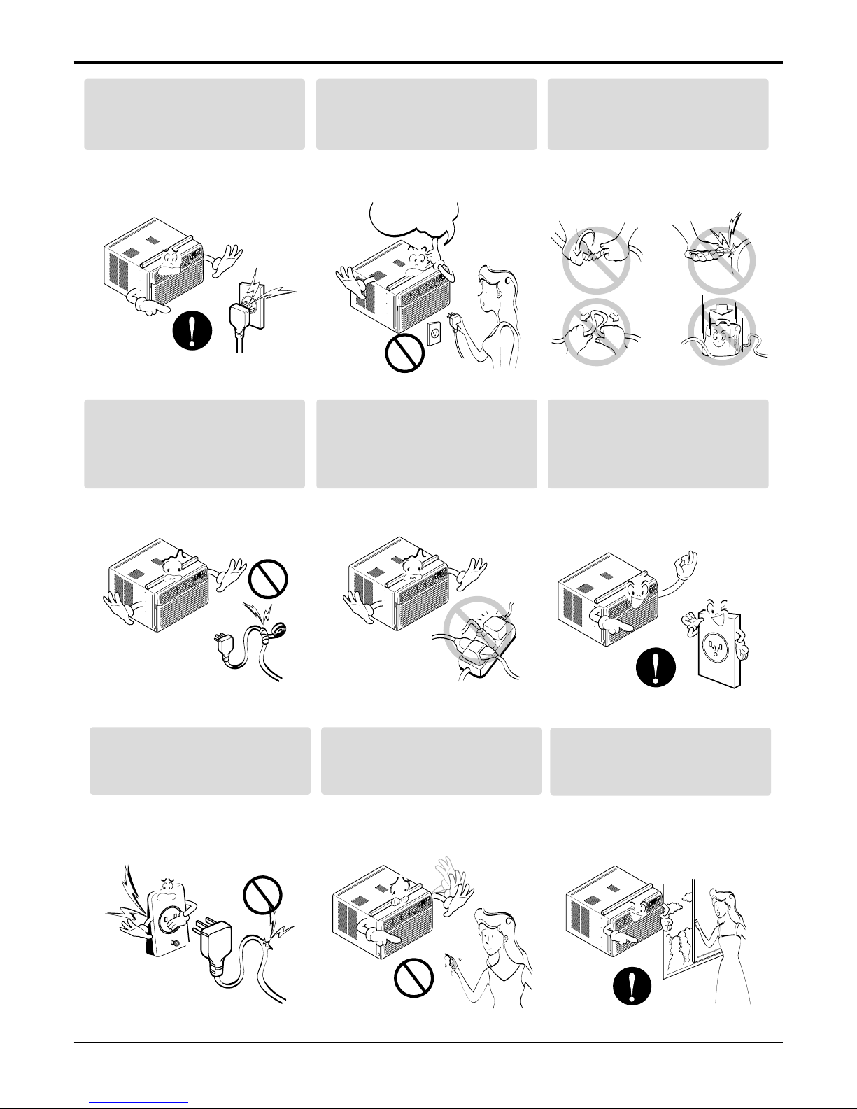
Plug in the power plug
properly.
• Otherwise, it will cause
electric shock or fire.
Do not operate or stop the
unit by inserting or pulling
out the power plug.
• It will cause electric shock or
fire.
Do not damage or use an
unspecified power cord.
• It will cause electric shock or
fire.
Do not modify power cord
length.
• It will cause electric shock or
fire.
Use the air conditioner on a
single outlet circuit.
Do not share the outlet with
other appliances.
• It will cause electric shock or
fire.
Always plug into a
grounded outlet.
• No grounding may cause
electric shock.
Do not use the socket if it is
loose or damaged.
• It may cause fire and electric
shock.
Do not operate with wet
hands or in damp
environment.
• It may cause electric shock.
ON
ON
Ventilate before operating air
conditioner when gas goes
out.
• It may cause explosion, fire,
and burn.
Service Manual 5
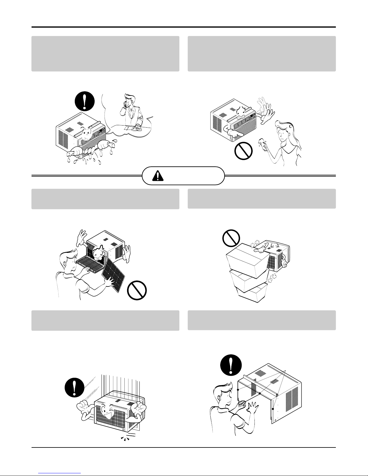
If water enters the product, turn off the the power
switch of the main body of appliance. Contact service center after taking the power-plug out from
the socket.
• It will cause electric shock or failure of machine.
Do not clean the air conditioner with water.
• Water may enter the unit and degrade the insulation. It may cause an electric shock.
Never touch the metal parts of the unit when
removing the filter.
• They are sharp and may cause injury.
Do not block the inlet or outlet.
• It may cause failure of appliance or performance
deteriorate.
Ensure that the outer case is not damaged by
age or wear.
• If the outer case is damaged, it must be repaired
or replaced immediately.
Leaving it damaged could result in the air conditioner falling out of the window, creating a safety
hazard.
Be cautious not to touch the sharp edges
when installing.
• It may cause injury.
CAUTION
Safety Precautions
Sharp
edges
6 Room Air Conditioner
Dimensions
Dimensions
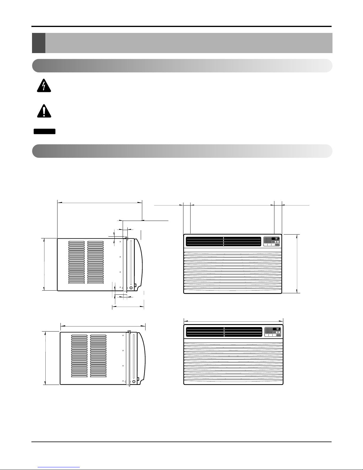
Outside Dimensions
This symbol alerts you to the risk of electric shock.
This symbol alerts you to hazards that could cause harm to the
air conditioner.
This symbol indicates special notes.
NOTICE
Symbols Used in this Manual
497 (19 9/16")
492 (19 3/8")
315 (12 3/8")
30 (1
3
/16")
243.3(9
9/16
")
12
(0.4
1/16
")
22.5(0.8
3/32
")
100.3 (3
27.5 (1
3
/32")
")/
15
16
'
F
TIMER POWERMODE
TEMP
FAN
SPEED
F1 LOW
F2 MED
F3 HIGH
Dry Timer
Fan
Energy
Saver
Cool
'
F
TIMER POWERMODE
TEMP
FAN
SPEED
F1 LOW
F2 MED
F3 HIGH
Dry Timer
Fan
Energy
Saver
Cool
347 (13
21
/
32
")
497 (19 9/16")
42 (1 21/32")
42 (1 21/32")
492 (19 3/8")
315 (12 3/8")
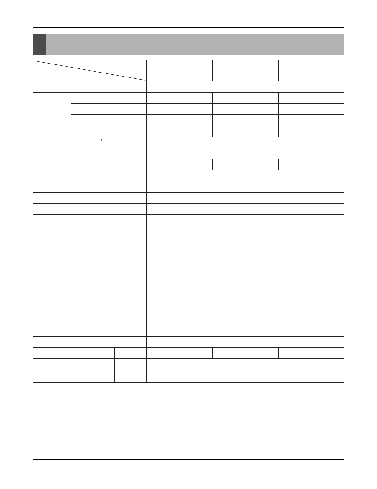
Specfications
Product Specifications
POWER SUPPLY
CAPACITY
POWER SUPPLYPOWER SUPPLY
(BTU/h)CAPACITYCAPACITY
INPUT
(BTU/h)(BTU/h)
POWER SUPPLY
(W)INPUTINPUT
CAPACITY
COOLING
(W)(W)
(BTU/h)
RUNNING CURRENT
COOLINGCOOLING
INPUT
(A)RUNNING CURRENTRUNNING CURRENT
(W)
E.E.R
(A)(A)
COOLING
(BTU/W.h)E.E.RE.E.R
RUNNING CURRENT
INDOOR (
(BTU/W.h)(BTU/W.h)
(A)
C)INDOOR (INDOOR (
E.E.R
OUTDOOR (
C)C)
(BTU/W.h)
C)OUTDOOR (OUTDOOR (
INDOOR (
REFRIGERANT (R-22) CHARGE
C)C)
C)
EVAPORATOR
REFRIGERANT (R-22) CHARGEREFRIGERANT (R-22) CHARGE
OUTDOOR (
CONDENSER
EVAPORATOREVAPORATOR
C)
FAN, INDOOR
CONDENSERCONDENSER
REFRIGERANT (R-22) CHARGE
FAN, OUTDOOR
FAN, INDOORFAN, INDOOR
EVAPORATOR
FAN SPEEDS, FAN/COOLING/HEATING
FAN, OUTDOORFAN, OUTDOOR
CONDENSER
FAN MOTOR
FAN SPEEDS, FAN/COOLING/HEATINGFAN SPEEDS, FAN/COOLING/HEATING
FAN, INDOOR
OPERATION CONTROL
FAN MOTORFAN MOTOR
FAN, OUTDOOR
ROOM TEMP. CONTROL
OPERATION CONTROLOPERATION CONTROL
FAN SPEEDS, FAN/COOLING/HEATING
AIR DIRECTION CONTROL
ROOM TEMP. CONTROLROOM TEMP. CONTROL
FAN MOTOR
CONSTRUCTION
AIR DIRECTION CONTROLAIR DIRECTION CONTROL
OPERATION CONTROL
PROTECTOR
CONSTRUCTIONCONSTRUCTION
ROOM TEMP. CONTROL
COMPRESSOR
PROTECTORPROTECTOR
AIR DIRECTION CONTROL
FAN MOTOR
COMPRESSORCOMPRESSOR
CONSTRUCTION
POWER CORD
FAN MOTORFAN MOTOR
PROTECTOR
DRAIN SYSTEM
POWER CORDPOWER CORD
COMPRESSOR
NET WEIGHT
DRAIN SYSTEMDRAIN SYSTEM
FAN MOTOR
(lbs/kg)NET WEIGHTNET WEIGHT
POWER CORD
OUTSIDE DIMENSION (inch)
(lbs/kg)(lbs/kg)
DRAIN SYSTEM
(W x
OUTSIDE DIMENSION (inch)OUTSIDE DIMENSION (inch)
NET WEIGHT
H(W x(W x
(lbs/kg)
xHH
OUTSIDE DIMENSION (inch)
D) x x(W x (mm)D) D) H (mm)(mm) x
1ø, 115V, 60Hz
D)
8,000
1ø, 115V, 60Hz1ø, 115V, 60Hz
(mm)
8,0008,0008,000 10,0008,0008,000
1ø, 115V, 60Hz
820
10,00010,0008,000
740820820
8,000
1,020740740
10,000
7.3
1,0201,020820
7.07.37.3
740
9.47.07.0
1,020
9.8
9.49.47.3
10.89.89.8
7.0
9.810.810.8
9.4
26.7(DB)* 19.4(WB)**
9.89.89.8
35(DB)* 23.9(WB)**
26.7(DB)* 19.4(WB)**26.7(DB)* 19.4(WB)**
10.8
420g(14.8 oz)
35(DB)* 23.9(WB)**35(DB)* 23.9(WB)**
9.8
410g(14.3 oz)420g(14.8 oz)420g(14.8 oz)
26.7(DB)* 19.4(WB)**
480g(16.9 oz)410g(14.3 oz)410g(14.3 oz)
35(DB)* 23.9(WB)**
2 ROW 11 STACKS, LOUVER-FIN TYPE
480g(16.9 oz)480g(16.9 oz)420g(14.8 oz)
2 ROW 15 STACKS, STRAGHT TYPE
2 ROW 11 STACKS, LOUVER-FIN TYPE2 ROW 11 STACKS, LOUVER-FIN TYPE
410g(14.3 oz)
TURBO FAN
2 ROW 15 STACKS, STRAGHT TYPE2 ROW 15 STACKS, STRAGHT TYPE
480g(16.9 oz)
PROPELLER TYPE FAN WITH SLINGER RING
TURBO FANTURBO FAN
2 ROW 11 STACKS, LOUVER-FIN TYPE
3/3
PROPELLER TYPE FAN WITH SLINGER RINGPROPELLER TYPE FAN WITH SLINGER RING
2 ROW 15 STACKS, STRAGHT TYPE
6 POLES
3/33/3
TURBO FAN
REMOTE CONTROLLER
6 POLES6 POLES
PROPELLER TYPE FAN WITH SLINGER RING
THERMISTOR
REMOTE CONTROLLERREMOTE CONTROLLER
3/3
VERTICAL LOUVER (RIGHT & LEFT)
THERMISTORTHERMISTOR
6 POLES
HORIZONTAL LOUVER (UP & DOWN)
VERTICAL LOUVER (RIGHT & LEFT)VERTICAL LOUVER (RIGHT & LEFT)
REMOTE CONTROLLER
TOP DOWN CHASSIS
HORIZONTAL LOUVER (UP & DOWN)HORIZONTAL LOUVER (UP & DOWN)
THERMISTOR
OVERLOAD PROTECTOR
TOP DOWN CHASSISTOP DOWN CHASSIS
VERTICAL LOUVER (RIGHT & LEFT)
INTERNAL THERMAL PROTECTOR
OVERLOAD PROTECTOROVERLOAD PROTECTOR
HORIZONTAL LOUVER (UP & DOWN)
3 WIRE WITH GROUDING
INTERNAL THERMAL PROTECTORINTERNAL THERMAL PROTECTOR
TOP DOWN CHASSIS
ATTACHMENT PLUG (CORD-CONNECTED TYPE)
3 WIRE WITH GROUDING3 WIRE WITH GROUDING
OVERLOAD PROTECTOR
DRAIN PIPE OR SPLASHED BY FAN SLINGER
ATTACHMENT PLUG (CORD-CONNECTED TYPE)ATTACHMENT PLUG (CORD-CONNECTED TYPE)
INTERNAL THERMAL PROTECTOR
62/28
DRAIN PIPE OR SPLASHED BY FAN SLINGERDRAIN PIPE OR SPLASHED BY FAN SLINGER
3 WIRE WITH GROUDING
71/3262/2862/28
ATTACHMENT PLUG (CORD-CONNECTED TYPE)
62/28 71/3271/32
DRAIN PIPE OR SPLASHED BY FAN SLINGER
19
62/2862/28 62/28
9
19 19
71/32
/
99
62/28
16
//
19
x 12
1616
9 3
x 12x 12/ /
33
16 8
//x 12 x 19
88
3 3
x 19x 19/ /
33
8 8
//x 19
497 x 315 x 492
88
3
HBLG8004R(A4/B4)
L8004R(Y4)/M8004R(Y4)
497 x 315 x 492497 x 315 x 492
/
CL8000ER
8
HBLG1004R
L1004R/M1004R
CL8000ERCL8000ER
497 x 315 x 492
HBLG1004R
L1004R/M1004R
HBLG1004R
L1004R/M1004R
CL8000ER HBLG1004R
L1004R/M1004R
MODELS
ITEMS
MODELSMODELS
ITEMSITEMS
OPERATING
MODELS
CONDITION
OPERATINGOPERATING
ITEMS
* D
CONDITIONCONDITION
B* D* D
OPERATING
: dry bulbBB
CONDITION
** WB : wet bulb
: dry bulb : dry bulb* D
** WB : wet bulb** WB : wet bulb
B : dry bulb
** WB : wet bulb
Service Manual 7
8 Room Air Conditioner
Installation
Installation
Select the Best Location
Installation Check
How to Secure the Drain Pipe
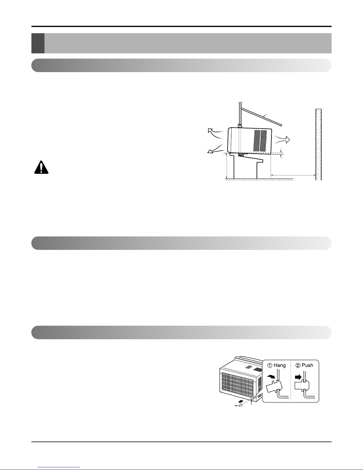
1. To prevent vibration and noise, make sure the unit is installed
securely and firmly.
2. Install the unit where the sun does not shine directly on the
unit.
3. The outside of the cabinet must extend outward for at least
12" and there should be no obstacles, such as a fence or
wall, within 20" from the back of the cabinet because it will
prevent heat radiation of the condenser.
Restriction of outside air will greatly reduce the cooling efficiency of the air conditioner.
CAUTION: All side louvers of the cabinet must
remain exposed on the outdside of the structure.
4. Install the unit slanted slightly so the back is slightly lower
than the front (about 1/
4"). This will force condensed water
to the outside.
5. Install the unit with the bottom about 30"~60" above the
floor level.
The setting conditions must be checked prior to initial starting.
The following items are especially important checking points when the installation is finished.
1. Grounding wire (Green or Green and Yellow) is provided in the power cord. The green wire must be grounded.
2. Connect to a single-outlet 15A circuit.
(or 20A circuit for Electric Heater Model)
3. To avoid vibration or noise, make sure the air conditioner is installed securely.
4 Avoid placing furniture or draperies in front of the air inlet and outlet.
In humid weather, excess water may cause the Base Pan to
overflow. To drain the water, remove the Drain Cap and secure
the Drain Pipe to the rear hole of the Base Pan. (Figure. 2)
Figure 2
ABOUT / "
Over 20"
HEAT
RADIATION
FENCE
AWNING
OUTSIDE
INSIDE
COOLED AIR
30"-60"
1
4
Figure 1
Drain Pipe
Drain Cap
Service Manual 9
Installation
How to Install
Window Requirements
All supporting parts should be secured to
firm wood, masonry, or metal.
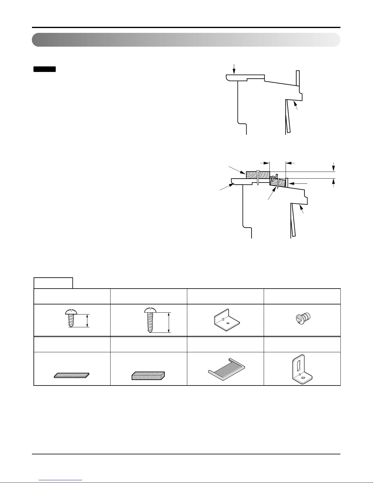
1. This unit is designed for installation in standard double
hung windows with actual opening widths of 22" to 36".
The upper and lower sash must open sufficiently to allow
a clear vertical opening of 13" from the bottom of the
sash to the window stool.
2. If storm window presents interference, fasten a 2" wide
wood strip to the inner window sill across the full width of
the sill. The wood strip should be thick enough to raise
the height of the window sill so that the unit can be
installed without interference by the storm window
frame. See Figure. 4. Top of wood strip should be
approximately 3/4" higher than the storm window frame
(STORM WINDOW FRAME) or wood strip (OUTDOORS) to help condensation to drain properly to the
outside.
3.
Install a second wood strip (approximately 6" long by 11/2"
wide and same thickness as first strip) in the center of the
outer sill flush against the back off the inner sill. This will
raise the L bracket as shown Figure. 4.
4. If the distance between STORM WINDOW FRAME and
WOOD STRIP MOUNTED ON TOP OF INNER SILL is
more than 1", two of wood strip are not necessary.
Installation
NOTICE
OUTDOORSINDOORS
INNER
SILL
OUTER
SILL
INNER
SILL
WOOD STRIP MOUNTED
ON TOP OF INNER SILL
WOOD STRIP
FOR
L
BRACKET
3/4"
CLEARANCE
1" MAX.
STORM
WINDOW
FRAME
OUTDOORSINDOORS
OUTER
SILL
Figure 3
Figure 4
HARDWARE
TYPE E: 1EA
(SASH SEAL)
(Not adhesive backed)
TYPE D: 1EA
(SEAL STRIP)
(Adhesive backed)
TYPE F: 2EA
(GUIDE PANEL)
TYPE C: 3EA
(L BACKET)
TYPE A: 11EA
(SHORT SCREW)
10mm
TYPE B: 5EA
(WOOD SCREW)
16mm
TYPE G: 1EA
(SUPPORT BACKET)
DRAIN PIPE
10 Room Air Conditioner
Installation
BEFORE INSTALLATION
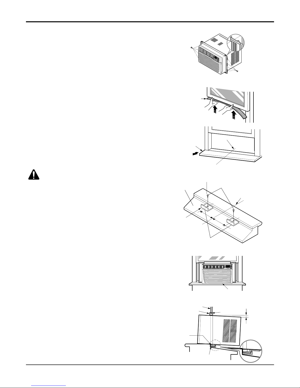
1. Insert the guide panels into the guides of the air conditioner.
Fasten the curtains to the unit with screws (TYPE A) as
shown Figure. 5.
2.
Cut the adhesive-backed seal strip (TYPE D) to the window
width.
Remove the backing from the seal strip and attach the seal
strip to the underside of the bottom window. (
Figure
. 6)
NOW START INSTALLATION
1. LOCATING UNIT IN WINDOW
Open the window and mark center line on the center of the
inner sill, as shown in Figure. 6.
2. ATTACH L BRACKET
a. Install the L brackets behind the inner window sill, with
the short side of bracket as shown.
Use the 2 screws (TYPE A) provided.
b. The bracket helps to hold unit securely in place. Be sure
to place bracket edge flush against back of inner sill. See
Figure. 7.
CAUTION:
During the following step, hold
unit firmly until window sash is lowered to top
channel behind side panel frames. Personal injury or
property damage may result if unit falls from window.
3. INSTALL THE AIR CONDITIONER IN THE WINDOW
a. Carefully lift the air conditioner and slide it into the open
window. Make sure the bottom guide of the air conditioner drops into the notches of the
L bracket. See Figure. 8.
IMPORTANT :
When the air conditioner drops into the L bracket, the air con-
ditioner will be centered in window opening as shown in
Figure. 9.
b. While steadying the air conditioner, carefully bring the
window sash down behind the upper guide of the air conditioner, as shown in Figure. 10.
ROOM SIDE
CENTER LINE
INNER SILL
SEAL STRIP
(TYPE D)
OUTSIDE
INSIDE
L
BRACKET
OUTER SILL
SHORT SIDE
INNER SILL
TYPE A
8"
8"
CENTER LINE
SEAL
WINDOW FRAME
BOTTOM
GUIDE
ABOUT
1/4"
L
BRACKET
UPPER GUIDE
Figure 5
Figure 6
Figure 7
Figure 8
Figure 9
Figure 10
Type A
Type A
C enter L ine
F
TEMP
F1 LOW
F2 MED
F3 HIGH
Dry Timer
Fan
Energy
Saver
Cool

Service Manual 11
Installation
4. SECURE THE GUIDE PANELS
Extend the guide panels (TYPE F) to fill the window
opening using 4 screws (TYPE B) to secure them, as
shown in Figure. 11.
5. INSTALL THE SASH SEAL AND SASH LOCK
a. Cut the sash seal (TYPE E) to the window width. Stuff
the sash seal between the glass and the window to
prevent air and insects from getting into the room, as
shown in Figure. 11.
b. Fasten the L bracket using a (TYPE A) screw, as
shown in Figure. 11.
6. Window installation of room air conditioner is now
completed. See ELECTRICAL DATA for attaching
power cord to electrical outlet.
REMOVAL FROM WINDOW
Trun the air conditioner off, disconnect the
power cord, remove the L bracket and the
screws installed through the top and bottom
of the guide panels, and save for reinstallation later. Close the guide panels. keeping a
firm grip on the air conditioner, raise the
sash, and carefully tilt the air conditioner
backward, draining any condensate water.
Lift the air conditioner from the window ad
remove the sash seal from between the windows.
NOTICE
Figure 11
Type B
Sash Seal
(Type F)
L Bracket
Type A
12 Room Air Conditioner
Operation
Operation
• Designed for COOLING ONLY.
• Powerful and quiet cooling.
• Top-down chassis for the simple installation and service.
• Low air-intake, top cooled-air discharge.
• Built-in adjustable Thermistor
• Washable one-touch filter
• Compact size
• Equipped with reliable and efficient rotary
compressor.
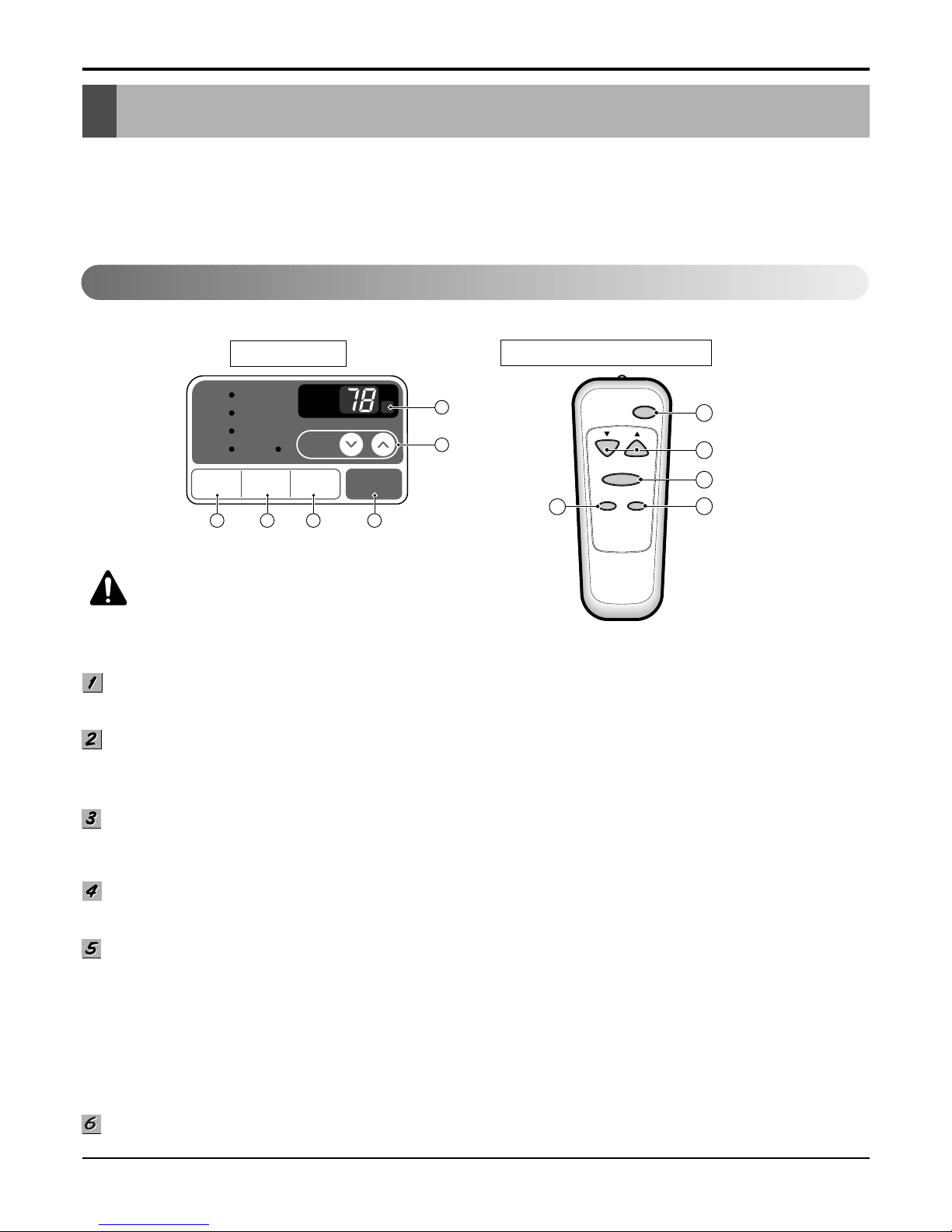
REMOTE CONTROL
DISPLAY
'
F
TIMER POWERMODE
TEMP
FAN
SPEED
F1 LOW
F2 MED
F3 HIGH
Dry Timer
Fan
Energy
Saver
Cool
Power
Temp
Fan Speed
Timer Mode
1
2
3
4
5
1
2
6
3 45
PRECAUTION:
The Remote Control unit will not
function properly if strong light strikes the sensor window
of the air conditioner or if there are obstacles between the
Remote Control unit and the air conditioner.
POWER BUTTON
To turn the air conditioner ON, push the button. To turn the air conditioner OFF, push the button again.
This button takes priority over any other buttons.
ROOM TEMPERATURE SETTING BUTTON
This button can automatically control the temperature of the room. The temperature can be set within a range of 60°F to
86°F by 1°F. (16°C to 30°C by 1°C)
Select the lower number for lower temperature of the room.
OPERATION MODE SELECTION BUTTON
Every time you push this button, it will shift among COOL, ENERGY SAVER, FAN and DRY.
-
Energy Saver: If Energy Save mode is selected, the fan stops when the compressor stops cooling.a
Approximately every 3 minutes the fan will turn on and check the room air to determine if cooling is needed.
FAN SPEED SELECTOR
Every time you push this button, it is set as follows.
(Hi [F3] ➔ Low [F1] ➔ Med [F2] ➔ Hi [F3] ➔ Low [F1] ➔...)
ON/OFF TIMER BUTTON
You can set the time when the unit will turn on or turn off automatically by pressing the timer button. If the unit is operating,
this button controls the time it will be turned off. If the unit is off state, this button controls the time it will start. Every time
you push this button, the remaining time will be set as follows.
- Stopping operation
(1Hour ➔ 2Hours ➔ 3Hours ➔ 4Hours ➔ 5Hours ➔ 6Hours ➔ 7Hours ➔ 8Hours ➔ 9Hours ➔ 10Hours ➔ 11Hours ➔
12Hours ➔ 0Hour ➔ 1Hour ➔ 2Hours ➔... )
- Starting operation
(1Hour ➔ 2Hours ➔ 3Hours ➔ 4Hours ➔ 5Hours ➔ 6Hours ➔ 7Hours ➔ 8Hours ➔ 9Hours ➔ 10Hours ➔ 11Hours ➔
12Hours ➔ off ➔ 1Hour ➔ 2Hours ➔ ... )
REMOCON SIGNAL RECEIVER
Function of Controls
 Loading...