

LG HBLG7000H Service Manual

Room Air Conditioner
SERVICE MANUAL
CAUTION
-BEFORE SERVICING THE UNIT, READ THE SAFETY
PRECAUTIONS IN THIS MANUAL.
-ONLY FOR AUTHORIZED SERVICE PERSONNEL.
MODEL: HBLG7000H
website http://biz.LGservice.com
e-mail http://www.LGEservice.com/techsup.html

—2—
1. PREFACE
1.1 SAFETY PRECAUTIONS................................2
1.2 INSULATION RESISTANCE TEST.................2
1.3 SPECIFICATIONS...........................................3
1.4 FEATURES......................................................4
2.
DISASSEMBLY INSTRUCTIONS
2.1 MECHANICAL PARTS....................................5
2.1.1 FRONT GRILLE .....................................5
2.1.2 CABINET................................................5
2.1.3 CONTROL BOX .....................................5
2.2 AIR HANDLING PARTS..................................6
2.2.1 AIR GUIDE AND BLOWER....................6
2.2.2 FAN AND SHROUD...............................6
2.3 ELECTRICAL PARTS......................................7
2.3.1 OVERLOAD PROTECTOR....................7
2.3.2 COMPRESSOR......................................7
2.3.3 CAPACITOR...........................................7
2.3.4 POWER CORD ......................................8
2.3.5 THERMOSTAT.......................................8
2.3.6 ROTARY SWITCH .................................8
2.3.7 MOTOR ..................................................8
2.4 REFRIGERATION CYCLE..............................9
2.4.1 CONDENSER.........................................9
2.4.2 EVAPORATOR.......................................9
2.4.3 CAPILLARY TUBE.................................9
3.
INSTALLATION
3.1 SELECT THE BEST LOCATION...................12
3.2 CHECK OF INSTALLATION..........................12
3.3 HOW TO DRAIN............................................12
3.4 HOW TO INSTALL ........................................13
3.5
HOW TO USE THE REVERSIBLE INLET GRILLE
...17
4.
TROUBLESHOOTING GUIDE
4.1 OUTSIDE DIMENSIONS...............................18
4.2 PIPING SYSTEM...........................................18
4.3 TROUBLESHOOTING GUIDE......................19
5. CIRCUIT DIAGRAM...............................24
6. EXPLODED VIEW..................................25
7. REPLACEMENT PARTS LIST........26
1. PREFACE
This
SERVICE MANUAL provides various service information, including the mechanical and electrical
parts etc. This room air conditioner was manufactured and assembled under a strict quality control system.
The refrigerant is charged at the factory. Be sure to read the safety precautions prior to servicing the unit.
1.1 SAFETY PRECAUTIONS
1. When servicing the unit, set the ROTARY SWITCH
or POWER SWITCH to OFF and unplug the power
cord.
2. Observe the original lead dress.
If a short circuit is found, replace all parts which
have been overheated or damaged by the short
circuit.
3. After servicing the unit, make an insulation resistance test to protect the customer from being
exposed to shock hazards.
1.2
INSULATION RESISTANCE TEST
1.Unplug the power cord and connect a jumper
between 2 pins (black and white).
2. The grounding conductor (green or green & yellow)
is to be open.
3. Measure the resistance value with an ohm meter
between the jumpered lead and each exposed
metallic part on the equipment at all the positions
(except OFF or O) of the ROTARY SWITCH.
4. The value should be over 1MΩ.
CONTENTS

—3—
1.3 SPECIFICATIONS
POWER SUPPLY
CAPACITY (Btu/h)
INPUT (W)
RUNNING CURRENT
(A)
E.E.R. (Btu/W.h)
CAPACITY (Btu/h)
INPUT (W)
RUNNING CURRENT
(A)
INDOOR (°C)
OUTDOOR (°C)
INDOOR (°C)
OUTDOOR (°C)
REFRIGERANT (R-22) CHARGE(g)
EVAPORATOR
CONDENSER
FAN, INDOOR
FAN, OUTDOOR
FAN SPEEDS (FAN/COOLING/HEATING)
FAN MOTOR
OPERATION CONTROL
ROOM TEMP. CONTROL
CONSTRUCTION
ELECTRIC HEATER
COMPRESSOR
FAN MOTOR
ELECTRIC HEATER
DRAIN SYSTEM
NET WEIGHT (lbs/kg)
OUTSIDE DIMENSION (inch)
(W x H x D) (mm)
1Ø, 115V, 60Hz
7,000
720
6.6
9.7
3,850
1,260
11.0
26.7 (DB) 19.4 (WB)
35 (DB) 23.9 (WB)
21.1 (DB) 15.6 (WB)
8.3 (DB) 6.1 (WB)
330 (11.6 OZ)
2 ROW 16 STACKS
2 ROW 16 STACKS
BLOWER
PROPELLER TYPE FAN WITH SLINGER-RING
1/ 2/ 2
4 POLES
ROTARY SWITCH
THERMOSTAT
VERTICAL LOUVER (RIGHT & LEFT)
HORIZONTAL LOUVER (UP & DOWN)
SLIDE IN-OUT CHASSIS
1.2 KW, 115V
OVERLOAD PROTECTOR
INTERANL THERMAL PROTECTOR
FUSE LINK, BIMETAL THERMOSTAT
1.6m (3 WIRE WITH GROUDING)
ATTACHMENT PLUG (CORD-CONNECTED TYPE)
DRAIN PIPE OR SPLASHED BY FAN SLINGER
64/29
18
1
/2 x137/8 x2011/16
470 x 353 x 525
MODEL
ITEMS
OPERATING
TEMPERATURE
AIR DIRECTION CONTROL
POWER CORD
PROTECTOR
HEATING
COOLING
COOLING
HEATING
HBLG7000H
—4—
1.4 FEATURES
• Powerful and quiet cooling.
• Slide-in and slide-out chassis for the simple installation
and service.
• Reversible inlet grille.
• Side air-intake, side cooled-air discharge.
• Built in adjustable THERMOSTAT.
• Washable one-touch filter.
• Compact size.
•CAUTION
When the air conditioner has been performing its
cooling operation and is turned off or set to the fan
position, wait at least 3 minutes before resetting to
the cooling operation again.
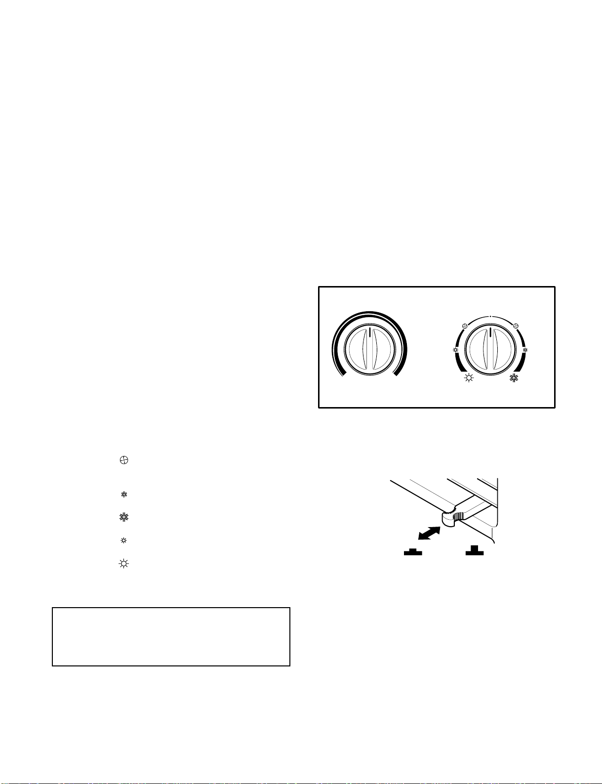
• THERMOSTAT
Turn the thermostat control to the desired setting. The
centrol position is a normal setting for average
conditions. You can change this setting, if necessary,
in accordance with your temperature preference.
The thermostat automatically controls cooling or
heating, but the fan runs continuously whenever the air
conditioner is in operation. If the room is too warm,
turn the thermostat control clockwise. If the room is too
cool, turn the themostat control anticlockwise.
• OPERATION
OFF ( ) :Turns the air conditioner off.
FAN ( ) : Permits the low fan speed
operation without cooling
(heating).
LOW COOL ( ) : Permits cooling with the low fan
speed operation.
HIGH COOL( ) : Permits cooling with the high fan
speed operation.
LOW HEAT ( ) : Permits heating with the low fan
speed operation.
HIGH HEAT ( ) : Permits heating with the high fan
speed operation.
• VENTILATION
The ventilation lever must be in the CLOSE position in
order to maintain the best cooling conditions.
When a fresh air is necessary in the room, set the
ventilation lever to the OPEN position.
The damper is opened and room air is exhausted.
o
Thermostat
Operation
Wait Three Minutes
Before Restarting
COOLERWARMER
O
VENTCLOSE OPEN
A slight heat odor may come from the unit when
first switching to HEAT after the cooling season is
over. This odor, caused by fine dust particles on
the heater, will disappear quickly.

—5—
2.1 MECHANICAL PARTS
2.1.1 FRONT GRILLE
1. Open the lnlet grille upward or downward.
2. Remove the screw which fastens the front grille.
3. Pull the front grille from the right side.
4. Remove the front grille.
5. Re-install the component by referring to the
removal procedure, above.(See Figure 1)
2.1.2 CABINET
1. After disassembling the FRONT GRILLE, remove
the 2 screws which fasten the cabinet at both
sides.
2. Remove the 2 screws which fasten the cabinet at
back.
3. Pull the base pan forward. (See Figure 2)
4. Remove the cabinet.
5. Re-install the component by referring to the
removal procedure, above.
2.1.3 CONTROL BOX
1. Disconnect the unit from the power source.
2. Remove the front grille. (Refer to section 2.1.1)
3. Remove the cabinet. (Refer to section 2.1.2)
4. Remove the screw which fastens the control box
cover.
5. Remove the housing which connects motor wire
in the control box.
6. Remove the 3 leads from the compressor.
(Refer to section 2.3.1)
7.Discharge the capacitor by placing a 20,000
ohmresistor across the capacitor terminals.
8. Remove the 2 screws which fasten the control
box.(See Figure 3)
9. Pull the control box forward completely.
10. Re-install the components by referring to the
removal procedure, above. (See Figure 3)
(Refer to the circuit diagram found on page 24 in
this manual or on the control box.)
T
h
e
r
m
o
s
t
a
t
O
p
e
r
a
t
i
o
n
W
a
i
t
T
h
r
e
e
M
in
u
te
s
B
e
f
o
re
R
e
s
t
a
r
tin
g
C
O
O
L
E
R
W
A
R
M
E
R
O
Therm
ostat
Operation
W
a
it T
h
re
e
M
in
u
t
e
s
B
e
fo
r
e
R
e
s
ta
rtin
g
C
O
O
L
E
R
W
A
R
M
E
R
O
T
he
r
m
o
st
at
Op
er
a
tio
n
W
a
i
t
T
h
r
e
e
M
i
n
u
t
e
s
B
e
f
o
r
e
R
e
s
t
a
r
t
i
n
g
C
OO
L
E
R
W
AR
M
E
R
O
T
h
e
rm
o
s
ta
t
O
p
e
ra
t
io
n
W
a
i
t
T
h
r
e
e
M
i
n
u
t
e
s
B
e
f
o
r
e
R
e
s
t
a
r
t
i
n
g
C
O
O
L
E
RW
A
R
M
E
R
O
2. DISASSEMBLY INSTRUCTIONS
— Before the following disassembly, POWER SWITCH set to OFF and disconnect the power cord.
Figure 1
Figure 3
Figure 2
—6—
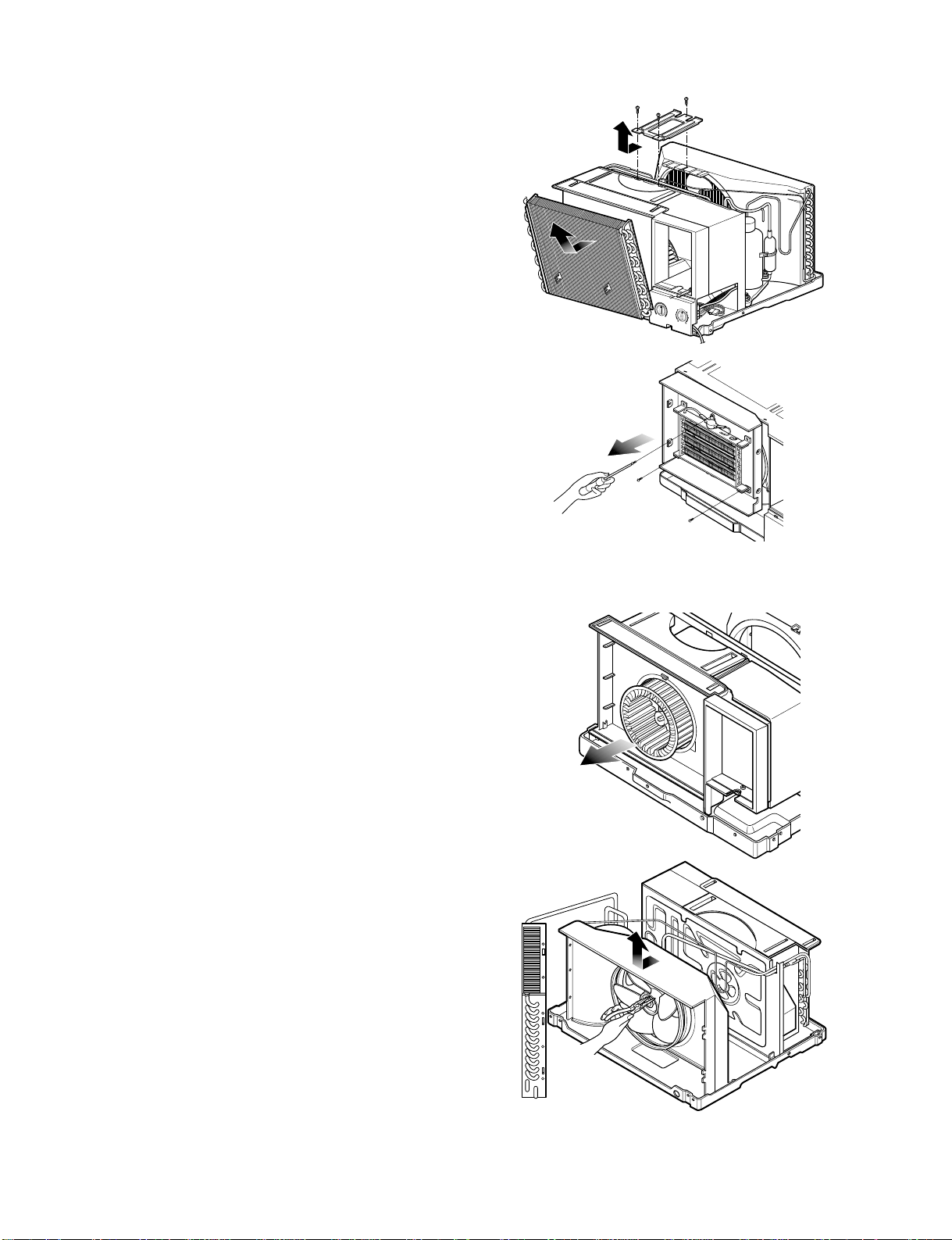
2.2 AIR HANDLING PARTS
2.2.1 AIR GUIDE AND BLOWER
1. Remove the front grille. (Refer to section 2.1.1)
2. Remove the cabinet. (Refer to section 2.1.2)
3. Remove the control box. (Refer to section 2.1.3)
4. Remove the 3 screws which fasten the brace.
5. Remove the brace.
6. Remove the 2 screws which fasten the evaporator.
7. Move the evaporator forward and pulling it upward
slightly. (See Figure 4)
8. Move the evaporator to the left carefully.
9. Remove the 3 screws which fasten the Heater
Cover.(See Figure 5)
10. Remove the Heater Cover.
11.Remove the clamp with a hand plier which
secures the blower.(Sww Figure 6)
12. Remove the blower.
13. Remove the 4 screws which fasten the air guide
from the barrier.
14. Move the air guide backward, pulling out from the
base pan.
15. Re-install the components by referring to the
removal procedure, above.
2.2.2 FAN AND SHROUD
1. Remove the cabinet. (Refer to section 2.1.2)
2. Remove the brace (Refer to section 2.2.1)
3. Remove the 3 screws which fasten the condenser.
4. Move the condenser to the left carefully.
5. Remove the clamp which secures the fan.
6. Remove the fan and then pull out the shroud.
(See Figure 7)
7. Re-install by referring to the removal procedure.
T
h
e
r
m
o
s
t
a
t
O
p
e
r
a
t
i
o
n
W
a
it
Th
re
e
M
in
ut
e
s
B
e
fo
re
R
e
st
art
in
g
C
O
O
L
E
R
W
A
R
M
E
R
O
Figure 4
Figure 5
Figure 6
Figure 7
—7—
2.3 ELECTRICAL PARTS
2.3.1 OVERLOAD PROTECTOR
1. Remove the cabinet. (Refer to section 2.1.2)
2. Remove the nut which fastens the terminal cover.
3. Remove the terminal cover. (See Figure 8)
4. Remove all the leads from the overload protector.
5. Remove the overload protector.
6. Re-install the component by referring to the
removal procedure, above.
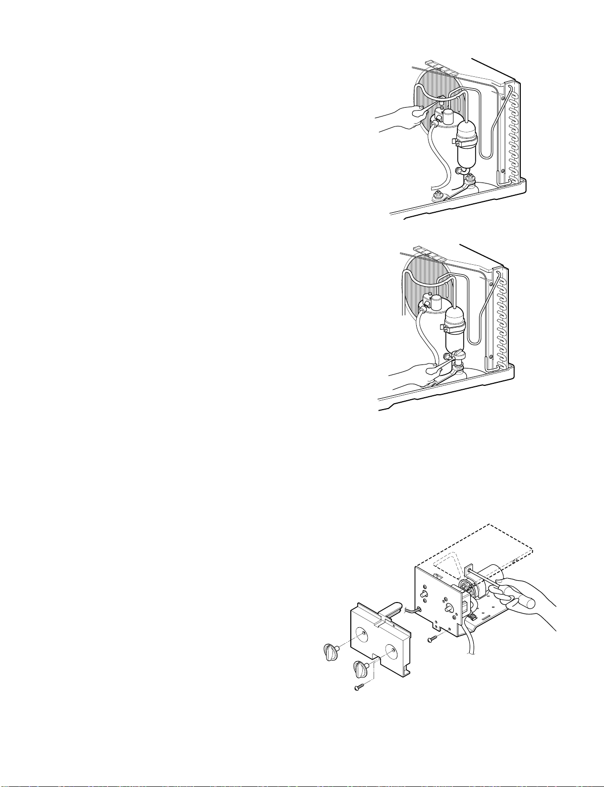
2.3.2 COMPRESSOR
1. Remove the cabinet. (Refer to section 2.1.2)
2. Discharge the refrigerant system using a Freon
TM
Recovery System.
If there is no valve to attach the recovery system,
install one (such as a WATCO A-1) before venting
the FreonTM. Leave the valve in place after
servicing the system.
3. Remove the overload protector. (Refer to section
2.3.1)
4. After purging the unit completely, unbraze the
suction and discharge tubes at the compressor
connections.
5. Remove the 3 nuts and the 3 washers which
fasten the compressor.
6. Remove the compressor. (See Figure 9)
7. Re-install the components by referring to the
removal procedure, above.
2.3.3 CAPACITOR
1. Remove the control box. (Refer to section 2.1.3)
2. Remove the knobs and the screw which fasten
control panel from control box.
3. Remove the screw which located in the front.
4. Open the bottom side of control box.
5. Remove the screw and the clamp which fastens
the capacitor.
6. Disconnect all the leads of capacitor terminals.
7. Re-install the components by referring to the
removal procedure, above. (See Figure 10)
Figure 8
Figure 9
Figure 10

—8—
2.3.4 POWER CORD
1. Remove the control box. (Refer to section 2.1.3)
2. Open the control box. (Refer to section 2.3.3)
3. Disconnect the grounding screw from the control
box.
4. Disconnect the 2 receptacles.
5. Remove a screw which fastens the clip cord.
(See Figure 11)
6. Remove the power cord.
7. Re-install the component by referring to the above
removal procedure, above.
(Use only one ground-marked hole for ground
connection.)
8. If the supply cord of this appliance is damaged, it
must be replaced by the special cord. (The
special cord means the cord which has the same
specification marked on the supply cord attached at
the unit.)
2.3.5 THERMOSTAT
1. Remove the control box. (Refer to section 2.1.3)
2. Open the control box. (Refer to section 2.3.3)
3. Remove the 2 screws which fasten the thermostat.
4. Disconnect 2 leads of thermostat terminals.
5. Remove the thermostat.
6. Re-install the components by refereing to the above
removal procedure. (See Figure 12)
2.3.6 ROTARY SWITCH
1. Remove the control box. (Refer to section 2.1.3)
2. Open the control box. (Refer to section 2.3.3)
3. Remove the 2 screws which fasten the rotary switch.
4. Disconnect all the leads of the rotary switch terminals.
5. Remove the rotary switch.
6. Re-install the components by referring to the above
removal procedure. (See Figure 13)
2.3.7 MOTOR
1. Remove the cabinet. (Refer to section 2.1.2)
2. Remove the evaporator. (Refer to section 2.2.1)
3. Remove the orifice. (Refer to section 2.2.1)
4. Remove the blower. (Refer to section 2.2.1)
5. Remove the fan. (Refer to section 2.2.2)
6. Remove the control box cover and housing of the
motor in the control box. (Refer to section 2.1.3)
7. Remove the 2 screws which fasten the motor from
the mount motor. (See Figure 14)
8. Remove the motor.
9. Re-install the components by referring to the
removal procedure, above.(See Figure 14)
Figure 13
Figure 12
Figure 11
Figure 14

—9—
2.4 REFRIGERATING CYCLE
2.4.1 CONDENSER
1. Remove the cabinet. (Refer to section 2.1.2)
2. Remove the 3 screws which fasten the
brace.(Refer to section 2.2.1)
3. Remove the 3 screws which fasten the condenser
and shroud.
4. After discharging the refrigerant completely,
unbraze the interconnecting tube at the condenser
connections.
5. Remove the condenser carefully.
6. Re-install the component by referring to notes.
(See Figure 15)
2.4.2 EVAPORATOR
1. Remove the cabinet. (Refer to section 2.1.2)
2. Remove the 2 screws which fasten the evaporator.
3. Move the evaporator sideways carefully.
(Refer to section 2.2.1)
4. After discharging the refrigerant completely,
unbraze the interconnecting tube at the evaporator
connections.
5. Remove the evaporator carefully.
6. Re-install the component by referring to notes.
(See Figure 16)
2.4.3 CAPILLARY TUBE
1. Remove the cabinet. (Refer to section 2.1.2)
2. After discharging the refrigerant completely,
unbraze the interconnecting tube at the capillary
tube.(See caution above)
3. Remove the capillary tube.
4. Re-install the component by referring to notes.
Figure 15
Figure 16
Discharge the refrigerant system using a
FreonTMRecovery System.
If there is no valve to attach the recovery
system, install one (such as a WATCO A-1)
before venting the FreonTM. Leave the valve in
place after servicing the system.
CAUTION
 Loading...