

Page 1
+
COLOR MONIT OR
SER VICE MANUAL
CHASSIS NO. : CL-1 1
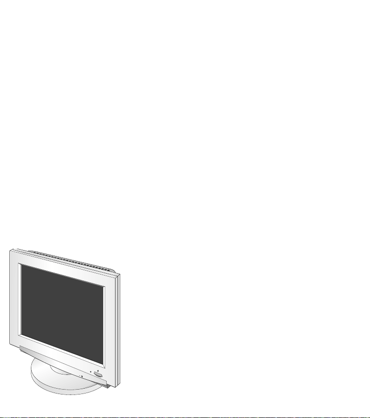
MODEL: FPD1800, LG881Y
CAUTION
BEFORE SERVICING THE UNIT,
READ THE SAFETY PRECAUTIONS IN THIS MANUAL.
Page 2
1. LCD CHARACTERISTICS
Type : Color Active Matrix TFT LCD
Size : 18.1inch (45.97cm)
Pixel Pitch : 0.2805mm(H) x 0.2805mm(V)
Pixel Format : 1280 x 1024 pixels
RGB Stripe Arrangement
Color Depth : 8-bit, color (24 bits)
Active Video Area : 359mm x 287mm
Surface Treatment : Anti-Glare, Hard Coating (3H)
Backlight Unit : CCFL (Cold Cathode
Fluorescent Lamp)
Electrical Interface : DVI-D
2. OPTICAL CHARACTERISTICS
2-1. Viewing Angle by Contrast Ratio
≥
10
Left : 80°
Right : 80°
Top : 80°
Bottom : 80°
2-2. Luminance : 200 min.(Center of screen)
2-3. Contrast Ratio : 200 min : 1
3. SIGNAL (Refer to the Timing Chart)
3-1. Type : TMDS Digital
3-2. Voltage Level : 3.3V
3-3. Input Impedance : 50Ω
3-4. Operating Frequency
Horizontal : 64 kHz
Vertical : 60 Hz
4. POWER SUPPLY
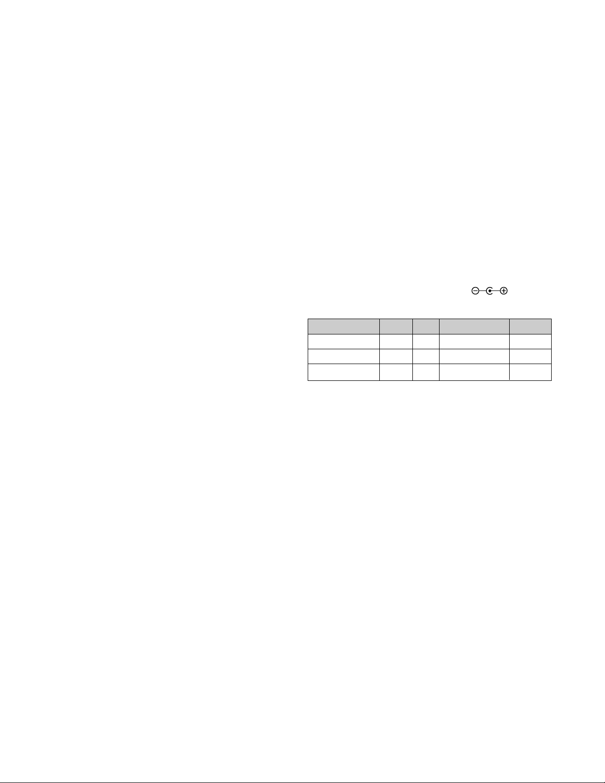
4-1. Power Adaptor
Input : AC 90~264V, 50/60Hz 1.4~0.7A
Output : DC 12V 5.8A
4-2. Power Consumption
5. ENVIRONMENT
5-1. Operating Temperature: 10°C ~ 35°C (50°F ~ 95°F)
(Ambient)
5-2. Relative Humidity : 5% ~ 90%
(Non-condensing)
5-3. Altitude : 0~10,000 feet
6. DIMENSIONS (with TILT/SWIVEL)
Width : 434.0mm (17.09'')
Depth : 235.0mm (9.25'')
Height : 443.1mm (17.44'')
7. WEIGHT (with TILT/SWIVEL)
Net Weight : 9.0kg (19.84 lbs)
Gross Weight : 12.3kg (27.12 lbs)
CONTENTS
- 2 -
SPECIFICATIONS ................................................... 2
PRECAUTION ......................................................... 3
TIMING CHART ....................................................... 4
OPERATING INSTRUCTIONS ................................ 4
WIRING DIAGRAM ................................................. 5
DISASSEMBLY ....................................................... 6
BLOCK DIAGRAM ................................................... 8
DESCRIPTION OF BLOCK DIAGRAM.....................9
ADJUSTMENT ...................................................... 10
TROUBLESHOOTING GUIDE .............................. 11
PRINTED CIRCUIT BOARD................................... 13
EXPLODED VIEW...................................................14
REPLACEMENT PARTS LIST ............................... 16
PIN CONFIGURATION........................................... 20
SCHEMATIC DIAGRAM......................................... 28
PACKING AND ACCESSORIES ............................ 34
SPECIFICATIONS
MODE
POWER ON (NORMAL)
DPM
POWER OFF
SIGNAL
ON
OFF
-
POWER CONSUMPTION
less than 50W
less than 5 W
less than 5 W
LED COLOR
GREEN
ORANGE
OFF
VIDEO
ACTIVE
OFF
-
Page 3
PRECAUTION
- 3 -
WARNING FOR THE SAFETY-RELATED COMPONENT.
• There are some special components used in LCD
monitor that are important for safety. These parts are
marked on the schematic diagram and the
replacement parts list. It is essential that these critical
parts should be replaced with the manufacturer’s
specified parts to prevent electric shock, fire or other
hazard.
• Do not modify original design without obtaining written
permission from Gateway or you will void the original
parts and labor guarantee.
TAKE CARE DURING HANDLING THE LCD MODULE
WITH BACKLIGHT UNIT.
• Must mount the module using mounting holes arranged
in four corners.
• Do not press on the panel, edge of the frame strongly
or electric shock as this will result in damage to the
screen.
• Do not scratch or press on the panel with any sharp
objects, such as pencil or pen as this may result in
damage to the panel.
• Protect the module from the ESD as it may damage the
electronic circuit (C-MOS).
• Make certain that treatment person’s body are
grounded through wrist band.
• Do not leave the module in high temperature and in
areas of high humidity for a long time.
• The module not be exposed to the direct sunlight.
• Avoid contact with water as it may a short circuit within
the module.
• If the surface of panel become dirty, please wipe it off
with a softmaterial. (Cleaning with a dirty or rough cloth
may damage the panel.)
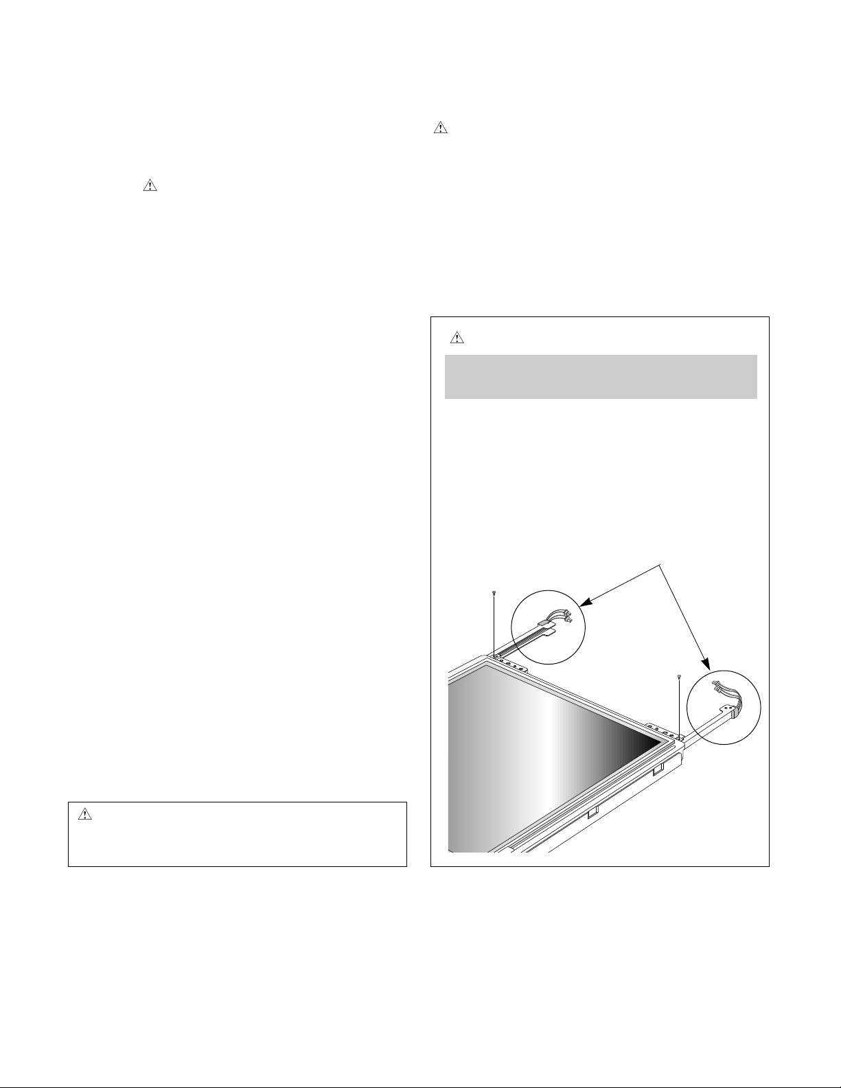
WARNING
BE CAREFUL ELECTRIC SHOCK !
• If you want to replace with the new backlight (CCFL) or
inverter circuit, must turn off the power button or
disconnect the AC adapter because high voltage
appears at inverter circuit about 650Vrms.
• Handle with care wires or connectors of the inverter
circuit. If the wires are pressed cause short and may
burn or take fire.
CAUTION
Please use only a plastic screwdriver to protect yourself
from shock hazard during service operation.
CAUTION
• There is two backlight, and be careful of treatment it.
• MTBF (Mean Time Between Failure) of a backlight
is about 30,000 hours(mininum 20,000 hours).
Backlight Ass’y
(P/N: 6913TZZ002A)
IF BRIGHTNESS OF THE LCD MODULE DARKEN,
REPLACE THE BACKLIGHT ONE OR ALL.
Page 4
TIMING CHART
- 4 -
MODE
1
H
(Pixels)
V
(Lines)
Sync
Polarity
+
+
Dot Clock
108.0MHz
1280
X
1024
63.981KHz
60.02Hz
1688
1066
1280 48
1024 1
112408
42 3
248
38
Frequency
Total
Period
(A)
Video
Active
Time
(B)
Blanking
Time
(C)
Sync
Duration
(E)
Back
Porch
(F)
Front
Porch
(D)
Resolution
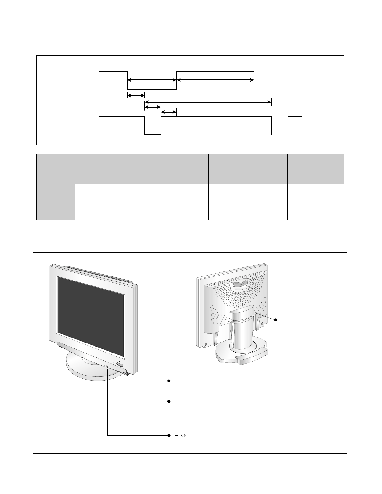
OPERATING INSTRUCTIONS
Power ON/OFF Button
This button is used to turn the monitor on and off.
Power Indicator
This indicator lights up green when the monitor operates
normally; in DPMS (Energy Saving) mode, power off mode-its
color changes to orange.
Brightness Control Buttons
Use these buttons for adjusting the brightness.
+
+
Front View
Rear View
DVI-D Signal Connectors
VIDEO
C
D
F
SYNC
E
B
A
Page 5
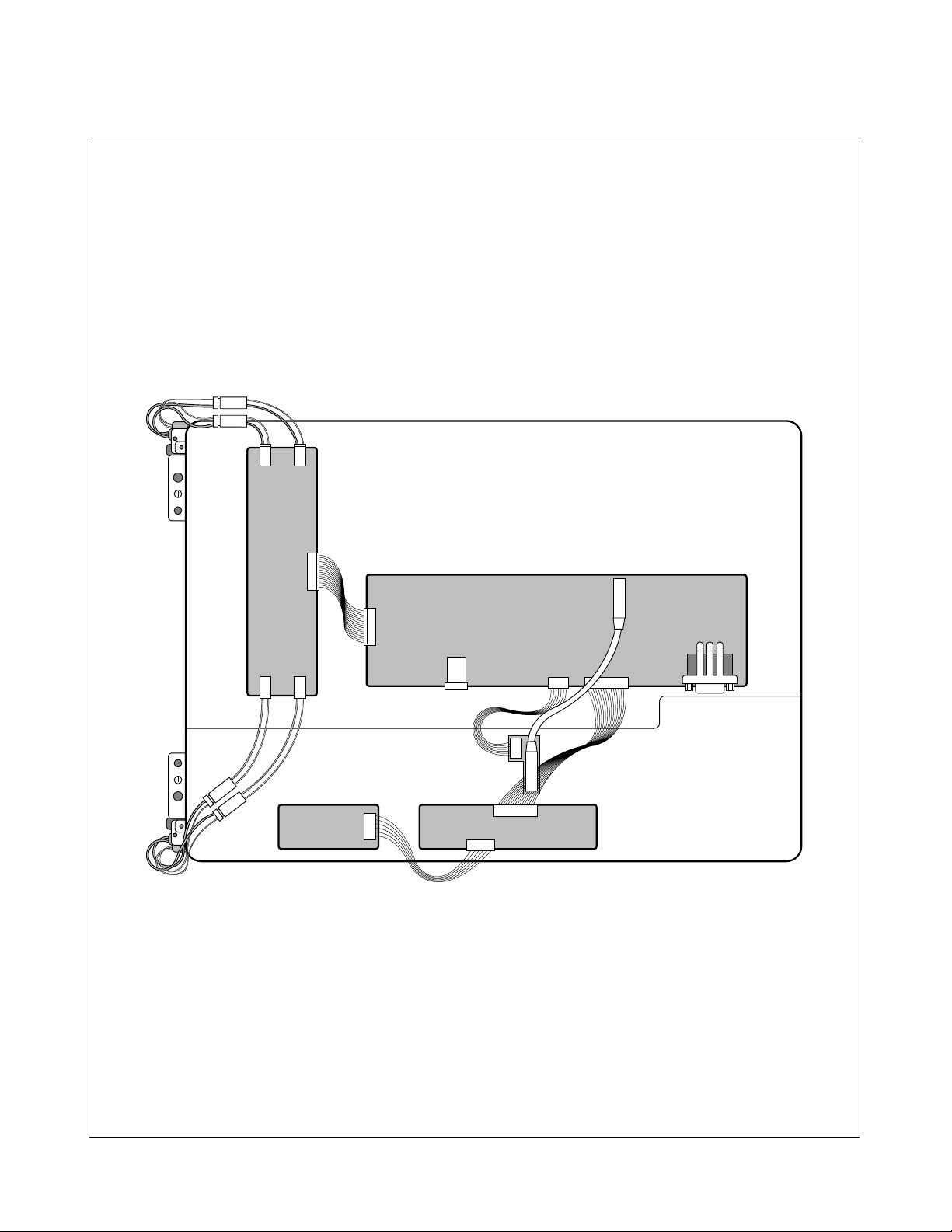
WIRING DIAGRAM
- 5 -
J3
J4
CN2CN3
CN5
CN4
J5
CN2
J5
J6
J3
CN1
J2
J1
Page 6
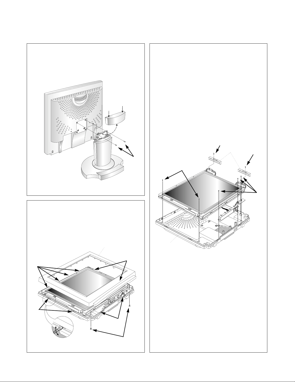
DISASSEMBLY
- 6 -
(a)
1. TILT/SWIVEL REMOVAL
1) Remove Hinge Cover.
(Push the tilt cover both side).
2) Remove two screws (a).
3) Remove the Tilt/swivel.
2. FRONT CABINET REMOVAL
1) Remove two screws (a).
2) Release ten latches (b).
3) Remove the Front Cabinet.
3. INVERTER WIRE SHIELD & BACK COVER
REMOVAL
1) Remove four screws (a).
2) Remove two Inverter Wire Shield.
3) Remove three screws (b).
4) Remove the Back Cover.
(a)
(b)
(a)
(a)
(b)
(b)
(b)
(b)
(a)
Front Cabinet
Back Cover
Inverter Wire
Shield
Page 7
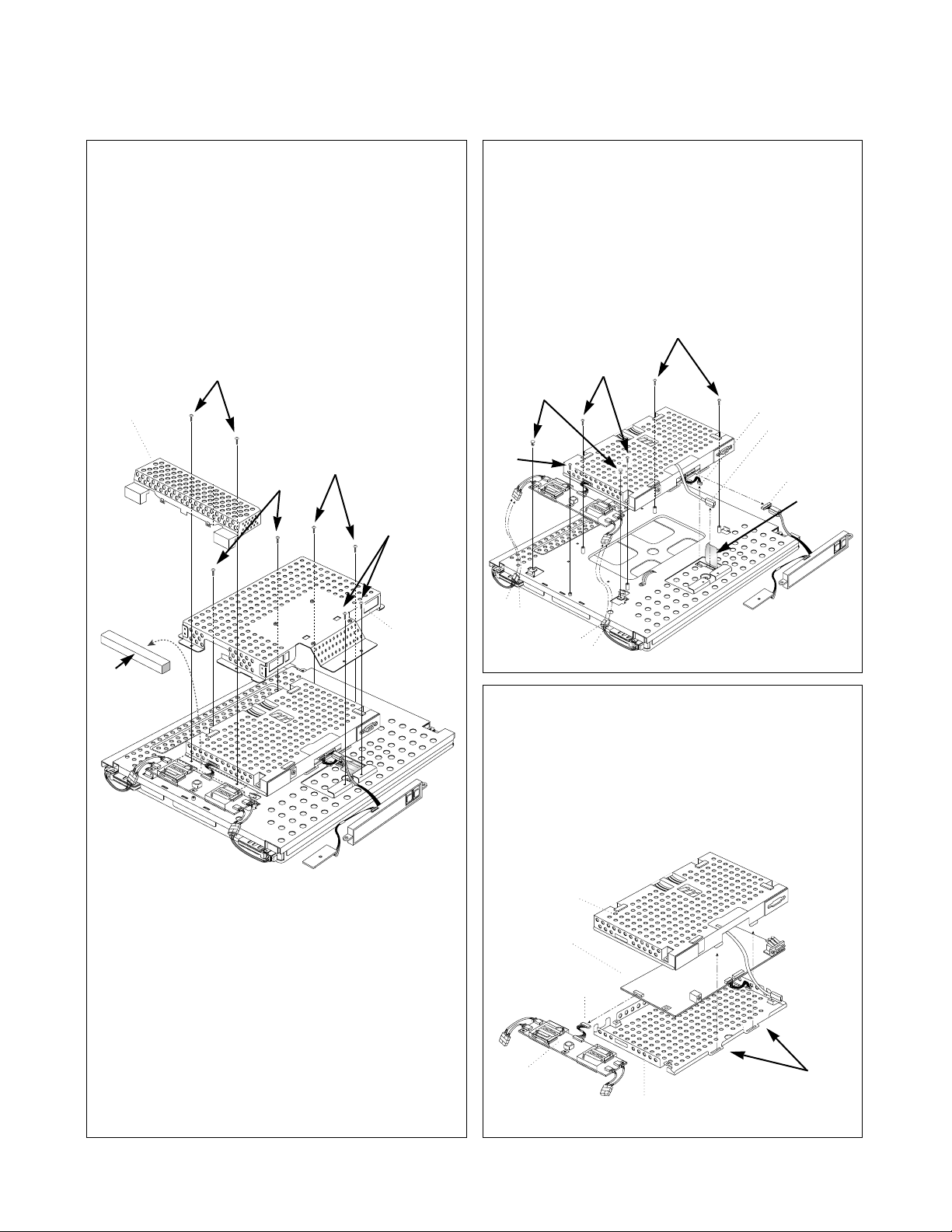
- 7 -
4. INVERTER FRAME & REAR SHIELD REMOVAL
1) Remove sponge (a).
2) Remove two screws (b).
3) Remove the Inverter Frame.
4) Remove six screws (c).
5) Remove the Rear Frame.
(a)
(a)
(a)
(b)
(c)
5. MAIN TOTAL ASS’Y REMOVAL
1) Disconnect J1, J2, J3 and J4.
2) Remove five screws (a).
3) Remove two fixers (b).
4) Remove Aluminium Tape (c).
5) Disconnect FPC Cable, Module Connector and
Control PCB Connector.
6) Remove Main Total Ass’y and Inverter PCB
Ass’y.
6. MAIN PCB SHIELD REMOVAL
1) Disconnect J04.
2) Remove Inverter Ass’y from the Main PCB.
3) Release two latches (a).
4) Divide Top Shield, Main PCB, and Bottom Shield.
(b)
Rear Frame
Inverter Frame
FPC Cable
Control PCB Connector
Module Connector
PCB Shield
(Top)
Inverter Ass’y
Main PCB
J04
PCB Shield (Bottom)
(c)
(c)
(c)
(a)
J1
J2
J3
J4
(a)
Page 8
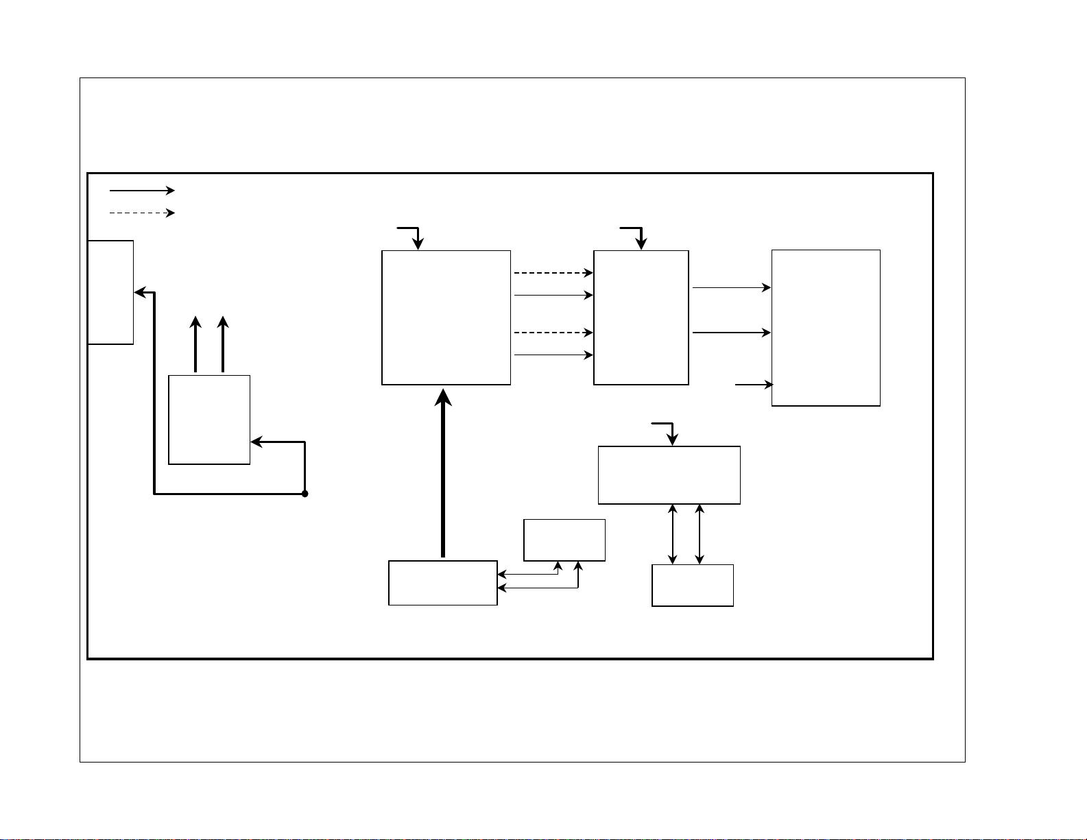
BLOCK DIAGRAM
- 8 -
SiI161
Display
Data
Transmitter
LCD
Module
Form PSU
12V
DC/DC
Converter
Inverter
Data
Clock
Micro-Controller
12V
LVDS83
LG LCD PANEL
( LM181E3 )
. Brightness
3.3 V 3.3 V
5 V
MC68HC08
12V
5 V
3.3 V
LVDS Even
LVDS Odd
TMDS
Input Port
DVI-D
EEPROM
For
EDID
SDL-H
SDA-H
EEPROM
SDL SDA
Page 9

DESCRIPTION OF BLOCK DIAGRAM
- 9 -
1. DC/DC Converter
This circuit supplies stand-by 5V(+5Vst) and regular 5V(+5V) for using LM2674 and LM2596S from AC/DC adapter
(+12V). The +5V voltage supply to 3.3V voltage regulator.
2. Micro-Controller
This circuit consists of one EEPROM IC(24C02) which stores the control data for system and communicates
DDC(Display Data Channel) and oscillator(X2).
The operating procedures of Micro-Controller and its associated circuit are as follows;
1) The system controller detects frequency of vertical sync from Sil161A(U1) 47pin through AHC86(U10).
The controller controls the power switching IC (SI4925) by the detection of vertical sync(H/V Sync).
2) The Micro-Controller controls the brightness of inverter by using the key control button and store the data to
EEPROM (24C02).
3. LVDS Circuit
LVDS transmitter (U2, U3) delivers digital signal to the receiver of module by the voltage swing of 1V.
The peripheral circuitry of transmitter gets the DHS, DVS, DEN, DISPCLK signal, output LVDS signal.
At the power down mode, MICOM lets the power down signal be low and shutdown pin be active low.
4. T.M.D.S Receiver
The Sil161A gets the T.M.D.S. video signal converted T.M.D.S. to 2 channel TTL level. The output 8-bit
R, G, B, DHS, DVS and DE signal to the transmitter(U2, U3).
Page 10
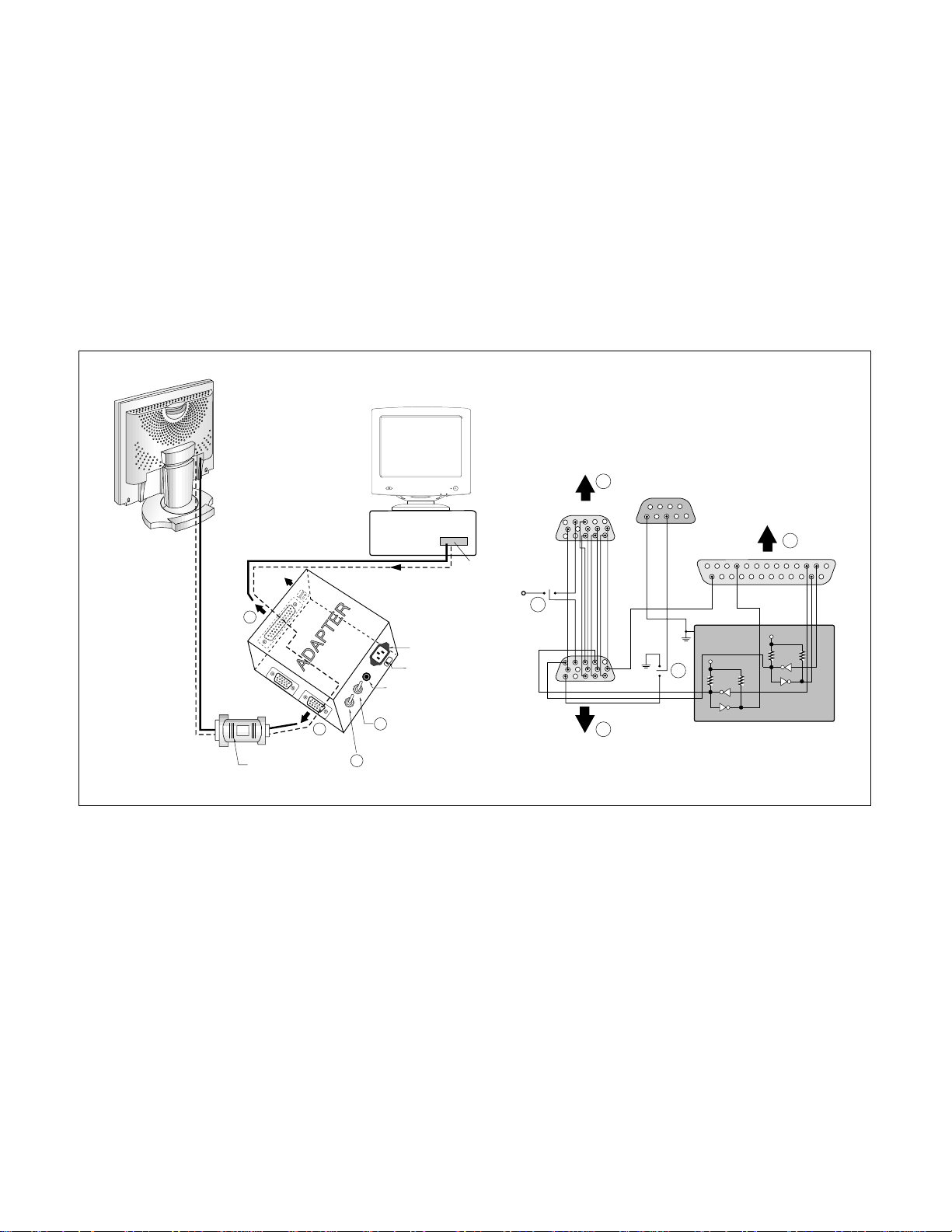
ADJUSTMENT
- 10 -
220
IBM
Compatible PC
PARALLEL PORT
Power inlet (required)
Power LED
ST Switch
Power Select Switch
(110V/220V)
Control Line
Not used
RS232C
PARALLEL
V-SYNC
POWER
ST
VGS
MONITOR
E
E
V-Sync On/Off Switch
(Switch must be ON.)
F
F
A
B
B
C
C
15
10
5
5
69
1
1
1
14
13
25
6
5V
5V
5V
4.7K
4.7K
4.7K
74LS06
74LS06
OFF ON
OFF
ON
11
DVI-D Connector
Figure 1. Cable Connection
All adjustment are thoroughly checked and corrected
when the monitor leaves the factory, but sometimes
several minor adjustment may be required.
• Alignment appliances and tools.
- IBM compatible PC.
- Alignment Adapter and Software.
- DVI-D Connector.
- Install the cable for adjustment such as Figure 1and run
the alignment program on the DOS for IBM compatible PC.
1. DDC Data Write Procedure
1) Use this procedure only when there is some problem
on 24LC02(DDC support IC).
2) Select EEPROM -> Write EDID command and
Enter.
3) This will write the EDID data to 24LC02.
Page 11
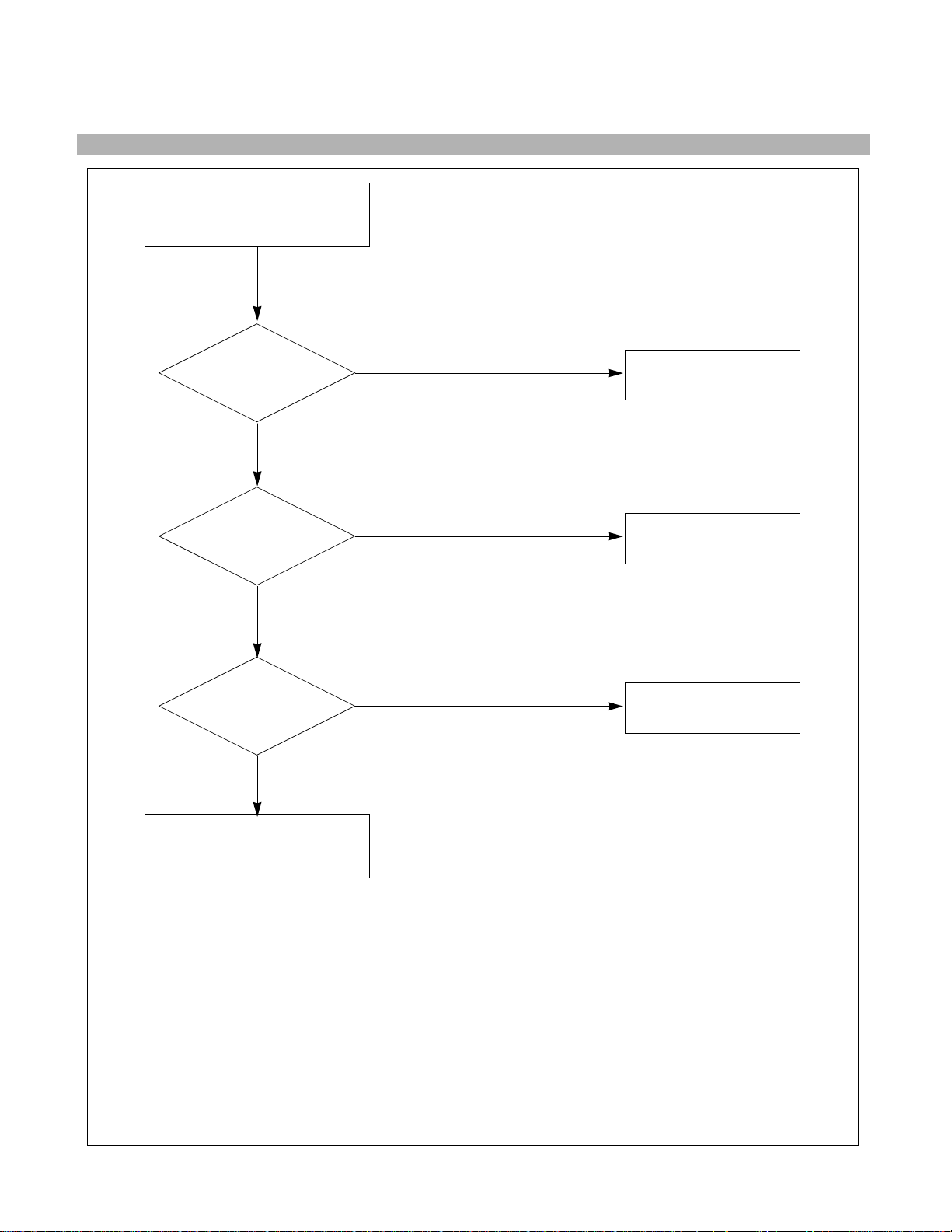
TROUBLESHOOTING GUIDE
- 11 -
TROUBLE IN
U8, U5
CHECK
5VST VOLTAGE
(5V) ?
NO
1. NO POWER
NO POWER
(POWER INDICATOR OFF
)
TROUBLE
SOMEWHERE ELSE
TROUBLE IN
ADAPTOR
CHECK J7
INPUT VOLTAGE
(12V) ?
NO
TROUBLE IN
U4, U6
CHECK
+3.3V VOLTAGE ?
NO
YES
YES
YES
Page 12

- 12 -
2. NO RASTER
TROUBLE IN
U1
CHECK
U11 PIN 42
(H. PULSE)
NO
NO VIDEO
TROUBLE IN
U12
CHECK
U12 PIN 5
(12V-MOD) ?
NO
TROUBLE IN
U1
CHECK
U11 PIN 1
V. PULSE ?
NO
TROUBLE IN
U6
CHECK
U6 PIN 2
(3.3V)?
NO
YES
YES
YES
YES
TROUBLE IN
LCD MODULE
Page 13

PRINTED CIRCUIT BOARD
- 13 -
1. MAIN BOARD (Component Side) 2. CONTROL BOARD (Component Side)
R87
R8
R9
R14
R11
R23
R12
ZD3
C20
R3
C21
R24
C22
C23
C25
ZD10
D9
D10
ZD4
C19
R22
R6
C31
C29
L202
D7
D8
C24
C28
D1
D3
D4
U1
C27
L201
D2
J2
C18
C14
C13
C11
C15
C17
C16
C12
C10
BA12BA13BA10BA11BA8 BA9 BA1
BA7
BA2 BA3 BA4 BA5 BA6
CA9 CA10
CA7 CA8 CA11 CA12 CA5 CA1CA6 CA2 CA3 CA4
R20
C46
C45
R17
C38
C40
C39
R19
R21
C47
C44
U3
R18
R16
C48
C41
C49
C42
C43
U2
C78
C79
C80
C81
C82
J3
C77
C74
C75
C76
C73
R75
J6
R76
R77
R78
Q2Q3
U10
C67
C26
D5
C94
J5
R47
R50
R33
U9
R25
R46
U13
C52
R30
D6
R36
R37
C65
C60
C61
R39
R66
R34
U11
R67
C68 R26
R31
C85
C86
C87
C89
C63
C51
R55
R56
R38
R53
R54
C69
X2
R7
C64
R57
R59
R60
R58
C72
C70
R62
C84
C83
R35
C62
R71
R48
C71
R13
R64
R63
R61
L5
C5
U7
R28
R41
R70
R89
R65
R88
C36
U12
R29
R27
R40
R42
R43
R51
R52
R32
C53
R74
C54
R1
Q1
R45
R44
R10
R15
C30
C35
U5
C37
U6
C3
C2
C1
J7
L2
C34
C8
ZD6
C50
C32
C33
C9
C105
R5
U8
R2
R4
U4
L24
L27
C107
C106
C6
C7
L1
R79
C103
C101
C91
C4
C90
C93
ZD5
C97
C98
C99
C100
C102
L6
C95
C96
C92
L13
J4
30
20110
PN:6870T247A11
LGE DIGITAL MONITOR
SIH 2000.03.08
40
80
90
50
60
70
SOLDERING DIRECTION
SW5
PN:6870T247C11 VER 1.1
LG MNT
PWR Board
LED1
1
J8
SW1
R3
SW2
R4
J1
1
R1
R2
R5
SW3
ZD2
ZD1
1
J7
SW4
LG MNT
PN:6870T247C11
Key Board
VER : 1.2
Page 14

EXPLODED VIEW
- 14 -
2
3
4
5
6
7
8
9
10
12
a
b
c
c
c
c
c
d
e
5-1
5-2
5-3
11
1
a
d
Page 15

EXPLODED VIEW PARTS LIST
- 15 -
Ref. No.
1
2
3
4
5
5-1
5-2
5-3
6
7
8
9
10
11
12
a
b
c
d
e
Part No.
3091TKL010A
6304TLT181N
4814TKK064A
4951TKS034B
3313TL8006A
4950TKK049B
6871TMT158A
4950TKK048J
6633TZA004A
4814TKK067A
4950TKS097A
6871TST156A
3809TKL006D
3550TKK053F
3043TKK037F
332-095E
4930TKK014A
332-110A
332-095C
332-105F
Description
CABINET ASS’Y
LCD MODULE, LGE TFT LCD LM181E3-A2 18.1”
INVERTER WIRE SHIELD
METAL ASS’Y, MAIN FRAME
MAIN TOTAL ASS’Y
PCB SHIELD (BOTTOM)
MAIN PCB ASS’Y
PCB SHIELD (TOP)
INVERTER ASS’Y
INVERTER SHIELD
METAL, REAR FRAME
KEY CONTROL PCB ASS’Y
BACK COVER ASS’Y
HINGE COVER
TILT SWIVEL ASS’Y
SCREW, PZP+3x16 (MSWR/FZMW)
HOLDER, FIXER
SCREW, PZS+3x6 (MSWR/FZMY)
SCREW, PZP+3x12 (MSWR/FZMY)
SCREW, PVS+4x10 (MSWR/FZMW)
Q'ty
1
1
2
1
1
1
1
1
1
1
1
1
1
1
1
4
2
13
5
2
Material
PC+ABS
SPTE
SPTE
SPTE
SPTE
SBHG1
PC+ABS
PC+ABS
PC+ABS
STEEL
STEEL
STEEL
STEEL
Page 16

REPLACEMENT PARTS LIST
CAUTION: BEFORE REPLACING ANY OF THESE COMPONENTS,
READ CAREFULLY THE SAFETY PRECAUTIONS IN THIS MANUAL.
* NOTE : S SAFETY Mark
AL ALTERNATIVE PARTS
MODEL:FPD1800, LG881Y DATE: 2000. 4. 1.
*S *AL LOC. NO. PART NO. DESCRIPTION / SPECIFICATION REMARK
C1 0CH7476F661 CAPACITOR, CHIP[TANTALUM], 47UF 16V M 7343 TP(-)
C2 0CH3104K566 CAPACITOR, CHIP[CERAMIC LD-LESS HD], 0.1UF 50V K X 2012 R/TP
C3 0CH6102K406 CAPACITOR, CHIP[CERAMIC LD-LESS TC], 1000PF 50V J SL 2012 R/TP
C4 0CH3104K566 CAPACITOR, CHIP[CERAMIC LD-LESS HD], 0.1UF 50V K X 2012 R/TP
C5 0CH6102K406 CAPACITOR, CHIP[CERAMIC LD-LESS TC], 1000PF 50V J SL 2012 R/TP
C6 0CH8107J611 CAPACITOR, CHIP[AL. ELECTROLYTIC], 100UF 35V M 85STD(CYL) R/TP
C7 0CH8107J611 CAPACITOR, CHIP[AL. ELECTROLYTIC], 100UF 35V M 85STD(CYL) R/TP
C8 0CH3103K516 CAPACITOR, CHIP[CERAMIC LD-LESS HD], 10000PF 50V K B 2012 R/TP
C9 0CH7227D661 CAPACITOR, CHIP[TANTALUM], 220UF 10V M 7343 TP(-)
C10 0CH7106F621 CAPACITOR, CHIP[TANTALUM], 10UF 16V M 3528MM TP(-)
C11 0CH3104K566 CAPACITOR, CHIP[CERAMIC LD-LESS HD], 0.1UF 50V K X 2012 R/TP
C12 0CH3104K566 CAPACITOR, CHIP[CERAMIC LD-LESS HD], 0.1UF 50V K X 2012 R/TP
C13 0CH3104K566 CAPACITOR, CHIP[CERAMIC LD-LESS HD], 0.1UF 50V K X 2012 R/TP
C14 0CH3104K566 CAPACITOR, CHIP[CERAMIC LD-LESS HD], 0.1UF 50V K X 2012 R/TP
C15 0CH3104K566 CAPACITOR, CHIP[CERAMIC LD-LESS HD], 0.1UF 50V K X 2012 R/TP
C16 0CH3104K566 CAPACITOR, CHIP[CERAMIC LD-LESS HD], 0.1UF 50V K X 2012 R/TP
C17 0CH6102K406 CAPACITOR, CHIP[CERAMIC LD-LESS TC], 1000PF 50V J SL 2012 R/TP
C18 0CH3104K566 CAPACITOR, CHIP[CERAMIC LD-LESS HD], 0.1UF 50V K X 2012 R/TP
C19 0CH3104K566 CAPACITOR, CHIP[CERAMIC LD-LESS HD], 0.1UF 50V K X 2012 R/TP
C20 0CH3104K566 CAPACITOR, CHIP[CERAMIC LD-LESS HD], 0.1UF 50V K X 2012 R/TP
C21 0CH3104K566 CAPACITOR, CHIP[CERAMIC LD-LESS HD], 0.1UF 50V K X 2012 R/TP
C22 0CH3104K566 CAPACITOR, CHIP[CERAMIC LD-LESS HD], 0.1UF 50V K X 2012 R/TP
C24 0CH3104K566 CAPACITOR, CHIP[CERAMIC LD-LESS HD], 0.1UF 50V K X 2012 R/TP
C26 0CH3104K566 CAPACITOR, CHIP[CERAMIC LD-LESS HD], 0.1UF 50V K X 2012 R/TP
C27 0CH3104K566 CAPACITOR, CHIP[CERAMIC LD-LESS HD], 0.1UF 50V K X 2012 R/TP
C28 0CH3104K566 CAPACITOR, CHIP[CERAMIC LD-LESS HD], 0.1UF 50V K X 2012 R/TP
C29 0CH3104K566 CAPACITOR, CHIP[CERAMIC LD-LESS HD], 0.1UF 50V K X 2012 R/TP
C30 0CH7476F661 CAPACITOR, CHIP[TANTALUM], 47UF 16V M 7343 TP(-)
C31 0CH6102K406 CAPACITOR, CHIP[CERAMIC LD-LESS TC], 1000PF 50V J SL 2012 R/TP
C32 0CH3103K516 CAPACITOR, CHIP[CERAMIC LD-LESS HD], 10000PF 50V K B 2012 R/TP
C33 0CH3103K516 CAPACITOR, CHIP[CERAMIC LD-LESS HD], 10000PF 50V K B 2012 R/TP
C34 0CH7227D661 CAPACITOR, CHIP[TANTALUM], 220UF 10V M 7343 TP(-)
C35 0CH3103K516 CAPACITOR, CHIP[CERAMIC LD-LESS HD], 10000PF 50V K B 2012 R/TP
C36 0CE4776F618 CAPACITOR, AL.ELECTROLYTIC, 470U SMS 16V M FM5 TP5
C37 0CH3103K516 CAPACITOR, CHIP[CERAMIC LD-LESS HD], 10000PF 50V K B 2012 R/TP
C38 0CH3104K566 CAPACITOR, CHIP[CERAMIC LD-LESS HD], 0.1UF 50V K X 2012 R/TP
C39 0CH3104K566 CAPACITOR, CHIP[CERAMIC LD-LESS HD], 0.1UF 50V K X 2012 R/TP
C40 0CH3104K566 CAPACITOR, CHIP[CERAMIC LD-LESS HD], 0.1UF 50V K X 2012 R/TP
C41 0CH6560K416 CAPACITOR, CHIP[CERAMIC LD-LESS TC], 56PF 50V J NP0 2012 R/TP
C42 0CH3104K566 CAPACITOR, CHIP[CERAMIC LD-LESS HD], 0.1UF 50V K X 2012 R/TP
C43 0CH3104K566 CAPACITOR, CHIP[CERAMIC LD-LESS HD], 0.1UF 50V K X 2012 R/TP
C44 0CH3104K566 CAPACITOR, CHIP[CERAMIC LD-LESS HD], 0.1UF 50V K X 2012 R/TP
C45 0CH3104K566 CAPACITOR, CHIP[CERAMIC LD-LESS HD], 0.1UF 50V K X 2012 R/TP
C46 0CH3104K566 CAPACITOR, CHIP[CERAMIC LD-LESS HD], 0.1UF 50V K X 2012 R/TP
C47 0CH6560K416 CAPACITOR, CHIP[CERAMIC LD-LESS TC], 56PF 50V J NP0 2012 R/TP
C48 0CH3104K566 CAPACITOR, CHIP[CERAMIC LD-LESS HD], 0.1UF 50V K X 2012 R/TP
C49 0CH3104K566 CAPACITOR, CHIP[CERAMIC LD-LESS HD], 0.1UF 50V K X 2012 R/TP
C50 0CH7227D661 CAPACITOR, CHIP[TANTALUM], 220UF 10V M 7343 TP(-)
C51 0CH3104K566 CAPACITOR, CHIP[CERAMIC LD-LESS HD], 0.1UF 50V K X 2012 R/TP
C52 0CH3104K566 CAPACITOR, CHIP[CERAMIC LD-LESS HD], 0.1UF 50V K X 2012 R/TP
C53 0CH3104K566 CAPACITOR, CHIP[CERAMIC LD-LESS HD], 0.1UF 50V K X 2012 R/TP
C54 0CH3104K566 CAPACITOR, CHIP[CERAMIC LD-LESS HD], 0.1UF 50V K X 2012 R/TP
C60 0CH3104K566 CAPACITOR, CHIP[CERAMIC LD-LESS HD], 0.1UF 50V K X 2012 R/TP
C61 0CH3104K566 CAPACITOR, CHIP[CERAMIC LD-LESS HD], 0.1UF 50V K X 2012 R/TP
C62 0CH3104K566 CAPACITOR, CHIP[CERAMIC LD-LESS HD], 0.1UF 50V K X 2012 R/TP
C63 0CH6120K416 CAPACITOR, CHIP[CERAMIC LD-LESS TC], 12PF 50V J NP0 2012 R/TP
- 16 -
MAIN BOARD
CAPACITORs
Page 17

MODEL:FPD1800, LG881Y DATE: 2000. 4. 1.
*S *AL LOC. NO. PART NO. DESCRIPTION / SPECIFICATION REMARK
C64 0CH6120K416 CAPACITOR, CHIP[CERAMIC LD-LESS TC], 12PF 50V J NP0 2012 R/TP
C65 0CH6271K416 CAPACITOR, CHIP[CERAMIC LD-LESS TC], 270PF 50V J NP0 2012 R/TP
C67 0CH6101K416 CAPACITOR, CHIP[CERAMIC LD-LESS TC], 100PF 50V J NP0 2012 R/TP
C68 0CH6101K416 CAPACITOR, CHIP[CERAMIC LD-LESS TC], 100PF 50V J NP0 2012 R/TP
C69 0CH3103K516 CAPACITOR, CHIP[CERAMIC LD-LESS HD], 10000PF 50V K B 2012 R/TP
C70 0CH3103K516 CAPACITOR, CHIP[CERAMIC LD-LESS HD], 10000PF 50V K B 2012 R/TP
C71 0CH6101K416 CAPACITOR, CHIP[CERAMIC LD-LESS TC], 100PF 50V J NP0 2012 R/TP
C72 0CH6101K416 CAPACITOR, CHIP[CERAMIC LD-LESS TC], 100PF 50V J NP0 2012 R/TP
C83 0CH3104K566 CAPACITOR, CHIP[CERAMIC LD-LESS HD], 0.1UF 50V K X 2012 R/TP
C84 0CE4776F618 CAPACITOR, AL.ELECTROLYTIC, 470U SMS 16V M FM5 TP5
C85 0CH3104K566 CAPACITOR, CHIP[CERAMIC LD-LESS HD], 0.1UF 50V K X 2012 R/TP
C86 0CH3104K566 CAPACITOR, CHIP[CERAMIC LD-LESS HD], 0.1UF 50V K X 2012 R/TP
C87 0CH3104K566 CAPACITOR, CHIP[CERAMIC LD-LESS HD], 0.1UF 50V K X 2012 R/TP
C89 0CH3104K566 CAPACITOR, CHIP[CERAMIC LD-LESS HD], 0.1UF 50V K X 2012 R/TP
C90 0CH7106F621 CAPACITOR, CHIP[TANTALUM], 10UF 16V M 3528MM TP(-)
C91 0CH3103K516 CAPACITOR, CHIP[CERAMIC LD-LESS HD], 10000PF 50V K B 2012 R/TP
C92 0CH3103K516 CAPACITOR, CHIP[CERAMIC LD-LESS HD], 10000PF 50V K B 2012 R/TP
C93 0CH8107J611 CAPACITOR, CHIP[AL. ELECTROLYTIC], 100UF 35V M 85STD(CYL) R/TP
C94 0CH3104K566 CAPACITOR, CHIP[CERAMIC LD-LESS HD], 0.1UF 50V K X 2012 R/TP
C95 0CH3103K516 CAPACITOR, CHIP[CERAMIC LD-LESS HD], 10000PF 50V K B 2012 R/TP
C96 0CH3104K566 CAPACITOR, CHIP[CERAMIC LD-LESS HD], 0.1UF 50V K X 2012 R/TP
C97 0CH6221K416 CAPACITOR, CHIP[CERAMIC LD-LESS TC], 220PF 50V J NP0 2012 R/TP
C98 0CH6221K416 CAPACITOR, CHIP[CERAMIC LD-LESS TC], 220PF 50V J NP0 2012 R/TP
C99 0CH6221K416 CAPACITOR, CHIP[CERAMIC LD-LESS TC], 220PF 50V J NP0 2012 R/TP
C100 0CH6221K416 CAPACITOR, CHIP[CERAMIC LD-LESS TC], 220PF 50V J NP0 2012 R/TP
C101 0CH6221K416 CAPACITOR, CHIP[CERAMIC LD-LESS TC], 220PF 50V J NP0 2012 R/TP
C102 0CH6221K416 CAPACITOR, CHIP[CERAMIC LD-LESS TC], 220PF 50V J NP0 2012 R/TP
C103 0CH7106F621 CAPACITOR, CHIP[TANTALUM], 10UF 16V M 3528MM TP(-)
C106 0CH3104K566 CAPACITOR, CHIP[CERAMIC LD-LESS HD], 0.1UF 50V K X 2012 R/TP
C107 0CH3104K566 CAPACITOR, CHIP[CERAMIC LD-LESS HD], 0.1UF 50V K X 2012 R/TP
D1 0DS226009AA DIODE, SWITCHING, KDS226 TP KEC SOT-23 80V 300MA 2A 4NS 0.5UA
D2 0DS226009AA DIODE, SWITCHING, KDS226 TP KEC SOT-23 80V 300MA 2A 4NS 0.5UA
D3 0DS226009AA DIODE, SWITCHING, KDS226 TP KEC SOT-23 80V 300MA 2A 4NS 0.5UA
D4 0DS226009AA DIODE, SWITCHING, KDS226 TP KEC SOT-23 80V 300MA 2A 4NS 0.5UA
D5 0DS301109AA DIODE, SWITCHING, MMBD301LT1 TP MOTOROLA SOT23 30V 13NA 200NA
D6 0DS301109AA DIODE, SWITCHING, MMBD301LT1 TP MOTOROLA SOT23 30V 13NA 200NA
D7 0DS226009AA DIODE, SWITCHING, KDS226 TP KEC SOT-23 80V 300MA 2A 4NS 0.5UA
D8 0DS226009AA DIODE, SWITCHING, KDS226 TP KEC SOT-23 80V 300MA 2A 4NS 0.5UA
D9 0DS226009AA DIODE, SWITCHING, KDS226 TP KEC SOT-23 80V 300MA 2A 4NS 0.5UA
D10 0DS226009AA DIODE, SWITCHING, KDS226 TP KEC SOT-23 80V 300MA 2A 4NS 0.5UA
ZD3 0DZ560009DA DIODE, ZENER, UDZ S 5.6B TP ROHM-K SOD323 200MW 5.6V 5MA .PF
ZD4 0DZ560009DA DIODE, ZENER, UDZ S 5.6B TP ROHM-K SOD323 200MW 5.6V 5MA .PF
ZD5 0DR340009AA DIODE, RECTIFIER, MBRS340 TP FAIRCHILD NON 40V 3A 80A .SEC 2MA
ZD6 0DR190309AA DIODE, RECTIFIER, MBRS190T3 TP MOTOROLA 403A-03 90V 1A 50A 10NS
ZD10 0DZ560009DA DIODE, ZENER, UDZ S 5.6B TP ROHM-K SOD323 200MW 5.6V 5MA .PF
U1 0IS5161000A IC, SILICON IMAGE, SII161A 100PTQFP BK TMDS RECEIVER 165MHZ
U2 0ITI758300A IC, TEXAS INSTRUMENT, SN75LVDS83 56P,DDG TP 80MHZ F/LINK
U3 0ITI758300A IC, TEXAS INSTRUMENT, SN75LVDS83 56P,DDG TP 80MHZ F/LINK
U4 0INS259650A IC, NATIONAL SEMICONDUCTOR, LM2596-5V 5LEAD,TO263(S) TP 3A 5V
U5 0ISS780500H IC, SAMSUNG ELECTRONICS, KA78M05-R 3P,D-PAK TP 5V 0.5A REGUL
U6 0IRH033200A IC, ROHM, BA033FP-E2 MOLD-3 TP REGULATOR
U7 0IKE704200J IC, KEC, KIA7042AF SOT-89 TP 4.2V VOLTAGE DETECTOR
U8 0INS267450A IC, NATIONAL SEMICONDUCTOR, LM2674M-5.0 8SOP TP 0.5A 5V S/DOWN
U9 0ISS240210A IC, SAMSUNG ELECTRONICS, KS24C021CS SOP8 TP EEPROM 2K LOW VOL
U10 0ITI748600L IC, TEXAS INSTRUMENT, SN74AHC86D 14P,SOIC TP QUAD 2INPUT XOR
U11 0IZZTSZ069A IC[HYBRID ], 42PIN DIP BK LG881Y OPT ASSY
U12 0TF492509AA FET, SI4925DY TP TEMIC 30V 6.1A SO-8
U13 0ISS240210A IC, SAMSUNG ELECTRONICS, KS24C021CS SOP8 TP EEPROM 2K LOW VOL
- 17 -
DIODEs
ICs
Page 18

MODEL:FPD1800, LG881Y DATE: 2000. 4. 1.
*S *AL LOC. NO. PART NO. DESCRIPTION / SPECIFICATION REMARK
L1 6140TBZ007A COIL,CHOKE, DR10*7(K-30) 100UH 0.4MM 34.5T SMD CHOKE(LCD)
L2 6140TBZ016B COIL,CHOKE, DR10*7(YL-9N) 220UH 0.32MM 75T LI571D
L5 6210TCE001G CORE (CIRC), BEAD, HH-1M3216-501 CERATEC 3216MM R/TP
L6 6210TCE001G CORE (CIRC), BEAD, HH-1M3216-501 CERATEC 3216MM R/TP
L13 6210TCE001G CORE (CIRC), BEAD, HH-1M3216-501 CERATEC 3216MM R/TP
L24 6210TCE001G CORE (CIRC), BEAD, HH-1M3216-501 CERATEC 3216MM R/TP
L27 6210TCE001G CORE (CIRC), BEAD, HH-1M3216-501 CERATEC 3216MM R/TP
L201 6200TEZ007A FILTER(CIRC), CAPACITOR, STC-B SERIES(104B) NIIGATA(FILMAC)
L202 6200TEZ007A FILTER(CIRC), CAPACITOR, STC-B SERIES(104B) NIIGATA(FILMAC)
Q1 0TR162309CA TRANSISTOR, KSC1623 TP SAMSUNG SOT23 NPN EPI. SILICON TR
Q2 0TR162309CA TRANSISTOR, KSC1623 TP SAMSUNG SOT23 NPN EPI. SILICON TR
Q3 0TR162309CA TRANSISTOR, KSC1623 TP SAMSUNG SOT23 NPN EPI. SILICON TR
R1 0RH6802D622 RESISTOR, CHIP, 68K 1/10W 5 D.R/TP
R2 0RH2702D622 RESISTOR, CHIP, 27K 1/10W 5 D.R/TP
R3 0RH1002D622 RESISTOR, CHIP, 10K 1/10W 5 D.R/TP
R4 0RH4701D622 RESISTOR, CHIP, 4.7K 1/10W 5 D.R/TP
R5 0RH4701D622 RESISTOR, CHIP, 4.7K 1/10W 5 D.R/TP
R6 0RH5100D622 RESISTOR, CHIP, 510 1/10W 5 D.R/TP
R7 0RH1004D622 RESISTOR, CHIP, 1.0M 1/10W 5 D.R/TP
R8 0RH1002D622 RESISTOR, CHIP, 10K 1/10W 5 D.R/TP
R9 0RH1002D622 RESISTOR, CHIP, 10K 1/10W 5 D.R/TP
R10 0RH1000D622 RESISTOR, CHIP, 100 1/10W 5 D.R/TP
R11 0RH1002D622 RESISTOR, CHIP, 10K 1/10W 5 D.R/TP
R12 0RH1002D622 RESISTOR, CHIP, 10K 1/10W 5 D.R/TP
R13 0RH1000D622 RESISTOR, CHIP, 100 1/10W 5 D.R/TP
R14 0RH1002D622 RESISTOR, CHIP, 10K 1/10W 5 D.R/TP
R15 0RH1002D622 RESISTOR, CHIP, 10K 1/10W 5 D.R/TP
R16 0RH1002D622 RESISTOR, CHIP, 10K 1/10W 5 D.R/TP
R17 0RH0222D622 RESISTOR, CHIP, 22 1/10W 5 D.R/TP
R18 0RH1000D622 RESISTOR, CHIP, 100 1/10W 5 D.R/TP
R19 0RH1002D622 RESISTOR, CHIP, 10K 1/10W 5 D.R/TP
R20 0RH0222D622 RESISTOR, CHIP, 22 1/10W 5 D.R/TP
R21 0RH1000D622 RESISTOR, CHIP, 100 1/10W 5 D.R/TP
R22 0RH1002D622 RESISTOR, CHIP, 10K 1/10W 5 D.R/TP
R24 0RH1002D622 RESISTOR, CHIP, 10K 1/10W 5 D.R/TP
R25 0RH4701D622 RESISTOR, CHIP, 4.7K 1/10W 5 D.R/TP
R27 0RH4702D622 RESISTOR, CHIP, 47K 1/10W 5 D.R/TP
R28 0RH3302D622 RESISTOR, CHIP, 33K 1/10W 5 D.R/TP
R29 0RH1000D622 RESISTOR, CHIP, 100 1/10W 5 D.R/TP
R30 0RH0000D622 RESISTOR, CHIP, 0 1/10W P-TYPE TAPPING
R31 0RH0000D622 RESISTOR, CHIP, 0 1/10W P-TYPE TAPPING
R32 0RH0000D622 RESISTOR, CHIP, 0 1/10W P-TYPE TAPPING
R33 0RH1000D622 RESISTOR, CHIP, 100 1/10W 5 D.R/TP
R34 0RH1000D622 RESISTOR, CHIP, 100 1/10W 5 D.R/TP
R35 0RH1000D622 RESISTOR, CHIP, 100 1/10W 5 D.R/TP
R44 0RH4701D622 RESISTOR, CHIP, 4.7K 1/10W 5 D.R/TP
R46 0RH4701D622 RESISTOR, CHIP, 4.7K 1/10W 5 D.R/TP
R50 0RH1000D622 RESISTOR, CHIP, 100 1/10W 5 D.R/TP
R53 0RH1000D622 RESISTOR, CHIP, 100 1/10W 5 D.R/TP
R54 0RH1000D622 RESISTOR, CHIP, 100 1/10W 5 D.R/TP
R56 0RH1000D622 RESISTOR, CHIP, 100 1/10W 5 D.R/TP
R57 0RH1000D622 RESISTOR, CHIP, 100 1/10W 5 D.R/TP
R58 0RH1000D622 RESISTOR, CHIP, 100 1/10W 5 D.R/TP
R59 0RH1000D622 RESISTOR, CHIP, 100 1/10W 5 D.R/TP
R60 0RH1000D622 RESISTOR, CHIP, 100 1/10W 5 D.R/TP
R61 0RH1002D622 RESISTOR, CHIP, 10K 1/10W 5 D.R/TP
R62 0RH1002D622 RESISTOR, CHIP, 10K 1/10W 5 D.R/TP
R63 0RH1201D622 RESISTOR, CHIP, 1.2K 1/10W 5 D.R/TP
- 18 -
COILs & COREs
TRANSISTORs
RESISTORs
Page 19

MODEL:FPD1800, LG881Y DATE: 2000. 4. 1.
*S *AL LOC. NO. PART NO. DESCRIPTION / SPECIFICATION REMARK
R64 0RH1002D622 RESISTOR, CHIP, 10K 1/10W 5 D.R/TP
R65 0RH0000D622 RESISTOR, CHIP, 0 1/10W P-TYPE TAPPING
R66 0RH1000D622 RESISTOR, CHIP, 100 1/10W 5 D.R/TP
R67 0RH1000D622 RESISTOR, CHIP, 100 1/10W 5 D.R/TP
R70 0RH1000D622 RESISTOR, CHIP, 100 1/10W 5 D.R/TP
R71 0RH1000D622 RESISTOR, CHIP, 100 1/10W 5 D.R/TP
R74 0RH1002D622 RESISTOR, CHIP, 10K 1/10W 5 D.R/TP
R75 0RH4700D622 RESISTOR, CHIP, 470 1/10W 5 D.R/TP
R76 0RH1002D622 RESISTOR, CHIP, 10K 1/10W 5 D.R/TP
R77 0RH4700D622 RESISTOR, CHIP, 470 1/10W 5 D.R/TP
R78 0RH1002D622 RESISTOR, CHIP, 10K 1/10W 5 D.R/TP
R79 0RH6800D622 RESISTOR, CHIP, 680 OHM 1 / 10 W 5% D R/TP
R87 0RH1002D622 RESISTOR, CHIP, 10K 1/10W 5 D.R/TP
R88 0RH4701D622 RESISTOR, CHIP, 4.7K 1/10W 5 D.R/TP
R89 0RH4701D622 RESISTOR, CHIP, 4.7K 1/10W 5 D.R/TP
J7 6612TAH002A JACK,AC/DC POWER, DC-001 UNITOP DC-001 2.0MM (UNITOP)
X2 6202TST001E CRYSTAL, SX-1 SUNNY CHIP 24MHZ 30PPM 20PF BK
LED1 0DL571300AA LED, °∞SPR571MVW3 TP ROHM GREEN/RED ±10,10MCD
R1 0RD1001Q609 RESISTOR, FIXED CARBON FILM, 1K 1/4W(3 5% TA52
R2 0RD1001Q609 RESISTOR, FIXED CARBON FILM, 1K 1/4W(3 5% TA52
R3 0RD1800Q609 RESISTOR, FIXED CARBON FILM, 180 1/4W(3 5% TA52
SW1 140-058E SWITCH, TACT, SKHV10910B LGEC NON 12V 20A HORIZENTAL 160G
SW2 140-058E SWITCH, TACT, SKHV10910B LGEC NON 12V 20A HORIZENTAL 160G
SW5 140-058E SWITCH, TACT, SKHV10910B LGEC NON 12V 20A HORIZENTAL 160G
ZD1 0DZ560009CE DIODE, ZENER, MTZJ5.6B TP ROHM-K DO34 500MW 5.6V 5MA 26MM
ZD2 0DZ560009CE DIODE, ZENER, MTZJ5.6B TP ROHM-K DO34 500MW 5.6V 5MA 26MM
LCD 6304TLT181N LCD(LIQUID CRYSTAL DISPLAY), LGE TFT LCD LM181E3-A2 18.1” 1280X1024
INVERTER 6633TZA004A INVERTER ASSY, SAMSUNG LG1801 FOR 18.1” LCD MNT(LB880B)
ADAPTER 6634TBZ006H ADAPTER,AC-DC, PSCV700101A SAMSUNG 100-240V 12V 5.8A FOR G/WAY
P/CORD 174-206F POWER CORD, SP305+IS14,SVT 18*3C I-SHENG UL/CSA 1830MM CT-098
S/CABLE 6866TDV004A SIGNAL CABLE, UL20276 DT 2000MM GLAY LG881Y(DVID-DVID) DM
- 19 -
OTHERs
CONTROL BOARD
MISCELLANEOUS
Page 20

PIN CONFIGURATION
- 20 -
SiI 161A PanelLink® Receiver Preliminary Datasheet
DFO
1
SiI 161A
100-Pin TQFP
(Top View)
PD
2
ST
3
PIXS
4
GND
5
VCC
6
STAG_OUT7
SCDT
8
PDO9
QE0
10
QE1
11
QE2
12
QE3
13
QE414
QE5
15
QE616
QE7
17
OVCC
18
OGND
19
QE8
20
QE9
21
QE10
22
QE11
23
QE12
24
QE1325
QE14
26
QE15
27
OGND
28
OVCC29
QE16
30
QE1731
QE18
32
QE19
33
QE20
34
QE21
35
QE2236
QE23
37
VCC38
GND
39
CTL1
40
CTL2
41
CTL3
42
OVCC
43
ODCK
44
OGND45
DE
46
VSYNC47
HSYNC
48
QO0
49
QO1
50
75
QO21
74
QO20
73
QO19
72
QO18
71
QO17
70
QO16
69
GND
68
VCC
67
QO15
66
QO14
65
QO13
64
QO12
63
QO11 62
QO10
61
QO9 60
QO8
59
OGND
58
OVCC
57
QO7
56
QO6
55
QO5
54
QO4
53
QO3
52
QO2
51
QO22
OCK_INV
100
RESERVED
99
PGND
98
PVCC 97
EXT_RES
96
AVCC 95
RXC-
94
RXC+
93
AGND
92
RX0-
91
RX0+ 90
AGND
89
AVCC 88
AGND
87
RX1-
86
RX1+
85
AVCC
84
AGND
83
AVCC
82
RX2- 81
RX2+
80
AGND 79
OVCC
78
QO23
77
OGND
76
DIFFERNTIAL SIGNAL
ODD 8-bits RED
EVEN 8-bits RED
ODD 8-bits GREEN
EVEN 8-bits GREEN
ODD 8-bits BLUE
EVEN 8-bits BLUE
CONFIG. PINS
PLL
PWR
MANAGEMENT
GPO
OUTPUT CLOCK
CONTROLS
Pin Configurations
Page 21

- 21 -
Configuration Pins Description
Pin Name Pin # Type Description
OCK_INV 100 In ODCK Polarity. A LOW level selects normal ODCK output. A HIGH level selects
inverted ODCK output. All other output signals are not affected by this pin. They will
maintain the same timing no matter the setting of OCK_INV pin.
PIXS 4 In Pixel Select. A LOW level indicates one pixel (up to 24-bits) per clock mode using
QE[23:0]. A HIGH level indicates two pixels (up to 48-bits) per clock mode using
QE[23:0] for first pixel and QO[23:0] for second pixel.
DFO 1 In Output Data Format. For all DVI applications, this pin should be tied LOW .
STAG_OUT 7 In Staggered Output. A HIGH level selects normal simultaneous outputs on all odd and
even data lines. A LOW level selects staggered output drive. This function is only
available in 2-pixels per clock mode.
ST 3 In Output Drive. A HIGH level selects HIGH output drive strength. A LOW level selects
LOW output drive strength.
Output Pins Description
Pin
Name
Pin #
Type
Description
QE23QE0
See
Sil161A
Pin
Diagram
Out
QO23QO0
See
Sil161A
Pin
Diagram
Out
Output Even Data[23:0] corresponds to 24-bit pixel data for 1-pixel/clock input mode
and to the first 24-bit pixel data for 2-pixels/clock mode.
Refer to the TFT Signal Mapping application note (SiI/AN-0007) which tabulates the
relationship between the input data to the transmitter and output data from the
receiver.
A low level on PD or PDO will put the output drivers into a high impedance(tri-state)
mode. A weak internal pull-down device brings each output to ground.
Output Odd Data[23:0] corresponds to the second 24-bit pixel data for 2-pixels/clock
mode.
ODCK
44
Out
Output Data Clock. This output can be inverted using the OCK_INV pin. A low level
on PD or PDO will put the output driver into a high impedance (tri-state) mode. A
weak internal pull-down device brings the output to ground.
DE
46
Out
Output Data Enable. This signal qualifies the active data area. A HIGH level signifies
active display time and a LOW level signifies blanking time. This output signal is
synchronized with the output data. A low level on PD or PDO will put the output driver
into a high impedance (tri-state) mode. A weak internal pull-down device brings the
output to ground.
HSYNC
VSYNC
CTL1
CTL2
CTL3
48
47
40
41
42
Out
Out
Out
Out
Out
Horizontal Sync input control signal.
Vertical Sync input control signal.
General output control signal 1. This output is not powered down by PDO.
General output control signal 2.
General output control signal 3.
Output data is synchronized with output data clock (ODCK).
A low level on PD or PDO will put the output drivers (except CTL1 by PDO) into a
high impedance (tri-state) mode. A weak internal pull-down device brings each
output to ground.
Refer to the TFT Signal Mapping application note (SiI/AN-0007) which tabulates the
relationship between the input data to the transmitter and output data from the
receiver.
A low level on PD or PDO will put the output drivers into a high impedance(tri-state)
mode. A weak internal pull-down device brings each output to ground.
During 1-pixel/clock mode, these outputs are driven low.
Output data is synchronized with output data clock (ODCK).
Page 22

- 22 -
Differential Signal Data Pins Description
Pin Name Pin # Type Description
RX0+
RX0-
RX1+
RX1-
RX2+
RX2-
90
91
85
86
80
81
Analog
Analog
Analog
Analog
Analog
Analog
TMDS Low Voltage Differential Signal input data pairs.
RXC+
RXC-
9394Analog
Analog
TMDS Low Voltage Differential Signal input data pairs.
EXT_RES 96 Analog Impedance Matching Control. Resistor value should be ten times the characteristic
impedance of the cable. In the common case of 50Ω transmission line, an external
500Ω resistor must be connected between AVCC and this pin.
Reserved Pin Description
Pin Name Pin # Type Description
RESERVED 99 In Must be tied HIGH for normal operation.
Power and Ground Pins Description
Pin Name Pin # Type Description
VCC 6,38,67 Power Digital Core VCC, must be set to 3.3V.
GND 5,39,68 Ground Digital Core GND.
OVCC 18,29,43,57,78 Power Output VCC, must be set to 3.3V.
OGND 19,28,45,58,76 Ground Output GND.
AVCC 82,84,88,95 Power Analog VCC must be set to 3.3V.
AGND 79,83,87,89,92 Ground Analog GND.
PVCC 97 Power PLL Analog VCC must be set to 3.3V.
PGND 98 Ground PLL Analog GND.
Power Management Pins Description
Pin
Name
Pin # Type Description
SCDT 8 Out Sync Detect. A HIGH level is outputted when DE is actively toggling indicating that the
link is alive. A LOW level is outputted when DE is inactive, indicating the link is down.
Can be connected to PDO to power down the outputs when DE is not detected. The
SCDT output itself, however, remains in the active mode at all times.
PDO 9 In Output Driver Power Down (active LOW). A HIGH level indicates normal operation. A
LOW level puts all the output drivers only (except SCDT and CTL1) into a high
impedance (tri-state) mode. A weak internal pull-down device brings each output to
ground. PDO is a sub-set of the PD description. The chip is not in power-down mode
with this pin. There is an internal pull-up resistor that defaults the chip to normal
operation if left unconnected. SCDT and CTL1 are not tri-stated by this pin.
PD 2 In Power Down (active LOW). A HIGH level indicates normal operation and a LOW level
indicates power down mode. During power down mode, all output buffers are disabled
and brought low, all analog logic is powered down, and all inputs are disabled.
Page 23

- 23 -
LM2674 Simple Switcher® Power Converter High Efficiency 500mA Step-Down Voltage Regulator
FEEDBACK
3.3V, R2 =4.32k
5V, R2 = 7.83k
12V, R2 = 22.3k
ADJ,R2 = 0Ω
R1 is OPEN
4
7
V
IN
Gain
Compensation
Bias
Generator
1.21V
Referance
Bias 1.21V
3.2V
0.6V
V
RAMP
R2
R1
= 2.5k
260kHz
Oscillator
Freq. Shift
Reset
GM 2
GM 1
10k
15k
2k
20mH*
–
–
–
+
+
+
+
1.21V
10nF
PWM
Comparator
GND
Control
Logic
Driver
Enable
Enable
500mA
Switch
6
V
SWITCH
C
BOOTSTRAP
8
1
Thermal
Shutdown
R
SENSE
Current
Limit
5 ON/OFF
5V
7V
5V Internal
Regulator
Start
UP
Pin Configuration
Block Diagram
Top View
Page 24

- 24 -
LM2596
Simple Switcher® Power Converter 150kHz 3A Step-Down V oltage Regulator
BLOCK DIAGRAM
Side View Top View
Page 25

- 25 -
SN75LVDS83 FLATLINK™ TRANSMITTER
123456789101112131415161718192021222324252627
28
Vcc
D5D6D7
GND
D8
D9
D10
Vcc
D11
D12
D13
GND
D14
D15
D16
CLKSEL
D17
D18
D19
GND
D20
D21
D22
D23
Vcc
D24
D25
D4D3D2
GNDD1D0
D27
LVDSGND
Y0M
Y0P
Y1M
Y1P
LVDSVcc
LVDSGND
Y2M
Y2P
CLKOUTM
CLKOUTP
Y3M
Y3P
GND
PLLGND
PLLVcc
PLLGND
CLKIN
D26
GND
47464544434241403938373635343332313029
565554535251504948
SHTDN
BLOCK DIAGRAM
Pin Configuration
D0, D1, D2, D3,
D8, D9, D12, D13,
D19, D20, D21, D22,
D5, D10, D11, D16,
D4, D6, D7
D14, D15, D18
D24, D25, D26
D17, D23, D27
Parallel-Lode 7-Bit
7
Shift Register
A, B, ...G
SHIFT/LOAD
Y0P
Y0M
CLK
Parallel-Lode 7-Bit
7
Shift Register
A, B, ...G
SHIFT/LOAD
Y1P
Y1M
CLK
Parallel-Lode 7-Bit
7
Shift Register
A, B, ...G
SHIFT/LOAD
Y2P
Y2M
CLK
Input Bus
7
Parallel-Lode 7-Bit
Shift Register
A, B, ...G
SHIFT/LOAD
Y3P
Y3M
CLK
Control Logic
7 X CLOCK/PLL
SHTDN
7XCLK
CLKIN
CLK
CLKING
CLKSEL
RISING/FALLING EDGE
CLKOUTP
CLKOUTM
Page 26

- 26 -
SI4925DY Dual P-Channel 30-V (D-S) Rated MOSFET
S1
G1
S2
G2
D1 D1
D2 D2
Pin Configuration
P-Channel MOSFET
24LC02 2K 2.5V I2C™ Serial EEPROM
I/O
Control
Logic
Memory
Control
Logic
XDEC
HV Generator
EEPROM
Array
Write Protect
Circuitry
YDEC
Vcc
Vss
SENSE AMP
R/W CONTROL
SDA
SCL
A0 A1 A2
WP
PIN CONFIGURATION
BLOCK DIAGRAM
1
8
SO-8
S1
1
2
G1
S2
3
G2
4
1
A0
2
A1
3
A2
Vss
4
8
D1
7
D1
6
D2
5
D2
24LC024
Vcc
8
WP
7
SCL
6
SDA
5
Page 27

- 27 -
PARTSTYPE
PARTSTYPE
KDS181
12
3
BA033FP
KA78M05R
1. INPUT
2. GND
3. OUTPUT
1. CATHODE 1
2. CATHODE 2
3. ANODE
1
3
2
1. Vcc
2. GND
3. OUT
1
3
2
1
3
2
KDS226
12
3
1. CATHODE 1
2. ANODE 2
3. ANODE 1 / CATHODE 2
1
3
2
KSC1623
1. BASE
2. EMITTER
3. COLLECTOR
2
3
1
0CH7106F621
10uF/16V
0CH7227F661
220uF/6.3V
0CH7476F661
47uF/10V
_
+
Regulator
Schottky Diode
Diode
Diode
Transistor
Tantalum Capacitor
MBRS190T3
1
2
1
2
Page 28

1. DIGITAL INPUT
Page 29

2. TMDS RECEIVER
Page 30

3.LVDS
Page 31

4. POWER GEN.
Page 32

5. MICOM
Page 33

7. CONNECTOR & JACK
Page 34

PACKING AND ACCESSORIES
- 34 -
Right Packing
PE Bag
Left Packing
Owner’s Manual
Adaptor
Signal Cable
Power Cord
Kit Box
 Loading...