


FMA-LG101
Free-To-Guest Management Appliance
Installation & Configuration Guide
Warranty
© Copyright 2010, LG Electronics U.S.A., Inc.
Part No: 206-4124
WARNING
RISK OF ELECTRIC SHOCK
DO NOT OPEN
For Customer Support/Service, please call:
1-888-865-3026
The latest product information and documentation is
available online at:
www.LGcommercial.com/products
MODEL and SERIAL NUMBER
The model and serial numbers of this appliance are located
on the back of the cabinet. For future reference, we suggest
that you record those numbers here:
Model No._________________Serial No. _______________
WARNING:
TO REDUCE THE RISK OF ELECTRIC SHOCK DO NOT REMOVE COVER (OR BACK). NO USERSERVICEABLE PARTS INSIDE. REFER TO QUALIFIED SERVICE PERSONNEL.
The lightning flash with arrowhead symbol, within an equilateral triangle, is intended to alert the user to
the presence of uninsulated “dangerous voltage” within the product’s enclosure that may be of sufficient
magnitude to constitute a risk of electric shock to persons.
The exclamation point within an equilateral triangle is intended to alert the user to the presence of important operating and maintenance (servicing) instructions in the literature accompanying the appliance.
WARNING:
TO PREVENT FIRE OR SHOCK HAZARDS, DO NOT EXPOSE THIS PRODUCT TO RAIN OR
MOISTURE.
NOTE TO CABLE/TV INSTALLER:
This reminder is provided to call the cable TV system installer’s attention to Article 820-40 of the National
Electric Code (U.S.A.). The code provides guidelines for proper grounding and, in particular, specifies
that the cable ground shall be connected to the grounding system of the building, as close to the point of
the cable entry as practical.
REGULATORY INFORMATION:
This equipment has been tested and found to comply with the limits for a Class B digital device, pursuant
to Part 15 of the FCC Rules. These limits are designed to provide reasonable protection against harmful
interference when the equipment is operated in a residential installation. This equipment generates, uses
and can radiate radio frequency energy and, if not installed and used in accordance with the instruction
manual, may cause harmful interference to radio communications. However, there is no guarantee that
interference will not occur in a particular installation. If this equipment does cause harmful interference to
radio or television reception, which can be determined by turning the equipment off and on, the user is
encouraged to try to correct the interference by one or more of the following measures:
• Reorient or relocate the receiving antenna.
• Increase the separation between the equipment and receiver.
• Connect the equipment into an outlet on a circuit different from that to which the receiver is connected.
• Consult the dealer or an experienced radio/TV technician for help.
CAUTION:
Do not attempt to modify this product in any way without written authorization from LG Electronics
U.S.A., Inc. Unauthorized modification could void the user’s authority to operate this product.
COMPLIANCE:
The responsible party for this product’s compliance is: LG Electronics U.S.A., Inc.
2000 Millbrook Drive, Lincolnshire, IL 60069, USA • Phone: 1-847-941-8000
2
Marketed and Distributed in the United States by LG Electronics U.S.A., Inc.
2000 Millbrook Drive, Lincolnshire, IL 60069
© Copyright 2010, LG Electronics U.S.A., Inc.
206-4124
IMPORTANT SAFETY INSTRUCTIONS
PORTABLE CART WARNING
Important safeguards for you and your new product
THIS PRODUCT HAS BEEN MANUFACTURED AND TESTED WITH SAFETY IN MIND. IMPROPER
USE, HOWEVER, CAN RESULT IN POTENTIAL ELECTRICAL SHOCK OR FIRE HAZARDS. TO AVOID
DEFEATING THE SAFEGUARDS THAT HAVE BEEN BUILT INTO THE NEW PRODUCT, PLEASE READ
AND OBSERVE THE FOLLOWING SAFETY POINTS WHEN INSTALLING AND USING THIS PRODUCT.
1. Read these instructions.
Read all safety and operating instructions before oper-
ating the product.
2. Keep these instructions.
Retain the safety and operating instructions for future
reference.
3. Heed all warnings.
Adhere to all warnings on the product and in the oper-
ating instructions.
4. Follow all instructions.
Follow all operating and use instructions.
5. Do not use this apparatus near water.
Do not use this product near water or moisture or in an
area, such as a basement, that might become flooded.
6. Clean only with dry cloth.
Unplug this product before cleaning. Do not use liquid
cleaners or aerosol cleaners.
7. Do not block any ventilation openings. Install in
accordance with the manufacturer's instructions.
This product is designed to fit in a rack. The ventila-
tion slots and openings in the cabinet are provided to
ensure reliable operation of the product and to protect it from overheating. These openings must not be
blocked or covered.
8. Do not install near any heat sources, such as radiators, heat registers, stoves, or other apparatus
(including amplifiers) that produce heat.
9. Do not defeat the safety purpose of the polarized
or grounding-type plug. A polarized plug has two
blades with one wider than the other. A groundingtype plug has two blades and a third grounding
prong. The wide blade or the third prong are provided for your safety. If the provided plug does
not fit into your outlet, consult an electrician for
replacement of the obsolete outlet.
10. Protect the power cord from being walked on or
pinched, particularly at plugs, convenience receptacles, and the point where it exits from the apparatus.
11. Only use attachments/accessories specified by the
manufacturer.
12. Use only with the cart, stand, tripod, bracket, or
table specified by the manufacturer or sold with
the apparatus. When a cart is used, use caution
when moving the cart/apparatus combination in
order to avoid injury from tip-over.
Do not place this product on a slippery or tilted surface,
or on an unstable cart, stand, tripod, bracket, or table.
Any mounting of the product should follow the manufacturer’s instructions.
13. Refer all servicing to qualified service personnel.
Servicing is required when the apparatus has been
damaged in any way, such as power-supply cord or
plug is damaged, liquid has been spilled or objects
have fallen into the apparatus, the apparatus has
been exposed to rain or moisture, does not operate
normally, or has been dropped.
14. Wall or Ceiling Mounting
This product should be mounted to a wall or ceiling
only as recommended by the manufacturer. The product may slide or fall, causing serious injury to a child or
adult and serious damage to the product.
15. Transporting Product
A product and cart combination should be moved with
care. Quick stops, excessive force, and uneven surfaces may cause the product and cart combination to
overturn.
16. Disconnect Device
The AC mains plug is used as the disconnect device.
The disconnect device must remain readily operable. Be
sure to grasp the plug when unplugging the power cord.
(Continued on next page)
206-4124
3
IMPORTANT SAFETY INSTRUCTIONS
(Continued from previous page)
17. Object and Liquid Entry
Never push objects of any kind into this product through
openings as they may touch dangerous voltage points
or short-out parts that could result in a fire or electric
shock. Never spill liquid of any kind on the product.
18. Power Sources
This product should be operated only from the type of
power source indicated on the marking label. If you are
not sure of the type of power supply to your installation,
consult your product dealer or local power company.
19. Overloading
Do not overload wall outlets and extension cords as
this can result in a risk of fire or electric shock.
20. Outdoor Use/Wet Location
Warning: To prevent fire or electrical shock
hazards, do not expose this product to
rain, moisture, or other liquids.
Do not touch the product with wet hands. Do not install
this product near flammable objects such as gasoline
or candles or expose it to direct air conditioning. Do not
expose the product to dripping or splashing, and do not
place objects filled with liquids, such as vases, on or
over the apparatus.
21. Outdoor Antenna Grounding
If an outside antenna or cable system is connected to
the product, follow the precautions below.
An outside antenna system should not be located in
the vicinity of overhead power lines or other electric
light or power circuits or where it can come into contact with such power lines or circuits. When installing
an outside antenna system, use extreme care to keep
from touching such power lines or circuits as contact
with them might be fatal.
Be sure the antenna or cable system is grounded so as
to provide some protection against voltage surges and
built-up static charges.
Article 810 of the National Electrical Code (NEC) (in
the U.S.A.), ANSI/NFPA 70 provides information with
regard to proper grounding of the mast and supporting
structure, grounding of the lead-in wire to an antennadischarge unit, size of grounding conductors, location of
antenna-discharge unit, connection to grounding electrodes, and requirements for the grounding electrode.
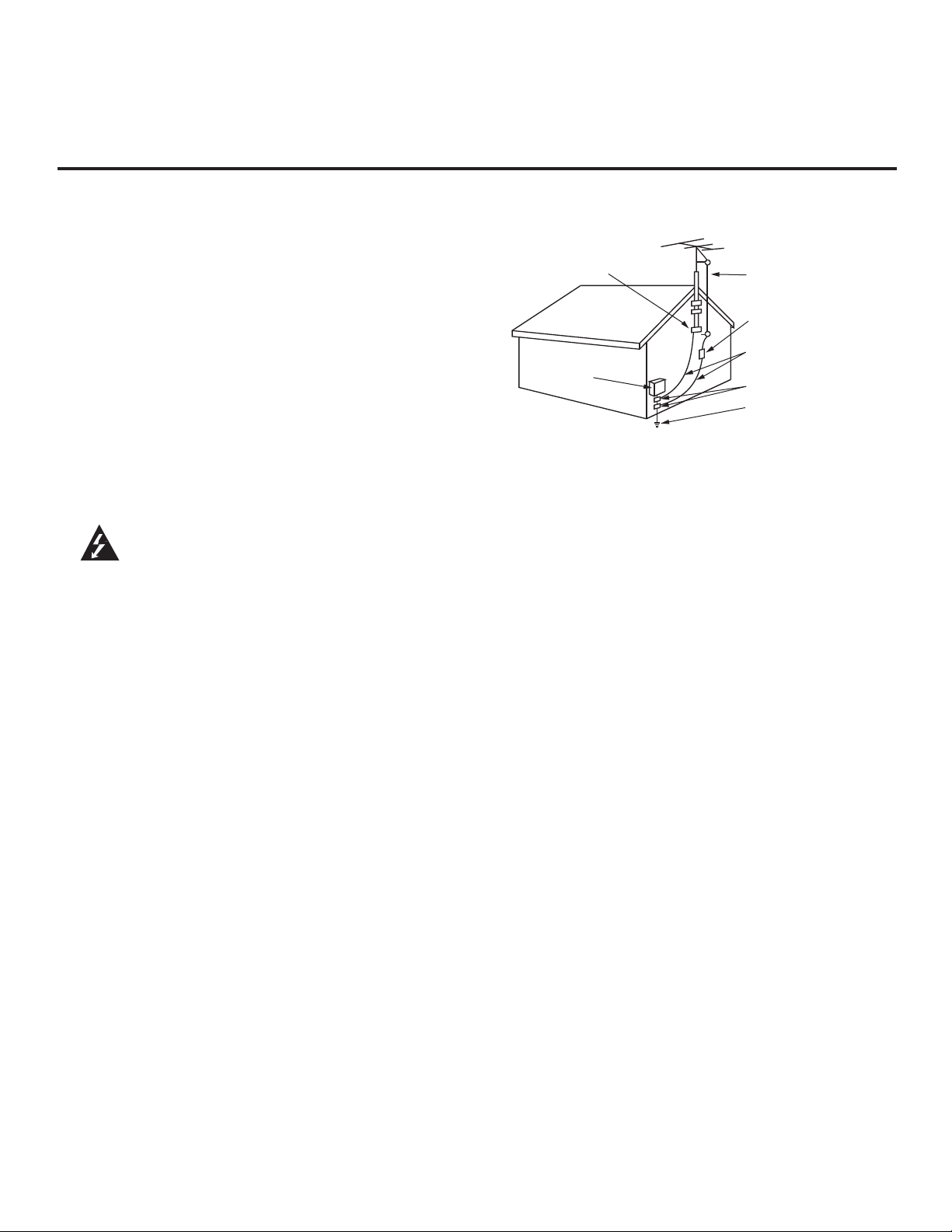
Antenna Grounding According to NEC, ANSI/NFPA 70
Ground Clamp
Electric Service
Equipment
Antenna Lead in Wire
Antenna Discharge Unit
(NEC Section 810-20)
Grounding Conductor
(NEC Section 810-21)
Ground Clamps
Power Service Grounding
Electrode System (NEC
Art 250, Part H)
22. Servicing
Do not attempt to service this product yourself as open-
ing or removing covers may expose you to dangerous
voltage or other hazards. Refer all servicing to qualified
service personnel.
23. Damage Requiring Service
Unplug this product from the wall outlet, and refer ser-
vicing to qualified service personnel under the following
conditions:
a. If the power-supply cord or plug is damaged.
b. If liquid has been spilled, or objects have fallen into
the product.
c. If the product has been exposed to rain or water.
d. If the product does not operate normally per the
operating instructions. Adjust only those controls
that are covered by the operating instructions, as an
improper adjustment of other controls may result in
damage and will often require extensive work by a
qualified technician to restore the product to its normal
operation.
e. If the product has been dropped or the cabinet has
been damaged.
f. If the product exhibits a distinct change in performance.
24. Replacement Parts
When replacement parts are required, be sure the ser-
vice technician uses replacement parts specified by the
manufacturer or the have the same characteristics as
the original part. Unauthorized substitutions may result
in fire, electric shock, or other hazards.
25. Safety Check
Upon completion of any service or repairs to this prod-
uct, ask the service technician to perform safety checks
to determine that the product is in proper operating
condition.
4
206-4124

Table of Contents
Table of Contents / Setup Checklist
Warnings . . . . . . . . . . . . . . . . . . . . . . . . . . . . . . . . . . . . . 2
Important Safety Instructions. . . . . . . . . . . . . . . . . . . . 3–4
Table of Contents / Setup Checklist . . . . . . . . . . . . . . . . 5
FMA-LG101 Description . . . . . . . . . . . . . . . . . . . . . . . . . 6
Creating an FMA Configuration File . . . . . . . . . . . . . . . . .7
FMA-LG101 Installation . . . . . . . . . . . . . . . . . . . . . . . . 8–9
Network Connection Settings for FMA-LG101
Configuration . . . . . . . . . . . . . . . . . . . . . . . . . . . . . . . . . 10
FMA-LG101 Configuration . . . . . . . . . . . . . . . . . . . .11–14
FMA-LG101 Troubleshooting . . . . . . . . . . . . . . . . . . . . 15
Specifications . . . . . . . . . . . . . . . . . . . . . . . . . . . . . . . . .16
Reference: FTG Device Firmware RF Downloader . . . .17
Flowchart: Creating an FMA Configuration File . . . . . . .18
Document Revision History / Notes . . . . . . . . . . . . . . . .19
Warranty . . . . . . . . . . . . . . . . . . . . . . . . . . . . . Back Cover
Setup Checklist
Installation and configuration of the Free-To-Guest (FTG) Management Appliance (FMA-LG101) requires the following
hardware, equipment, and software.
At the Head End
__ Contents of FMA-LG101 carton:
• FMA-LG101 unit (with attached rack mount brackets)
• Power supply (12V DC 1.25A)
• 75 ohm coaxial terminator (FMA-LG101 RF IN port termination)
• 7-foot Ethernet crossover cable (direct connect PC to confi gure FMA-LG101)
• 50 MHz low pass fi lter (6MLP-50)
__ Configuration of the FMA-LG101 requires a PC with an Ethernet port and the FTG Configuration Application
v5.0.0 or higher installed. FTG Configuration Application software is available online at:
www.LGcommercial.com/FTGSoftware.
At the Room
__ An LG TV must be equipped with one of the following FTG devices:
• EBL (Embedded b-LAN™)
• LMT7Z9 MPI card
• LMT7Z7 MPI card (requires fi rmware update) *
* Please contact the LG Sales team to obtain a Firmware Update (.mot) file. You can then use the Firmware Downloader
Utility available from the FMA-LG101 software web page to upload the latest firmware to the FTG device(s). Refer to the
“FTG Device Firmware RF Downloader” information in this document for detailed instructions.
Note: An HCS1410 FTG card is not compatible with the FMA-LG101.
206-4124
5

FMA-LG101 Description
The FMA-LG101 facilitates the delivery of Channel Lineup and Installer Menu settings to
guest room TVs via the RF distribution system, such that Channel Lineup or Installer Menu
settings can be updated without individual room visits. Every LG TV capable of receiving
the Channel Map broadcast from the FMA-LG101 will be configured with the same Channel
Lineup. Installer Menu settings are dependent on chassis model IDs; only the model(s)
whose Installer Menu settings are being broadcast will be affected. The FMA-LG101 can
broadcast multiple Installer Menu profiles to support the different chassis models connected
to the RF distribution system.
FTG Management Appliance (FMA) Configuration File
An FMA Configuration (.fma) file is required to update the FMA-LG101's broadcast data (i.e., FTG Channel
Map and FTG Installer Menu settings). Users can create an FMA Configuration file at any time on any PC on
which the FTG Configuration Application v5.0.0 or higher is installed (see next page).
FMA-LG101 Date and Time
• When the FMA-LG101 has been powered for at least 30 minutes, its current date and time will be maintained
during power loss for a minimum of nine hours.
• If the DST (US Daylight Saving Time) option is Enabled during confi guration, the FMA-LG101 will automati-
cally set the clock forward one hour at 2:00 AM on the second Sunday in March and set the clock back one
hour at 2:00 AM on the fi rst Sunday in November. These dates were established by Congress in the Energy
Policy Act of 2005.
FMA-LG101 Broadcast
Note: The RF distribution system must support 50.5 MHz RF transmission (downstream) from
the head end to the FTG device(s).
The FMA-LG101 will broadcast the Date and Time, the Channel Lineup, and any Installer Menu profi les every
fi ve minutes (300 seconds) by default. The broadcast rate is adjustable, but it is not recommended to set the
broadcast rate to fewer than 10 seconds. If an FTG device or TV is replaced in a room, the replacement, when
connected to the RF distribution system, will automatically be confi gured by the current data being broadcast
and will not require additional confi guration. *
* Replacement TV only: For the Installer Menu to be configured, the replacement TV must be the same model or a model
whose Installer Menu profile is already included in the broadcast.
6
206-4124

Creating an FMA Configuration File
Note: This section provides an overview of the procedure to create an FMA Configuration file. Refer to the
Free-To-Guest (FTG) Configuration Application manual for detailed instructions. For a visual representation
of the procedure, see the flowchart at the end of this document.
1. Install (if necessary) and launch the FTG Configuration Application (v5.0.0 or higher).
2. Create a new FTG Channel Map, or open an existing FTG Configuration (.rml) file. *
3. Click Configure in the menu bar, and select FMA to access the FMA Configuration Utility (see screen below).
(Tip: You can also use an existing FMA Configuration file as a basis for the new file, if appropriate. **)
4. To add an FTG Channel Map, click >> under FTG Channel Map to copy the current FTG Channel Map to
the FMA Configuration List.
5. To add FTG Installer Menu settings, click >> under FTG Installer Menu Settings to copy the current FTG
Installer Menu settings (if applicable) to the FMA Configuration List.
6. (Optional) Load default Installer Menu settings for selected model(s):
• Click the down arrow at the right of the Chassis fi eld under Installer Menu Templates, and select the
desired model from the drop-down list of available models.
• Click the Load button.
• Click >> under FTG Installer Menu Settings to copy selected model(s) settings to the FMA Confi guration List.
7. Click the Save button above the FMA Configuration List to save it to a (.fma) file for later use.
Note: The data referenced in the FMA Configuration List is a only snap-shot of the current FTG
Channel Map and FTG Installer Menu settings when copied to the list. If you make any change(s)
to the current data to be included in the FMA Configuration List, you will need to recopy Channel Map
and Installer Menu settings to the FMA Configuration List.
FMA Configuration List (data
Filename of opened
FTG Configuration file
Copy FTG Channel
Map to and from FMA
Configuration List.
Copy FTG Installer
Menu settings
to and from FMA
Configuration List.
Load default FTG
Installer Menu for
selected model(s).
ready for transfer to FMA)
FMA File options
Set the FMA clock
to the PC’s clock.
Set the FMA broadcast rate.
FMA Configuration
Transfer options
Confirm IP
address for FMA IP
Communication.
* Up to 141 logical channels can be mapped in the Channel Lineup to be broadcast by the FMA-LG101.
** Existing FMA or FTG Configuration files should be appropriate to the site for which you are creating the new FMA
Configuration file. Otherwise, build the new file from scratch.
206-4124
7

FMA-LG101 Installation
Refer to the following diagrams, and install the FMA-LG101 in
the equipment rack as described on page 9.
FMA-LG101
Front View
FMA-LG101 Front Panel LEDs
PWR: Illuminates when power
is applied to the unit.
RX: Illuminates when stored
configuration has been reset to
default due to data corruption.
TX: Flashes when data is being
transmitted on the RF OUT port.
ETHERNET
RX
PWR
PWR, RX,
and TX LEDs
Rack
Mount
Bracket
TX
Ethernet
Cable
FMA-LG101
Rear View
Rack
Mount
Bracket
Rack
Mount
Bracket
Rack
Mount
Bracket
x
RF OUT
RF IN
x
DC 12V
75 Ohm
Terminator
DC Power
Supply
50 MHz
Low Pass
Filter
RF Cable
8
206-4124

FMA-LG101 Installation (Cont.)
FMA-LG101 Installation Notes
• The AC outlet providing power must be installed near the FMA-LG101 and be easily accessible.
• The FMA-LG101 should be installed in a restricted access location.
Installing the FMA-LG101 in the Equipment Rack
Refer to the FMA-LG101 diagrams on page 8, and complete the following steps to install the FMA-LG101
in the equipment rack.
1. As shipped, the FMA-LG101 rack mount brackets are attached inward, covering the front panel of the
FMA-LG101 unit. Detach and then re-attach the rack mount brackets to the FMA-LG101 as shown in
the diagrams on the previous page.
2. Mount the FMA-LG101 in the equipment rack.
3. Complete all connections as indicated in the FMA-LG101 Rear and Front Panel Connections table
below.
4. Plug the power supply for the FMA-LG101 in to an AC outlet (or the rack power strip, if applicable), and
then connect the 12V DC output to the FMA-LG101.
5. Wait at least 30 seconds for the FMA-LG101 to power ON and obtain network settings from a DHCP
server or load its default network settings.
6. Confi gure the FMA-LG101 as described on the pages that follow.
FMA-LG101 Rear and Front Panel Connections
Port Name Connection
Rear Panel RF OUT Connect the 50 MHz low pass filter and coaxial RF cable from the RF
distribution system combiner. (The 50 MHz low pass filter protects RF
channels 2 and 3 from any potential RF interference produced by the
FMA-LG101.)
RF IN Not applicable; connect the 75 ohm terminator.
DC 12V Connect the 12V DC power supply shipped with the FMA-LG101.
Front Panel ETHERNET Make the appropriate connection based on the system setup:
• Network Ethernet connection: Connect an Ethernet straight-through
cable (not supplied) from the network. The FMA-LG101 must be connected to a network with a DHCP server before power is applied.
• Direct Ethernet connection: Connect the supplied Ethernet crossover
cable from a PC.
Refer to “FMA-LG101 Ethernet Connection/Network Options” on the
next page for further information.
206-4124
9

Network Connection Settings for FMA-LG101 Configuration
FMA-LG101 Ethernet Connection/Network Options
(see also Ethernet connection information on previous page, as necessary)
• The FMA-LG101 can operate as a DHCP client if a network DHCP server assigns it a valid IP address
for that network. Otherwise, the FMA-LG101 uses its factory default IP address. In order to operate as a
DHCP client, the FMA-LG101 must be connected via a straight-through Ethernet cable to a network with
a DHCP server before power is applied.
• If there is no DHCP server, or if the FMA-LG101 is con
cable, the
When the FMA-LG101 is using its default IP address, the confi guring PC must be on the same subnet
FMA-LG101. For example, the PC's network connection settings
FMA-LG101 will default to its factory IP address and subnet mask of 10.20.1.120 / 255.255.2
Setting the PC Network Connections
If the FMA-LG101 is connected to the
administrator for proper network
work, and then proceed to configure the FMA-LG101.
If you are using a direct Ethernet connection between the FMA-LG101 and the configuring PC, you must
complete the following procedure to set the PC network connections before you proceed to configure the
FMA-LG101.
network (i.e., the FMA-LG101 is a DHCP client), consult the network
settings. Set the PC’s network connections to provide access to the net-
nected directly to a PC via an Ethernet crossover
48.0.
as the
can be set as 10.20.1.90 / 255.255.248.0.
1. On the PC, navigate to Network Connections options, as applicable, per your operating system, i.e.,
Windows® XP, Windows Vista® or Windows 7. Refer to IT personnel or Windows documentation for
further information.
2. Right-click on the Local Area Connection icon in the Network Connections window, and select
Properties.
3. Double-click on Internet Protocol (TCP/IP) in the Local Area Connection Properties window.
4. In the Internet Protocol Properties window, select the Use the following IP address: radio button. Then:
• In the IP address fi eld, type an IP address from the following range: 10.20.1.81 to 10.20.1.92.
• Type 255.255.248.0 in the Subnet mask fi eld.
5. Click OK to close the Internet Protocol Properties window. (You can also close any additional network
connections windows at this time.)
10
206-4124

FMA-LG101 Configuration
Once you have completed the required steps to set the PC’s network connections, you can update the
FMA-LG101 using either the FTG Configuration Application software (v5.0.0 or higher) or the FMA-LG101
software web page.
Experienced installers can refer to the FMA-LG101 configuration quick reference overviews below if
extended directions are not required. Otherwise, proceed to the appropriate section depending on whether
you are using the FTG Configuration Application software or the FMA-LG101 software web page.
FMA-LG101 Configuration Prerequisites
• The FMA-LG101 must be installed in the equipment rack prior to confi guration (see FMA-LG101 installa-
tion and cabling information on previous pages).
• You will need to know the IP address of the FMA-LG101 (see “FMA-LG101 Ethernet Connection/Network
Options” on previous page).
Network Ethernet connection: Consult the network administrator to obtain the IP address that has been
assigned by a DHCP server to the FMA-LG101.
Direct Ethernet connection: The FMA-LG101 uses its default IP address (10.20.1.120).
• Create a new or identify an existing FMA Confi guration (.fma) fi le to use for updating the FMA-LG101 (see
“Creating an FMA Confi guration File” on page 7, as necessary).
Overview
FMA-LG101 Configuration Quick Reference (FTG Configuration Application
Software)
1. Launch the FTG Confi guration Application (v5.0.0 or higher), and access the FMA Confi guration Utility .
2. Set the FMA Utility’s IP address.
3. “Write” the appropriate FMA Confi guration fi le to the FMA-LG101.
4. Set the FMA clock. (Note that date and time must be set on the PC running the FTG Configuration Ap-
plication prior to an attempt to set the FMA clock.)
5. Set the FMA broadcast rate.
6. Connect the FMA-LG101 to the RF distribution system as described on page 14.
FMA-LG101 Configuration Quick Reference (FMA-LG101 Software Web Page)
1. Launch a web browser, type the appropriate IP address in the browser’s address bar, and press Enter.
2. Set the date and time parameters and the broadcast rate, and then update the FMA-LG101.
3. Update the FMA-LG101 with an FMA Configuration file.
4. Connect the FMA-LG101 to the RF distribution system as described on page 14.
206-4124
11

FMA-LG101 Configuration
Using the FTG Configuration Application Software
1. Launch the FTG Configuration Application (v5.0.0 or higher).
2. Click Configure in the menu bar, and select FMA to access the FMA Configuration Utility (see screen
sample on page 7). Then, set the FMA Utility’s IP address, update the FMA-LG101 configuration, and
configure the FMA clock and broadcast rate as described below.
Set the FMA Utility’s IP Address
The IP address specified in the FMA IP Communication section at the bottom right of the screen must be
set to the IP address of the FMA (see “FMA Configuration Prerequisites” on previous page).
a. If you need to modify the FMA Utility’s IP address, double-click anywhere within the IP Address field.
b. In the pop-up box, enter the appropriate IP address, and then click OK. Or, to restore the IP address
to the default (10.20.1.120), click Default and then OK.
Update the FMA-LG101 with an FMA Configuration File
a. Use the current contents of the FMA Configuration List, or click the Open button above the FMA
Configuration List to open an existing FMA Configuration (.fma) file.
Note: When opening an existing FMA file, reconfirm the FMA Utility’s IP address, since the FMA file
when saved, had an IP address associated with it.
b. Click the Write button in the FMA Configuration Transfer section of the screen to send the current
contents of the FMA Configuration List to the FMA-LG101.
c. Once the system processes your request, you will see a pop-up report message to indicate
success. Click OK to close the report message box and continue.
Set the FMA Clock
The facility for setting the FMA clock is on the right side of the FMA Confi guration Utility screen. Date and
time must be set on the PC running the FTG Configuration Application prior to an attempt to set the FMA
clock.
a. Auto DST: When checked, the FMA’s clock automatically observes Daylight Saving Time.
b. Click the Set Clock button to set the date and time of the FMA to the PC’s date and time.
c. A pop-up Date & Time window displays a snapshot of the PC's current date and time. Click Yes to
synchronize the FMA’s clock with the PC's clock.
d. Once the system processes the request, you will see a pop-up report message to indicate success.
Click OK to close the report message box and continue.
Set the FMA Broadcast Rate
The facility for setting the FMA broadcast rate is on the right side of the FMA Configuration Utility screen.
This facility sets the interval, in seconds, at which to broadcast the Date, Time, Channel Lineup, and
Installer Menu settings. (FMA-LG101 factory default broadcast rate is 300 seconds.)
a. Select the number of seconds (1–999) for the broadcast rate (“0” disables broadcasting). Note that it
is not recommended to set the broadcast rate to fewer than 10 seconds.
b. Click the Set Rate button to set the selected rate of broadcast in the FMA.
c. Once the system processes your request, you will see a pop-up report message to indicate
success. Click OK to close the report message box.
3. Click File and then Exit in the menu bar to exit the FMA Configuration Utility.
4. Connect the FMA-LG101 to the RF distribution system as described on page 14.
12
206-4124

FMA-LG101 Configuration
Using the FMA-LG101 Software Web Page
1. Launch a web browser, and type http://ipaddress in the browser’s address bar, where ipaddress is either
the network IP address assigned by a DHCP server to the FMA-LG101 or the FMA-LG101’s default IP address (see “FMA-LG101 Configuration Prerequisites” on page 11). Then, press Enter.
FMA-LG101 Software Web
Page Main Screen
Fields at the bottom left corner
of the screen identify the FMALG101 firmware version, IP
address, and MAC address.
2. Once you have accessed the FMA-LG101 web page, proceed to the configuration procedures that follow.
Set the Date and Time Configuration Fields for the FMA-LG101
a. Set the following fields, as applicable.
• Month: Click the down arrow at the right of the fi eld, and select the appropriate month from the drop-
down list.
• Day of Month (1–31) and Year (2009–2047): Type the appropriate values in these fi elds.
• Hour (0–23) and Minutes (0–59): Type the appropriate values in these fi elds. Note that the hour fi eld
is based on a 24-hour clock.
• DST Enable?: “Yes” (default) enables or “No” disables automatic US Daylight Saving Time observance.
b. The Rate (0–999) field sets the interval, in seconds, at which to broadcast the Date, Time, Channel
Lineup, and Installer Menu settings. (FMA-LG101 factory default broadcast rate is 300 seconds.) Type
the number of seconds (1–999) for the broadcast rate (“0” disables broadcasting). Note that it is not
recommended to set the broadcast rate to fewer than 10 seconds.
c. Click the Update Date & Time button.
Note: After you click the Update Date & Time button, the screen will begin to refresh/reload.
Wait for the screen to com
pletely reload before proceeding. To refresh the
date and time to
the current settings, click the green Refresh button to the right of the Update Date & Time button.
Do NOT use the web browser Refresh button!
(Continued on next page)
206-4124
13

FMA-LG101 Configuration
Using the FMA-LG101 Software Web Page (Cont.) / Connect the FMA-LG101 to the RF
Distribution System
(Continued from previous page)
Update the FMA-LG101 with an FMA Configuration File
a. Under the Channel and TV Configuration section, click the Browse button.
b. Browse to the desired FMA Configuration (.fma) file. Select the file, and click the Open button.
c. Confirm that the path shown in the Config File To Update field is correct for the FMA
Configuration file selected, and then click the Update Config button to update the configuration
on the FMA-LG101.
Note: After you click the Update Config button, the screen will begin to refresh/reload. This process
may take a few seconds to completely transfer the file and save to memory. Wait for the screen to
completely reload before proceeding.
3. Connect the FMA-LG101 to the RF distribution system as described below.
Connect the FMA-LG101 to the RF Distribution System
Note: The RF distribution system must support 50.5 MHz RF transmission (downstream)
from the head end to the FTG device(s).
1. Connect the FMA-LG101 RF OUT to the RF distribution system.
Note: The 50 MHz low pass filter (6MLP-50) provided should be installed to protect RF channels 2
and 3 from any potential RF interference produced by the FMA-LG101.
2. Verify that the 50.5 MHz RF signal level is between +3 dBmV and +10 dBmV at the FTG device(s).
Note that additional equipment may be required to adjust the signal level. If the signal level is not within the recommended range, communications will be negatively affected, resulting in a partial or missing Channel Lineup and/or Installer Menu settings data.
14
206-4124

FMA-LG101 Troubleshooting
The following table provides information on general symptoms and solutions related to the FMA-LG101.
For many of the troubleshooting steps, you will need to know the IP address of the FMA-LG101. Refer to “FMA-LG101
Ethernet Connection/Network Options” on page 11 for further information.
Symptom Solution
The OSD/call letters do not
display in the guest room(s).
When the TV is turned ON, it is
in split screen mode.
The date/time of the TV(s) is
incorrect.
If the issue affects all rooms, verify that the FMA Confi guration (.fma) fi le uploaded
to the FMA-LG101 was properly confi gured.
If the issue is restricted to a single room:
• Wait fi ve minutes (default Broadcast Rate setting) for the FMA-LG101 to
re-broadcast the Channel Lineup and re-test.
• Check the coaxial connections and RF signal levels in the room.
• Replace the FTG device or TV, if possible.
Always configure Installer Menu item 004 STRT CHANNEL (Start Channel) to a
channel or Installer Menu item 046 STRT AUX SRCE (Start Aux Source) to a nonRJP Aux input.
If an LG TV is accompanied by a Remote Jack Pack (RJP) system, Installer Menu
item 093 RJP AVAILABLE is NOT set to 0 (zero). If the Start Channel is set to 0
(zero), which indicates to reference the Start Aux Source, and the Start Aux Source
is set to an RJP Aux, when the TV is turned ON, it will be in split screen mode.
• Verify that the FMA-LG101 is connected to a steady and reliable power source.
The FMA-LG101 will retain the current date and time settings for at least nine
hours after losing power. Beyond nine hours of power loss, the date and time
settings may need to be reconfi gured.
• Verify that the DST (US Daylight Saving Time) option is set appropriately.
• Set the FMA clock (date and time settings) using the FTG Confi guration Application
or the FMA-LG101 software web page.
The PC cannot access the
FMA-LG101 via the Ethernet
interface.
206-4124
• Verify that the PC's network settings are properly set for a direct connection or a
network connection.
• Verify that the appropriate Ethernet cable is connected properly and in good
condition.
• If the confi guring PC is running Windows Vista or Windows 7, resetting the power
on the FMA-LG101 while the PC is connected may cause a network confl ict issue.
To correct a network confl ict, disable and then enable the network interface on the
PC, or disconnect and reconnect network cables.
• Ping the FMA-LG101 IP address (“10.20.1.120” for direct connection or consult
network administrator for network connection). If the FMA-LG101 does not
respond, the FMA-LG101 will need to be replaced.
15

Specifications
Dimensions
Height: 1.75 inches (44.45 mm)
Width: 7.25 inches (184.15 mm) (19 inches with rack mount brackets attached)
Depth: 4.5 inches (114.3 mm)
Weight: 2 pounds (0.91 kgrms) (with mounting brackets)
Environmental Storage Conditions
Temperature: -20° to 70° degrees Celsius
-4° to 158° degrees Fahrenheit
Humidity: 20% to 80%
Environmental Operating Conditions
Temperature: 0° to 45° degrees Celsius
32° to 113° degrees Fahrenheit
Humidity: 10% to 90% RH, non-condensing
Inputs/Outputs
Rear
DC 12V: 2.1 mm jack
RF IN: Type “F” female
RF OUT: Type “F” female
Front
Ethernet Port: 10BaseT, RJ-45
RF Output
Modulation: FSK
Data Rate: 62.5 Kbps
Frequency for Data Low: 49.5 MHz +/- 50 kHz
Frequency for Data High: 50.5 MHz +/- 50 kHz
Impedance: 75 ohms +/- 5%
RF Output Level: 50 dBmV +/- 2 dBmV
Power Supply
Input: 100 to 240 VAC @ 50 to 60 Hz
Output: +12V DC @ 1.25 Amps
Note: Design and specifi cations subject to change without prior notice.
16
206-4124

Reference: FTG Device Firmware RF Downloader
The FMA-LG101 software web page provides a utility to download FTG device (EBL, LMT7Z9, or LMT7Z7)
fi rmware via the RF distribution system. Use this procedure to update the fi rmware on the FTG device(s).
Note that TVs with FTG device(s) will not be operable during fi rmware download and update (approximately fi ve
minutes).
1. Launch a web browser, and type http://ipaddress in the browser’s address bar, where ipaddress is either
the network IP address assigned by a DHCP server to the FMA-LG101 or the FMA-LG101’s default IP address (see “FMA-LG101 Configuration Prerequisites” information on page 11). Then, press Enter.
2. Click the FTG Device Firmware RF Downloader link at the bottom of the FMA-LG101 Main Page.
3. Complete the pop-up Login fields as follows:
• User name: Type lg.
• Password: Type service.
Then, click OK to continue to the FTG Device Firmware RF Downloader web page.
4. Under the Firmware File Upload section, click the Browse button.
5. Browse to the desired Firmware (.mot) fi le. Select the fi le, and click the Open button.
6. Confi rm that the path shown in the Firmware File To Upload fi eld is correct for the Firmware fi le selected,
and then click the Upload File button to upload the fi le to the FMA-LG101.
Note: After you click the Upload File button, the screen will begin to refresh/reload. The upload process may
take a few seconds. Wait for the screen to completely reload before proceeding.
7. In the RF Downloader section, the Version indicator should now show the fi rmware version number that
corresponds to the Firmware fi le you just uploaded. Click the check box at the right of the Version number to
confi rm its accuracy, and then click the Download button.
The broadcast of fi rmware completes in approximately two minutes, and the FTG device will require an additional
two minutes to update fi rmware, after which the TV will become operable again.
206-4124
17

Flowchart: Creating an FMA Configuration File
This fl owchart provides a visual overview of the steps to create an FMA Confi guration (.fma) fi le. Refer to the Free-To-
Guest (FTG) Confi guration Application manual for further procedural information.
Launch FTG
Conguration
Application
(v5.0.0 or higher).
Note: Existing FMA or FTG
Conguration les should be
appropriate to the site for
which you are creating the
new FMA Conguration le.
Otherwise, build the new le
from scratch.
Access FMA
A
Conguration Utility,
and open FMA
Conguration le.
(Optional) Copy FTG
Channel Map to
current settings and
edit as necessary.
Existing FMA
Conguration (.fma)
le available for basis of
new .fma le?
No
Existing FTG
Conguration (.rml)
le(s) available?
No
Go to
Chart C
FMA
Conguration le
contains Installer Menu
settings for desired
model(s)?
No
Load default FTG
Installer Menu settings
for selected model(s).
Yes
Go to
Chart A
Yes
Go to
Chart B
(Optional) Load default
Yes
FTG Installer Menu settings
for additional model(s), and/or
edit Installer Menu settings.
(Optional) Edit Installer
Menu settings to
desired values.
Go to
Chart D
18
FTG
B
C
D
* Up to 141 logical channels can be mapped in the Channel Lineup to be broadcast by the FMA-LG101.
** (Optional) Repeat this step to add Installer Menu settings for additional models.
Open FTG
Conguration le.
Create FTG
Channel Map. *
If necessary,
switch to FMA
Conguration Utility.
Access the FMA
Conguration Utility.
Access the FMA
Conguration Utility.
Copy current FTG
Channel Map to
FMA Conguration List.
Conguration le
contains both Channel
Map and Installer Menu
settings?
No
As applicable, create an
FTG Channel Map,
load default FTG Installer
Menu settings for
selected model(s). *
Load default FTG
Installer Menu settings
for selected model(s).
Copy current FTG Installer
Menu settings to FMA
Conguration List. **
(Optional) Edit FTG Channel
Map and/or Installer Menu
Yes
settings and/or load default
FTG Installer Menu settings
for selected model(s).
(Optional) Edit Installer
Menu settings to
desired values.
(Optional) Edit Installer
Menu settings to
desired values.
Save the FMA
Conguration List to
(.fma) le for later use.
Go to
Chart D
Go to
Chart D
206-4124

Document Revision History / Notes
Document Revision History
Date Description
April 2010 Revision A: New document
Documentation is available online at: www.LGcommercial.com/product/FMA-LG101. Click the Downloads &
Images tab on the FMA-LG101 page, and select the required document from the Downloads list.
Notes
206-4124
19

FMA-LG101 Warranty
Broadcast Products Welcome to the LG family! We believe that you will be pleased with your new FMA-LG101. Please read this
warranty carefully, it is a “LIMITED WARRANTY” as defined under Federal Law. This warranty gives you
specific legal rights, and you may also have other rights that vary from state-to-state within the U.S.A.
LG’s RESPONSIBILITY
Warranty Term One year parts and labor from date of purchase or delivery date.
Parts New or remanufactured replacements for factory-defective parts may be used. Such replacement parts are
warranted for the remaining portion of the original warranty period.
Warranty Service Warranty service is provided at LG. Customer pays for shipping charges to LG; LG pays for return shipping
charges to return FMA-LG101 to customer. Call 1-888-865-3026 for further information.
Not Covered This warranty covers manufacturing defects and does not cover installation, adjustment of customer con-
trols, installation or repair of antenna systems, cable converters or cable company-supplied equipment; it
also does not cover damage due to misuse, abuse, negligence, acts of God or other causes beyond the
control of LG. Any alteration of the product after manufacture voids this warranty in its entirety.
THIS WARRANTY IS IN LIEU OF ANY OTHER WARRANTY, EXPRESS OR IMPLIED, INCLUDING
WITHOUT LIMITATION, ANY WARRANTY OF MERCHANTABILITY OR FITNESS FOR A PARTICULAR
PURPOSE, AND LG SHALL NOT BE LIABLE FOR ANY CONSEQUENTIAL, INDIRECT, OR
INCIDENTAL DAMAGES OF ANY KIND, INCLUDING LOST REVENUES OR PROFITS IN CONNECTION
WITH THIS PRODUCT. SOME STATES DO NOT ALLOW LIMITATIONS ON HOW LONG AN IMPLIED
WARRANTY LASTS OR THE EXCLUSION OR LIMITATION OF INCIDENTAL OR CONSEQUENTIAL
DAMAGES, SO THE ABOVE LIMITATIONS OR EXCLUSIONS MAY NOT APPLY TO YOU.
OWNER’S RESPONSIBILITY
Effective Warranty Date Warranty begins on the date of delivery of the FMA-LG101.
For your convenience, keep the dealer’s dated bill of sale or delivery ticket as evidence of the purchase date.
Installation Guide Read the Installation & Configuration Guide carefully so that you will understand the operation of the FMA-
LG101 and how to configure it.
Antenna Reception problems caused by inadequate antenna or faulty antenna connections are the owner’s responsibility.
Warranty Service For warranty service information,
ity (see above) will be provided without charge. Other service is at the owner’s expense. If you have any
problem in obtaining satisfactory warranty service, call 1-888-865-3026.
You must provide the model number, serial number and date of purchase or date of original installation.
call 1-888-865-3026. Parts and service labor that are LG’s responsibil-
For Customer Support/Service, please call:
1-888-865-3026
www.LGcommercial.com
b-LAN is a trademark of LodgeNet Interactive Corporation. All other trademarks
or registered trademarks are the property of their respective owners.
© Copyright 2010, LG Electronics U.S.A., Inc.
206-4124
Revision A
 Loading...