

Page 1

11SP 4247” LCD TV Power specification
Specification
Specification
Rev 1.3
6
Date: 2012. 08. 15
Page 2
11SP 4247” LCD TV Power specification
1. INTRODUCTION
1.1 Scope
This approval is the description related to every electrical and structural specifications
and reliability For Power Supply Unit used on 4247 inch LGE LED TV.
1.2 Customers product related items
Product : Power Supply Unit
Part code : EAY62171601
1.3 Product name
Product name : LGP4247-11SPL
Revision code : 1.3
2. SPECIFICATION
Rev 1.3
2.1 Input Requirements
Nominal Input Voltage AC 100V to AC 240V
Input Voltage Variation AC 90V to AC 264V
Under 3.5Arms . (at 100Vac & Nominal Load)
Input Current
Under 1.5Arms . (at 240Vac & Nominal Load)
Nominal Frequency 50 / 60 Hz
Frequency Variation Range 47 Hz to 63 Hz
Phase Single
Leakage Current 0.7mA_peak. (100Vac ~ 240Vac)
Surge Immunity ±
4kV / 1000ns / 0˚
to 360˚
Hold-up Time More than 20ms at 100Vac and maximum output load
Lightning Surge 2kA Normal, Common Mode
80A zero-peak max
Inrush Current
at cold start and any specified line, load, temperature conditions.
2.1.1 Power Factor
over than 0.9 at 90 – 264Vac & max load condition
7
Date: 2012. 08. 15
Page 3
11SP 4247” LCD TV Power specification
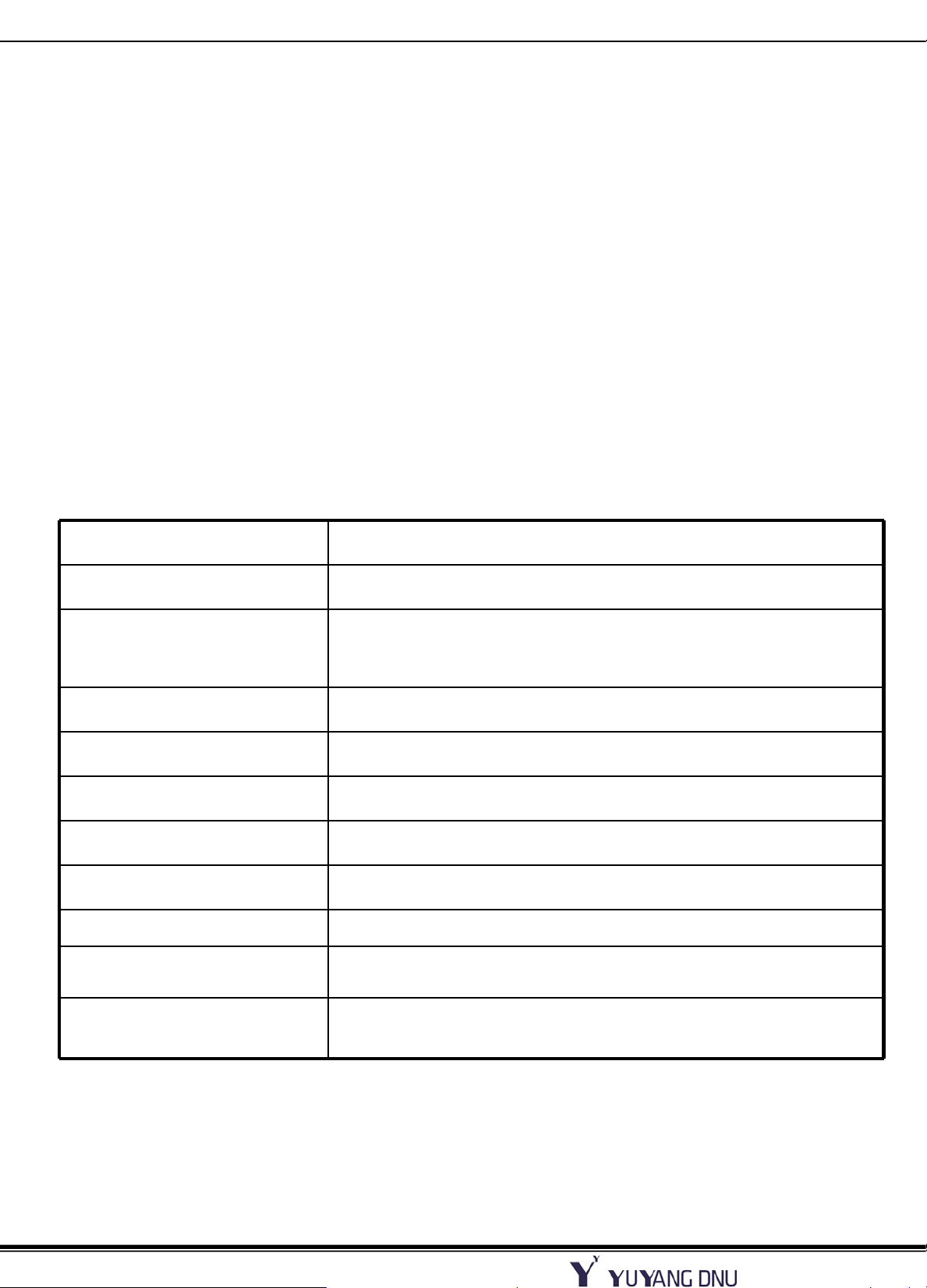
2.2 Power Output Characteristics
Rev 1.3
Output
3.5V
Voltage
Variable range
[V]
0.09W Under(6mA) - -
Rated Current
(Min, Max)
[Amean]
Voltage
Regulation
[V]
Ripple
Voltage
[mVp_p]
3.325V ~ 3.675V
(STBY)
12V 11.4V ~ 12.6V 3 (0.3~3 ±
24V 22.8V ~ 25.2V 4.1 (0.1~4.1) ±
2 (0.001~2) (ON condition) ±
5% 250 mVp_p
5% 350 mVp_p
5% 500 mVp_p
* On Condition : In a moment of Power_ON Signal activated, the current of 3.5V output should be
limited within 40mA(Max) at LCD TV condition for stability.
Do not turn “Power_ON” Signal on at the load condition of 3.5V output, more than 40mA.
* Total regulation for each output circuit includes the results of input voltage variation,
load variation, warm-up drift and temperature change.
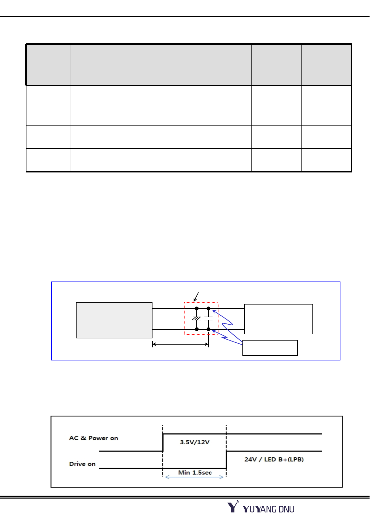
* The following instruments shall be used for measuring ripple noise.
1. Probe having impedance ratio of 1:1.
2. Oscilloscope having frequency characteristic of 100MHz or more.
- Test Point : power output each pin
Add Electrolytic Capacitor 47㎌ + 0.1㎌
Power Supply Unit
Output Voltage
700mm
※ Ripple and noise are measured at the end of output cable which are added a 0.1uF ceramic
capacitor and 47uF electrolytic capacitor. ( connected parallel )
+
Load
Oscilloscope
Measurement point
* Power turn on system (Only E/Load condition)
If Main Board is opened, that is electrical load condition,
drive on signal must be turn on after about 1.5s behind power on signal
8
Date: 2012. 08. 15
Page 4
11SP 4247” LCD TV Power specification
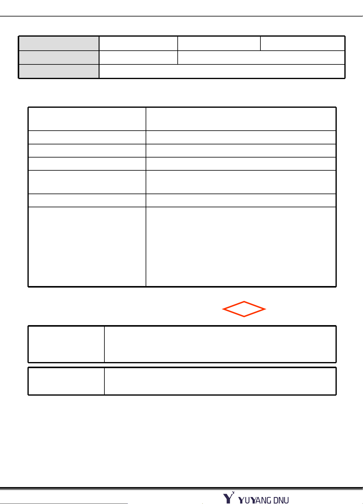
2.2.1 Stand By Power Consumption
Output Voltage 3.5V (STBY) 12V 24V
Load [A] 0.006 Don’t Care (Power-Off)
Wattage [W] Less than 0.09Under (230Vac / 50Hz)
2.3 Environment Requirement
Operating Temperature Range -10℃ to 40℃
(60℃:No Hardware Failure, TV SET Condition)
Operating Humidity Range 30 to 85 %
Storage Temperature Range -25 to 85 deg.
Storage humidity Range 5 to 90 %
Rev 1.3
MTBF
50,000 hour
(Mean Time Between Failure)
Cooling Condition Natural Air
Shock 98 ㎨
Shock test consists of pivoting the power supply, from
one edge of it’s bottom side, on a flat surface
(such as wood having thickness of 10mm or more) and
allowing the opposite edge to fall from a height of 50mm
to this surface.
The test is performed three times on each edge of the
bottom side of the power supply
2.4 Dielectric Strength Voltage and Insulation Resistance
Dielectric
Strength Voltage
AC-DC 1.5K VAC 3 SEC 10 mA.
Between Primary and All Secondary Circuits.
Safety
Insulation
Resistance
Insulation resistance shall be more than 8M ohm (at DC 500V)
Between Primary Live, Neutral line and Secondary.
* Above tests are performed at room temperature in non-condensing atmospheric
conditions
* Frame grounds are connected to secondary circuits.
2.5 Burn-in
More than 0.5 hours at 45℃(±5℃), Normal input voltage.
AC on/off must be test 1 time after burn-in.
80% Load of specification.
9
Date: 2012. 08. 15
Page 5

11SP 4247” LCD TV Power specification
2.6 Interface
Appellation Explanation Signal Direction Action
Rev 1.3
POWER ON Vcc Circuit ON/OFF Input
2.7 Product Safety
Safety
Design to meet the requirements as follows
Safety Standards to be applied
UL60950, IEC60950, IEC60065 and 60950
Design to meet the requirements as follows
EMI/RFI Standards to be applied
FCC and EN55020, EN55013 Class B
with 4dB minimum margin.
2.8 Construction
Weight Less than 1.0kg
Unit Size 290(W) X 240(D) X 12.9(H)
Hi : Vcc ON
Low : Vcc OFF
2.9 Function of protection
Trip point
Protection Output Circuit
Min Max
STBY 3.5V 3.0A 6.0A Auto Re-start
Over Current
12V 8.0A 28.4A Latch
24V 5.0A 14.2A Latch
STBY 3.5V - Auto Re-start
Short Circuit
12V - Latch
24V - Latch
* This Power Supply has above-mentioned protections.
* Short circuit protection between different output terminals is not considered.
* Trip point for over voltage indicates the operating point when the output voltage
slowly increases.
* The conditions of Over Current measurement
Multi output(3.5V,12V,24V) is nominal load state except an over current
measurement.
Notes
10
Date: 2012. 08. 15
Page 6

11SP 4247” LCD TV Power specification
2.10 Sound Noise Characteristics.
PSU Noise Specification
22.5 dB(a) / 20.u Pa 2.0E-5 Pa
(1/1 octave, A-weighting, to 1khz ~ 16khz Total overall
Measure Location : Anechoic Room
Measure Condition : At a distance of 60cm mic
Full white pattern, at AC 110V/220V
The max specification
(measure 3 points, at PSU center and left & right on the side)
Rev 1.3
11
Date: 2012. 08. 15
Page 7

11SP 4247” LCD TV Power specification
2.11 Connector Specification
2.11.1 Connectors Usage
Rev 1.3
P201
Type : SMAW200-H24S2
Maker : YEON-HO
Pin No. Signal Pin No. Signal
1 POWER-ON 2 24V
3 24V 4 24V
5 GND 6 GND
7 GND 8 GND
9 3.5V 10 3.5V
11 3.5V 12 3.5V
13 GND 14 GND
15 GND 16 N.C
17 12V 18 INV ON/OFF
19 12V 20 A-DIM
P202
Type : 20010WR-H14B/C
Maker : YEON-HO
Pin No. Signal
1 24V
2 24V
3 24V
4 24V
5 24V
6 GND
7 GND
8 GND
9 GND
10 GND
21 12V 22 P-DIM
23 N.C 24 ERROR
SK100
Type : 90011WR-H03D
Maker : YEON-HO
Pin No. Signal
1 LIVE
2 F.G
3 NEUTRAL
11 ERROR
12 INV ON/OFF
13 A-DIM
14 P-DIM
12
Date: 2012. 08. 15
Page 8

11SP 4247” LCD TV Power specification
Rev 1.3
2.12 PCB Dimension.
4.5mm
4.5mm
240
290
4.5mm
4.5mm
9.0mm
(Tolerance ±0.5mm)
PCB : 1.6mm
SMD Holder : 2.5mm (Tolerance ±0.4mm)
Lead cutting : 2.3mm
(Except T101, L601 Body : 2.3mm+0.5mm , GH : 2.5mm +0.5mm)
13
Date: 2012. 08. 15
Page 9

11SP 4247” LCD TV Power specification
2.13 Apply to the Eyelet point.(LGP4247-11SPL)
Apply to the Eyelet point 2.0Φ
Apply to the small Eyelet point 1.6Φ
EL39,EL40,EL41,EL42,EL45,EL46,EL47,EL48,EL49,EL50,EL51,EL52,EL58,EL59 (32EA)
: EL1,EL2,EL9,EL10,EL19,EL20,EL29,EL30,EL35,EL36,EL37,EL38,EL53,EL54,EL55,EL56,EL61 (17EA)
: EL3,EL4,EL5,EL6,EL7,EL8,EL11,EL12,EL15,EL16,EL17,EL18,EL21,EL22,EL31,EL32,EL33,EL34,
Rev 1.3
14
Date: 2012. 08. 15
Page 10

11SP 4247” LCD TV Power specification
2.14 Electrical Characteristics
No. Test Item Test method
Rev 1.3
Intermittent
1
Operation stability
Test
Low temperature
2
operation
Low temperature
3
Storage test Leave
At low temperature
The switching regulator shall ON/OFF for 20,000 time at an
Interval of 10 sec at maximum load, after that electrical
Characteristics shall be satisfied.
The switching regulator is left at the operating guarantee
Minimum temperature for 2 hours without applying electricity.
After that power shall be turned on, and then the electrical
Characteristics shall be satisfied.
The switching regulator is left at minimum storage
Temperature for 96 hours or more.
Then the switching regulator is left at a room temperature and
humidity for 1 hour or more, after that electrical characteristics
shall be satisfied.
The switching regulator is 10 consecutive temperature cycle that
shown below is performed and then leave them at room
temperature and humidity for 1 hour or more.
After that, electrical characteristics shall be satisfied.
Time Temperature
Heat cycle storage
4
test
5 Heat shock test
30 minutes 25℃
30 minutes 25℃ -> -20℃
60 minutes Minimum storage temperature (-20℃)
30 minutes -20℃ -> 25℃
30 minutes 25℃
30 minutes 25℃ -> 70℃
60 minutes Maximum storage temperature (70℃)
30 minutes 70℃ -> 25℃
Heat shock test performed under following conditions without
applying electricity and then leave them at room temperature and
humidity for 1 hour or more.
After that, electrical characteristics shall be satisfied.
Condition : -45℃(30minutes), 120℃(30minutes),
Switching time : Less than 5 minutes, 200 cycles.
15
Date: 2012. 08. 15
Page 11

11SP 4247” LCD TV Power specification
2.15 Mechanical Characteristics
No. Test Item Test method
There shall be no contaminant or dirt on the switching regulator
which has adverse effect on electrical characteristics.
1 Appearance
There shall be no excessive unevenness or scratches on the
plated or painted surface.
While applying electricity :
Vibration frequency : 5 ~ 100Hz
Acceleration : 4.9 m/s∧2
Vibration in X,Y,Z direction for 30 minutes
Rev 1.3
2 Vibration
3 Shock
While applying electricity :
Vibration frequency : 5 ~ 100Hz
Acceleration : 14.7 m/s∧2
Vibration in X,Y,Z direction for 30 minutes
After that electrical characteristics shall be satisfied.
There shall be no damage to appearance and construction.
Shock : 98 m/s∧2
On the oak more than 10mm thickness with the flat face, raise
the one side for 50mm, and it carries out each side free fail for
three sides.
There shall be no damage to appearance and construction.
16
Date: 2012. 08. 15
 Loading...