


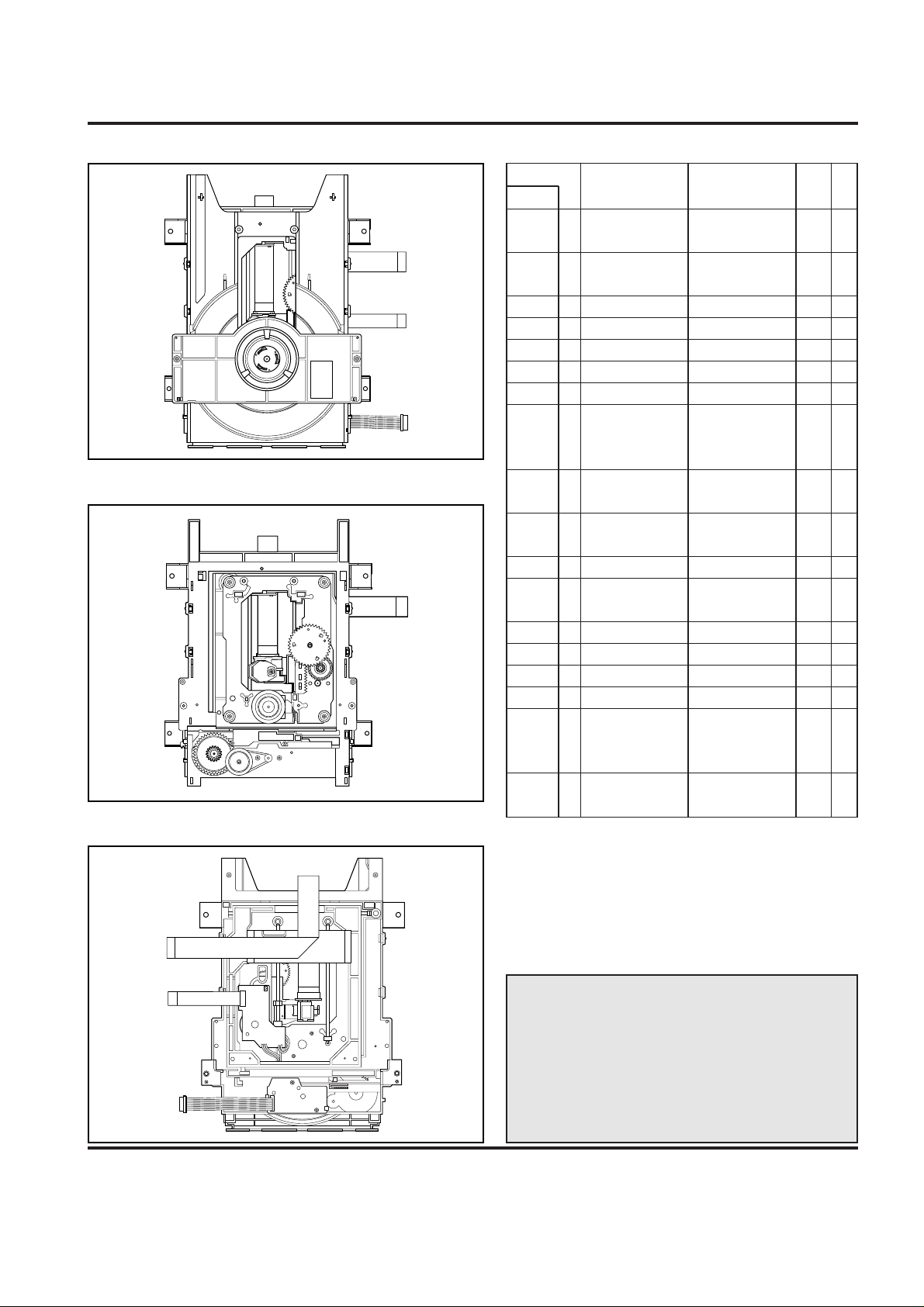
• Top View..................................................4-1
• Top View(without Tray Disc).................4-1
• Bottom View ...........................................4-1
1. Holder Clamp ....................................4-2
1-1. Clamp Assembly Disc.......................4-2
1-1-1. Plate Clamp..................................4-2
1-1-2. Magnet Clamp ..............................4-2
1-1-3. Clamp Upper.................................4-2
2. Tray Disc...........................................4-2
3. Base Assembly Sled........................4-3
3-1. Gear Assembly Feed........................4-3
3-2. Gear Assembly Middle......................4-3
3-3. Gear Assembly Rack........................4-3
4. Rubber Rear ......................................4-3
5. Frame Assembly Up/Down..............4-4
6. Belt Loading......................................4-4
7. Gear Pulley .......................................4-4
8. Gear Loading....................................4-4
9. Guide Up/Down.................................4-4
10. PWB Assembly Loading................4-4
11. Base Main........................................4-4
1. Tools and Fixtures for SVC.............4-5
2. Install Process..................................4-5
3. Adjustment Process.........................4-6
1. Deck Mechanism Exploded View....4-7
CONTENTS
SECTION 4 MECHANISM
DECK MECHANISM PARTS
LOCATIONS
EXPLODED VIEW
DECK MECHANISM ADJUSTMENT
DECK MECHANISM
DISASSEMBLY
4-1
DECK MECHANISM PARTS LOCATION
Starting No.
1
1, 2
1, 2, 3
1, 2, 3, 4
1
1, 6
1, 2, 6
1, 2, 6, 8
1, 2, 6, 8,
9
1, 2, 7
1, 2, 7
1, 2
1, 2 ,13
1, 2, 13, 14
1, 2, 7, 12, 13, 14
1, 2, 13
1, 2, 7, 12, 13,
14, 15, 16, 17
1
2
3
4
5
6
7
8
9
10
11
12
13
14
15
16
17
18
Holder
Clamp
Clamp Assembly
Disc
Plate Clamp
Magnet Clamp
Clamp Upper
Tray Disc
Base Assembly Sled
Gear Assembly
Feed
Gear
Middle
Gear Assembly
Rack
Rubber Rear
Frame Assembly
Up/Down
Belt Loading
Gear Pulley
Gear Loading
Guide Up/Down
PWB Assembly
Loading
Base Main
2 Screws,
2 Locking Tabs
4 Screws,
1 Connector
1 Locking Tabs
1 Screw
1 Screw
1 Locking Tab
1 Locking Tab
1 Locking Tab
1 Hook
2Screw
2 Locking Tabs
4-1
4-1
4-1
4-1
4-1
4-2
4-3
4-3
4-3
4-3
4-3
4-4
4-4
4-4
4-4
4-4
4-4
4-4
Bottom
Bottom
Procedure
Parts Fixing Type
Figure
Disass
embly
Note
When reassembling, perform the procedure in
reverse order.
The “Bottom” on Disassembly column of above
Table indicates the part should be disassembled
at the Bottom side.
• Top View (Without Tray)
• Bottom View
• Top View (With Tray)
4-2
DECK MECHANISM DISASSEMBLY
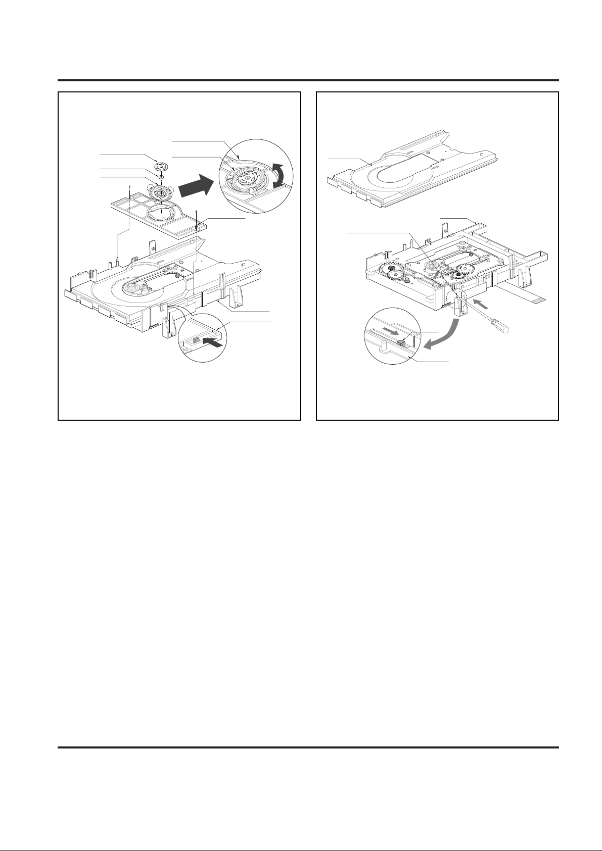
1.Holder Clamp (Fig. 4-1)
1) Release 2 Screws(S1).
2) Unhook 2 Locking Tabs(L1).
3) Lift up the Holder Clamp and then separate it from the
Base Main.
1-1. Clamp Assembly Disc
1) Place the Clamp Assembly Disc as Fig. (A)
2) Lift up the Clamp Assembly Disc in direction of
arrow(A).
3) Separate the Clamp Assembly Disc from the Holder
Clamp.
1-1-1. Plate Clamp
1) Turn the Plate Clamp to counterclockwise direction and
then lift up the Plate Clamp.
1-1-2. Magnet Clamp
1-1-3.Clamp Upper
2. Tray Disc (Fig. 4-2)
1) Insert and push a Driver in the emergency eject
hole(A) at the right side, or put the Driver on the
Lever(B) of the Gear Emergency and pull the Lever(B)
in direction of arrow so that the Tray Disc is ejected
about 15~20mm.
2) Pull the Tray Disc until it is separated from the Base
Main completely.
BASE MAIN
HOLDER CLAMP
HOLDER CLAMP
CLAMP ASSEMBLY DISC
HOLDER CLAMP
PLATE CLAMP
(S1)
(S1)
(A)
(L1)
(L1)
(Fig. A)
MAGNET CLAMP
CLAMP UPPER
(B)
LEVER
BOTTOM SIDE VIEW
EMERGENCY EJECT HOLE
(A)
TRAY DISC
BASE MAIN
BASE MAIN
Fig. 4-1 Fig. 4-2
4-3
DECK MECHANISM DISASSEMBLY
(L2)
(S2)
(C1)
(S2)
(S2)
(S2)
(S3)
GEAR ASSEMBLY RACK
PICK UP
ASSEMBLY
GENERAL
GEAR MIDDLE
GEAR ASSEMBLY FEED
BASE PU(OUTSERT)
RUBBER REAR
GEAR ASSEMBLY FEED
GEAR MIDDLE
GAER ASSEMBLY RACK
MOTOR ASSEMBLY SPINDLE
PICK UP ASSEMBLY GENERAL
MOTOR ASSEMBLY
SPINDLE
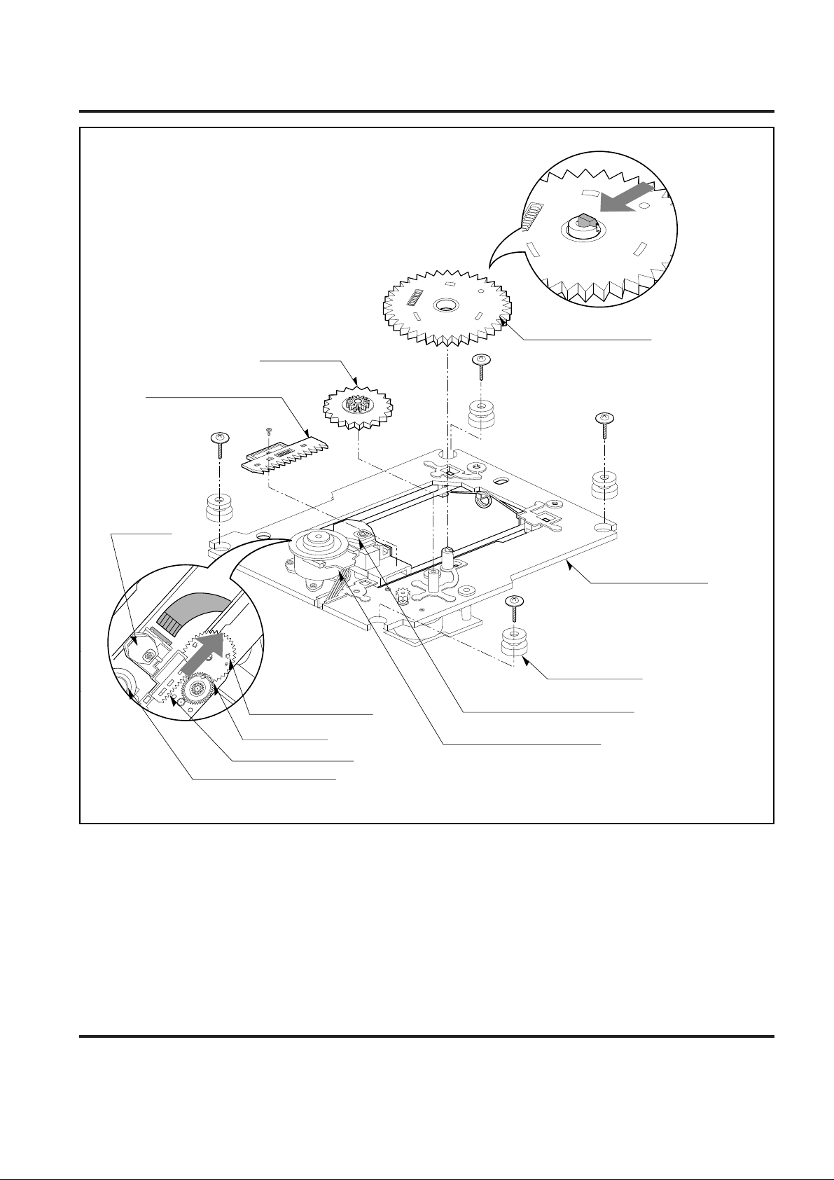
3.Base Assembly Sled (Fig. 4-3)
1) Release 4 Screw(S2).
2) Disconnect the FFC Connector(C1)
3-1. Gear Assembly Feed
1) Unhook the Locking Tab(L2) in direction of arrow.
3-2. Gear Middle
3-3. Gear Assembly Rack
1) Release the Scerw(S3)
4. Rubber Rear (Fig. 4-3)
Fig. 4-3
4-4
DECK MECHANISM DISASSEMBLY
(B)
(S5)
(L6)
(L4)
(L5)
(A)
(L3)
(A)
(L6)
(H1)
(C2)
(L6)
FIG. (B)
GUIDE UP/DOWN
BASE MAIN
BASE MAIN
PWB ASSEMBLY LOADING
GEAR LOADING
BELT LOADING
FRAME ASSEMBLY UP/DOWN
GUIDE UP/DOWN
GUIDE UP/DOWN
GUIDE UP/DOWN
(A)
(B)
(S4)
FIG. (C)
FIG. (A)
(B)
(C)
GEAR PULLEY
Fig. 4-4
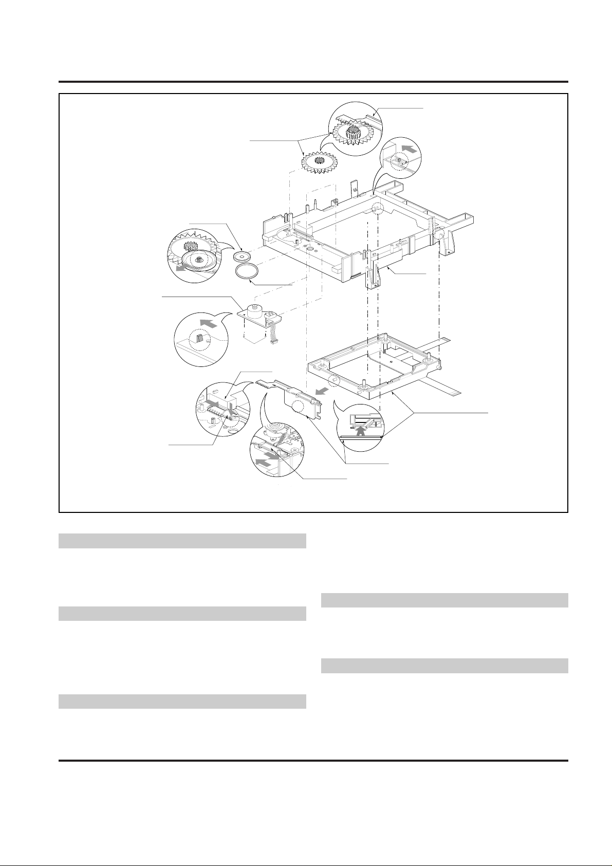
5. Frame Assembly Up/Down
Put the Base Main face down(Bottom Side)
1) Release the Screw(S4)
2) Unlock the Locking Tab(L3) in direction of arrow and
then lift up the Frame Assembly Up/Down to separate
it from the Base Main.
• When reassembling move the Guide Up/Down in direction
of arrow(C) until it is positioned as Fig.(C).
• When reassembling insert (A) portion of the Frame
Assembly Up/Down in the (B) portion of the Guide
Up/Down as Fig.(B)
6. Belt Loading(Fig. 4-4)
Put the Base Assembly Main on original position(Top Side)
7. Gear pulley (Fig. 4-4)
1) Unlock the Locking Tab(L4) in direction of arrow(B) and
then separate the Gear Pulley from the Base Main.
8. Gear Loading (Fig. 4-4)
9. Guide Up/Down (Fig. 4-4)
1) Move the Guide Up/Down in direction of arrow(A) as
Fig.(A)
2) Push the Locking Tab(L5) down and then lift up the
Guide Up/Down to separate it from the Base Main.
When reassembling place the Guide Up/Down as Fig.(C)
and move it in direction arrow(B) until it is locked by the
Locking Tab(L5). And confirm the Guide Up/Down as Fig.(A)
10. PWB Assembly Loading
Put the Base Main face down(Bottom Side)
1) Release 2 Screws(S5)
2) Unkool the Loading Motor Connector (C2) from the
Hook (H1) on the Base Main.
3) Unlock 2 Locking Tabs(L6) and separate the PWB
Assembly Loading from the Base Main.
11. Base Main(Fig. 4-4)
Note
Note
Note
Note
Note
4-5
DECK MECHANISM ADJUSTMENT
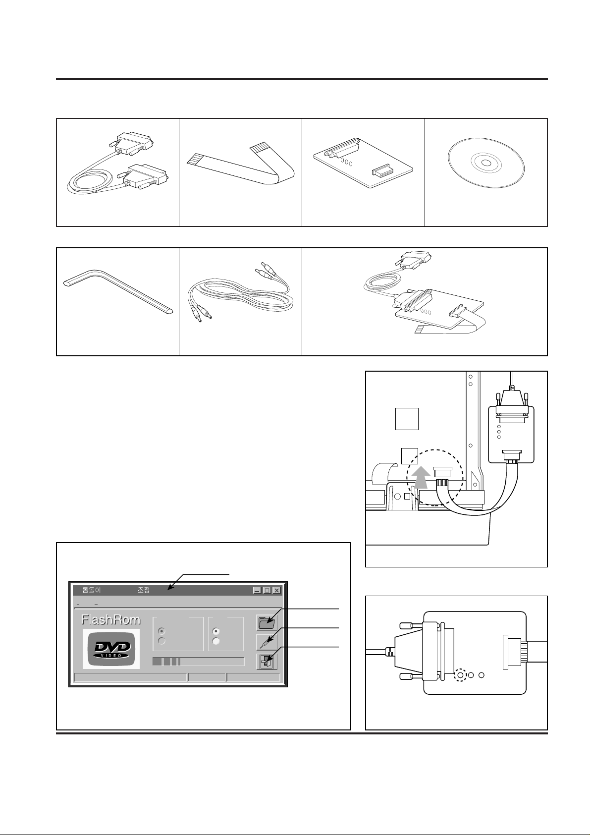
1. Tools and Fixtures for SVC
• For SVC Program Down-Load
• For T-Skew and R-Skew Adjustment
2. Install Process
1. Connect Fig. 1, 2, 3 as Fig. 7.
2. Plug out the Power cord of DVD set.
3. Connect FFC Cable(Fig.2) to the Connector on DVD Set(Fig.8)
4. Connect Printer Cable(Fig.1) to the P.C.Printer Port (LPT1).
5. Plug in the DVD Power cord.
6. Press the Menu key on Remocon.
7. Confirm No.1 LED(RED Color) of Jig board is ON. (Fig.9)
8. Perform The S/W for Down-load at P.C.
9. Open the Program File for Adjusting(Fig.10)
10. Click the Down-load Icon and perform Program Down-load.
11. Displayed remaining time.
12. Confirm LED No.1(RED) and No.2(GREEN) is ON.
13. Plug out the DVD Set Power cord.
14. Disconnect the FFC Cable.
Fig.1. Printer Cable Fig.2. FFC Cable (15 pin) Fig.3. Jig Board
Fig.4. Deviation Disc (0.8mm)
Fig.5. L-Wrench(3mm) Fig.6. RCA Jack Fig.7. Connecting Method
RED
GREEN
RED
Rom Size
File Help
16MBit
6M Bit
LPT1
Manual
953826Bytes
md _bas_ntsc.bin
LPT2
Port
FILE NAME
OPEN
DOWN LOAD
CLOSE
Fig.8. FFC Cable Connecting
Fig.9. Jig Board LED ConditionFig.10. Adjusting Program File Open
MEMO
4-6
DECK MECHANISM ADJUSTMENT
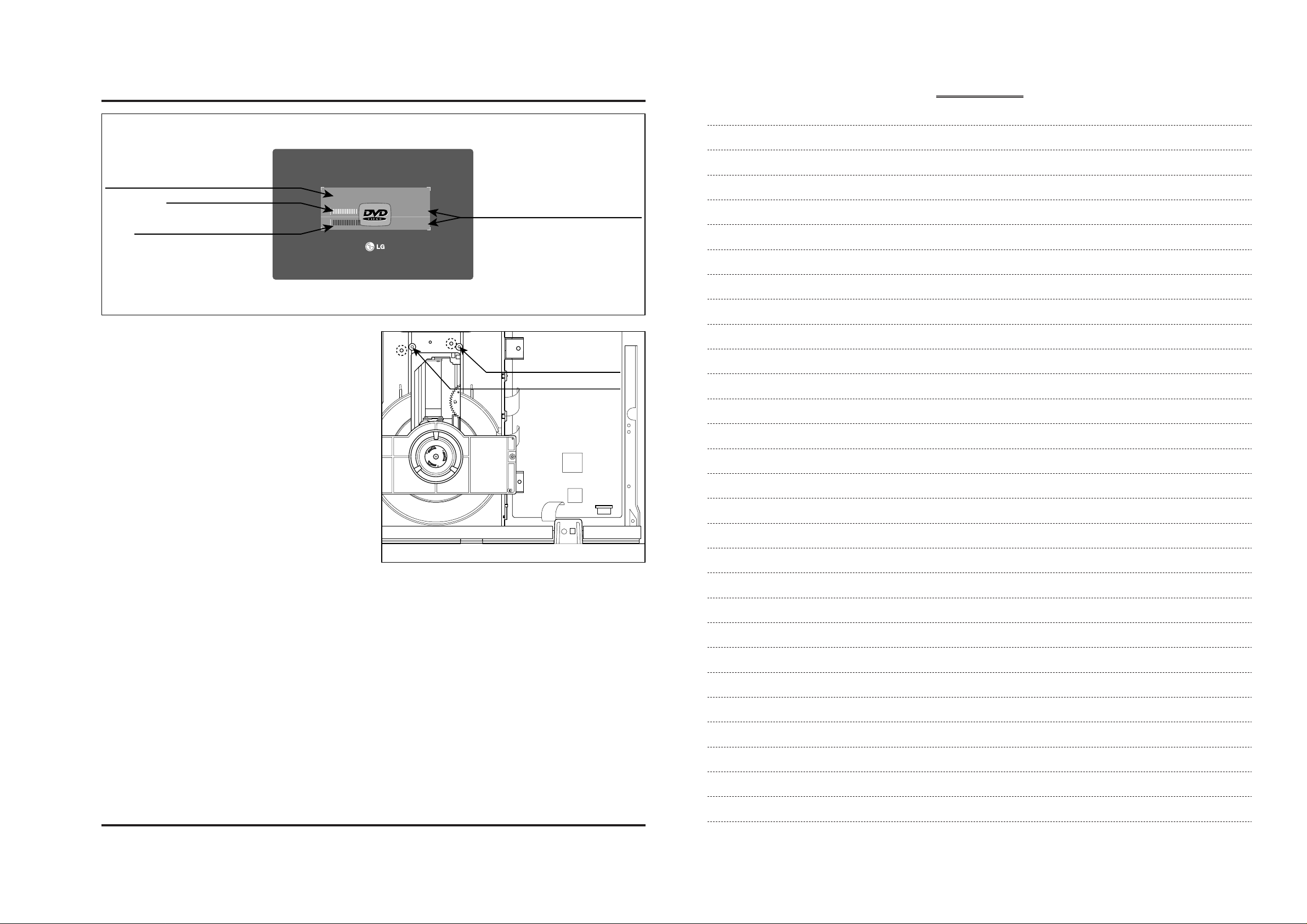
3. Adjustment Procedure
1. Insert Disc(Only Open/Close Key Pressing)
2. Wait Until the Sector Display is about 200,000 (Fig.11)
3. Adjust R-Skew adjusting Point until the Error rate has
Minimum rate with L-wrench (3mm).
4. Adjust T-Skew Adjusting Point until the Error rate has
Minimum rate.
5. Repeat No. 3, 4 adjusting procedure until the Error rate
have Minimum rate.
6. Error rate; SVC-3561 Disc=below 30 and TDV-533
Disc=below 100. If not, Please confirm Play ability on
screen.
# You can watch the screen when pressing the Stop key
after the Adjusting is finished, Then perform Play and
Scan/Skip operation at Chapter1 and Chapter16 and
confirm screen condition, normal or abnormal.
• Please obtain these software for Adjusting through our
Global Cyber Service Center(GCSC).
• The location is http://biz.lgservice.com
& Web Site for End users
& Software updates
& Product : DVD Player
& Search.
R-SKEW ADJUSTING HOLE
T-SKEW ADJUSTING HOLE
Fig.12. Adjusting Method
Fig.11. Adjusting Screen Display
0045
SECTOR : 200145
0065
CURRENT PICK UP POSITION
ERROR RATE SIZE
ERROR RATE (HEXADEAMAL)
AVERAGE ERROR RATE
4-7 4-8
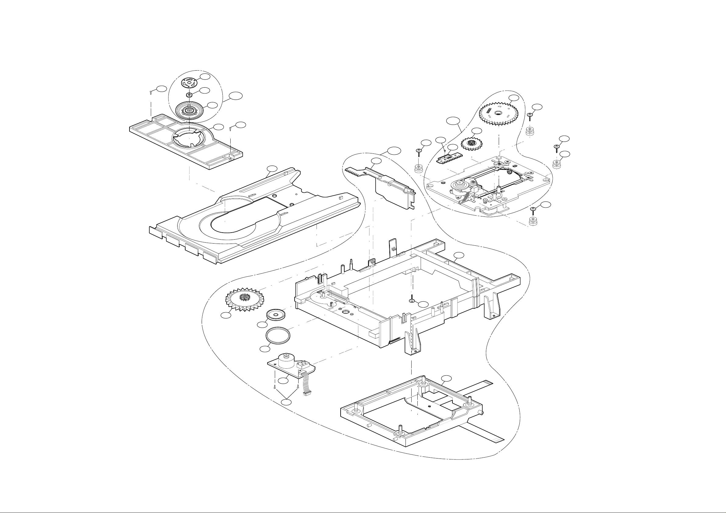
EXPLODED VIEWS
1. Deck Mechanism Exploded View
002
001
003
004
429
429
026
018
008
009
016
012
430
430
430
430
432
020
430
011
017
014
013
015
431
A01
A02
A03
1-3
CAUTION : DO NOT ATTEMPT TO MODIFY THIS PRODUCT IN ANY WAY,
NEVER PERFORM CUSTOMIZED INSTALLATIONS WITHOUT MANUFACTURER’S APPROVAL. UNAUTHORIZED MODIFICATIONS WILLNOT ONLY
VOID THE W ARRANTY, BUT MAYLEAD TO YOUR BEING LIABLE FOR ANY
RESULTING PROPERTYDAMAGE OR USER INJURY.
SERVICE WORK SHOULD BE PERFORMED ONLY AFTER YOU ARE
THOROUGHLY FAMILIAR WITH ALL OF THE FOLLOWING SAFETY
CHECKS AND SERVICING GUIDELINES. TO DO OTHERWISE,
INCREASES THE RISK OF POTENTIAL HAZARDS AND INJURY TO THE
USER.
WHILE SERVICING, USE AN ISOLATION TRANSFORMER FOR PROTECTION FROM A.C. LINE SHOCK.
SAFETY CHECKS
AFTER THE ORIGINAL SERVICE PROBLEM HAS BEEN CORRECTED. A
CHECK SHOULD BE MADE OF THE FOLLOWING.
SUBJECT : FIRE & SHOCK HAZARD
1. BE SURE THATALL COMPONENTS ARE POSITIONED IN SUCH A WAY
AS TO AVOID POSSIBILITY OF ADJACENT COMPONENT SHORTS.
THIS IS ESPECIALLY IMPORTANT ON THOSE MODULES WHICH ARE
TRANSPORTED TO AND FROM THE REPAIR SHOP.
2. NEVER RELEASE A REPAIR UNLESS ALL PROTECTIVE DEVICES
SUCH AS INSULATORS, BARRIERS, COVERS, SHIELDS, STRAIN
RELIEFS, POWER SUPPLY CORDS, AND OTHER HARDWARE HAVE
BEEN REINSTALLED PER ORIGINAL DESIGN. BE SURE THAT THE
SAFETY PURPOSE OF THE POLARIZED LINE PLUG HAS NOT BEEN
DEFEATED.
3. SOLDERING MUST BE INSPECTED TO DISCOVER POSSIBLE COLD
SOLDER JOINTS, SOLDER SPLASHES OR SHARP SOLDER POINTS.
BE CERTAIN TO REMOVE ALLLOOSE FOREIGN PARTICLES.
4. CHECK FOR PHYSICAL EVIDENCE OF DAMAGE OR DETERIORATION
TO PARTS AND COMPONENTS, FOR FRAYED LEADS, DAMAGED
INSULATION (INCLUDING A.C. CORD), AND REPLACE IF NECESSARY.
FOLLOW ORIGINAL LAYOUT, LEAD LENGTH AND DRESS.
5. NO LEAD OR COMPONENT SHOULD TOUCH A RECIVING TUBE OR
A RESISTOR RATED AT 1 WATT OR MORE. LEAD TENSION AROUND
PROTRUDING METALSURFACES MUST BE AVOIDED.
6. ALL CRITICAL COMPONENTS SUCH AS FUSES, FLAMEPROOF
RESISTORS, CAPACITORS, ETC. MUST BE REPLACED WITH EXACT
FACTORY TYPES, DO NOT USE REPLACEMENT COMPONENTS
OTHER THAN THOSE SPECIFIED OR MAKE UNRECOMMENDED CIRCUIT MODIFICATIONS.
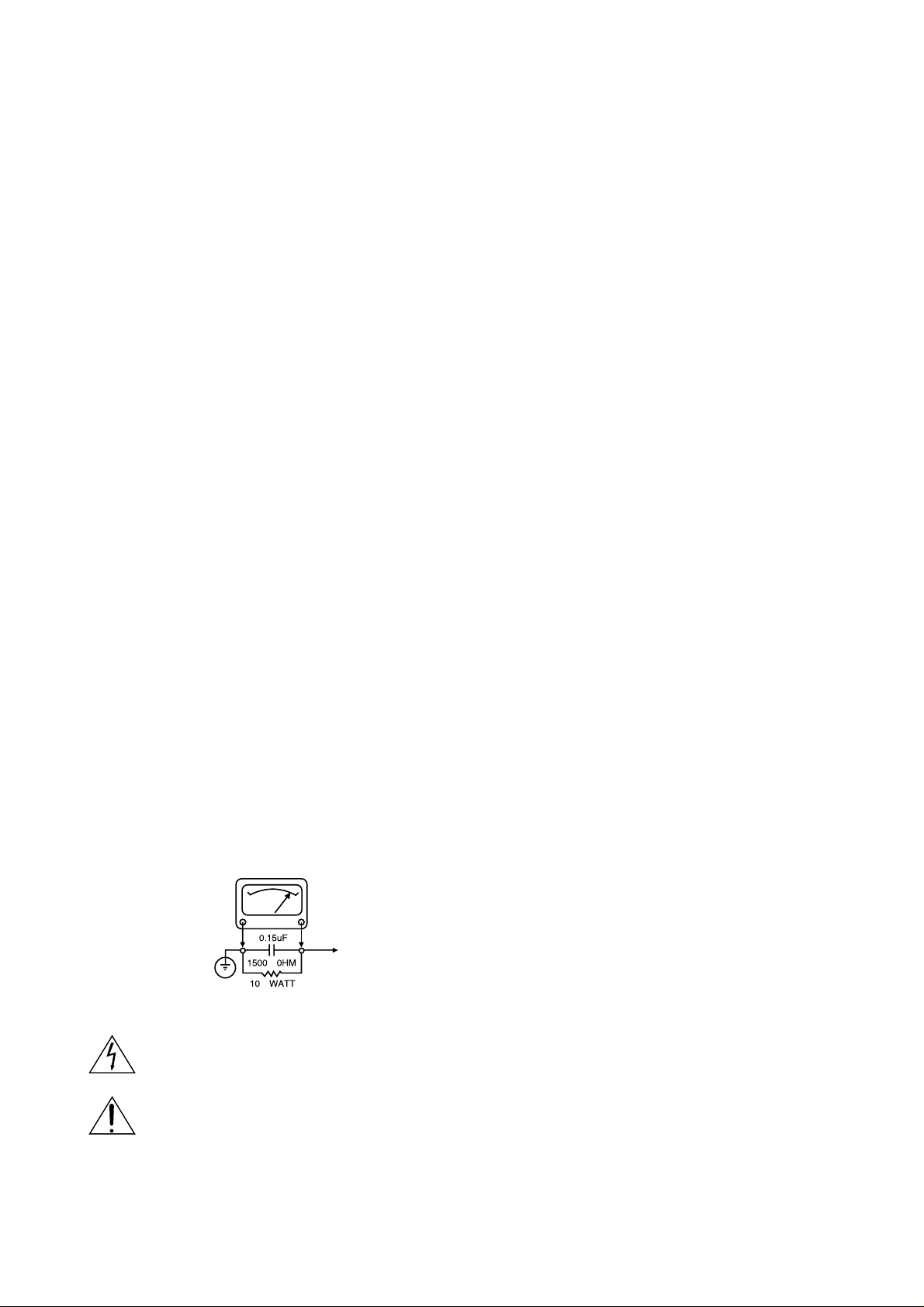
7. AFTER RE-ASSEMBLY OF THE SET ALWAYS PERFORM AN A.C.
LEAKAGE TEST ON ALL EXPOSED METALLIC PARTS OF THE CABINET, (THE CHANNEL SELECTOR KNOB, ANTENNATERMINALS. HANDLE AND SCREWS) TO BE SURE THE SET IS SAFE TO OPERATE
WITHOUT DANGER OF ELECTRICAL SHOCK. DO NOT USE A LINE
ISOLATION TRANSFORMER DURING THIS TEST USE AN A.C. VOLTMETER, HAVING 5000 OHMS PER VOLT OR MORE SENSITIVITY, IN
THE FOLLOWING MANNER; CONNECT A 1500 OHM 10 WATT RESISTOR, PARALLELED BY A .15 MFD. 150.V A.C TYPE CAPACITOR
BETWEEN A KNOWN GOOD EARTH GROUND (WATER PIPE, CONDUIT, ETC.) AND THE EXPOSED METALLIC PARTS, ONE AT A TIME.
MEASURE THE A.C. VOLTAGE ACROSS THE COMBINATION OF 1500
OHM RESISTOR AND .15 MFD CAPACITOR. REVERSE THE A.C. PLUG
AND REPEAT A.C. VOLTAGE MEASUREMENTS FOR EACH EXPOSED
METALLIC PART. VOLTAGE MEASURED MUST NOT EXCEED 75
VOLTS R.M.S. THIS CORRESPONDS TO 0.5 MILLIAMP A.C ANY
VALUE EXCEEDING THIS LIMIT CONSTITUTES A POTENTIAL SHOCK
HAZARD AND MUST BE CORRECTED IMMEDIATELY.
SUBJECT: GRAPHIC SYMBOLS
THE LIGHTNING FLASH WITH APROWHEAD SYMBOL. WITHIN
AN EQUILATERAL TRIANGLE, IS INTENDED TO ALERT THE
SERVICE PERSONNEL TO THE PRESENCE OF UNINSULATED
“DANGEROUS VOLTAGE” THAT MAY BE OF SUFFICIENT MAGNITUDE TO CONSTITUTE A RISK OF ELECTRIC SHOCK.
THE EXCLAMATION POINT WITHIN AN EQUILATERAL TRIANGLE IS INTENDED TO ALERT THE SERVICE PERSONNEL TO
THE PRESENCE OF IMPORTANT SAFETY INFORMATION IN
SERVICE LITERATURE.
SUBJECT : X-RADIATION
1. BE SURE PROCEDURES AND INSTRUCTIONS TO ALL SERVICE PERSONNEL COVER THE SUBJECT OF X-RADIATION. THE ONLY POTENTIAL SOURCE OF X-RAYS IN CURRENT T.V. RECEIVERS IS THE PICTURE TUBE. HOWEVER, THIS TUBE DOES NOT EMIT X-RAYS WHEN
THE HIGH VOLTAGE IS AT THE FACTORY SPECIFIED LEVEL. THE
PROPER VALUE IS GIVEN IN THE APPLICABLE SCHEMATIC. OPERATION AT HIGHER VOLTAGES MAY CAUSE A FAILURE OF THE PICTURE TUBE OR HIGH VOLTAGE SUPPLY AND, UNDER CERTAIN CIRCUMSTANCES, MAY PRODUCE RADIATION IN EXCESS OF DESIRABLE LEVELS.
2. ONLY FACTORY SPECIFIED C.R.T. ANODE CONNECTORS MUST BE
USED. DEGAUSSING SHIELDS ALSO SERVE AS AN X-RAY SHIELD IN
COLOR SETS, ALWAYS RE-INSTALLTHEM.
3. IT IS ESSNTIAL THAT SERVICE PERSONNEL HAVE AVAILABLE AN
ACCURATE AND RELIABLE HIGH VOLTAGE METER. THE CALIBRATION OF THE METER SHOULD BE CHECKED PERIODICALLY
AGAINST A REFERENCE STANDARD, SUCH AS THE ONE AVAILABLE
ATYOUR DISTRIBUTOR.
4. WHEN THE HIGH VOLTAGE CIRCUITRY IS OPERATING PROPERLY
THERE IS NO POSSIBILITY OF AN X-RADIATION PROBLEM. EVERY
TIME A COLOR CHASSIS IS SERVICED. THE BRIGHTNESS SHOULD
BE RUN UP AND DOWN WHILE MONITORING THE HIGH VOLTAGE
WITH A METER TO BE CERTAIN THAT THE HIGH VOLTAGE DOES
NOT EXCEED THE SPECIFIED VALUE AND THAT IT IS REGULATING
CORRECTLY. WE SUGGEST THAT YOU AND YOUR SERVICE ORGANIZATION REVIEW TEST PROCEDURES SO THAT VOLTAGE REGULATION IS ALWAYS CHECKED AS A STANDARD SERVICING PROCEDURE AND THAT THE HIGH VOLTAGE READING BE RECORDED ON
EACH CUSTOMER’S INVOICE.
5. WHEN TROUBLESHOOTING AND MAKING TEST MEASUREMENTS IN
A PRODUCT WITH A PROBLEM OF EXCESSIVE HIGH VOLTAGE,
AVOID BEING UNNECESSARILY CLOSE TO THE PICTURE TUBE AND
THE HIGH VOLTAGE SUPPLY. DO NOT OPERATE THE PRODUCT
LONGER THAN IT IS NECESSARYTO LOCATE THE CAUSE OF EXCESSIVE VOLTAGE.
6. REFER TO HV. B+ AND SHUTDOWN ADJUSTMENT PROCEDURES
DESCRIBED IN THE APPROPRIATE SCHEMATIC AND DIAGRAMS
(WHERE USED).
SUBJECT: IMPLOSION
1. ALL DIRECT VIEWED PICTURE TUBES ARE EQUIPPED WITH AN INTEGRAL IMPLOSION PROTECTION SYSTEM, BUT CARE SHOULD BE
TAKEN TO AVOID DAMAGE DURING INSTALLATION, AVOID
SCRATCHING THE TUBE. IF SCRATCHED REPLACE IT.
2. USE ONLY RECOMMENDED FACTORY REPLACEMENT TUBES.
SUBJECT : TIPS ON PROPER INSTALLATION
1. NEVER INSTALL ANY PRODUCT IN A CLOSED-IN RECESS, CUBBYHOLE OR CLOSELY FITTING SHELF SPACE, OVER OR CLOSE TO
HEAT DUCT, OR IN THE PATH OF HEATED AIR FLOW.
2. AVOID CONDITIONS OF HIGH HUMIDITY SUCH AS: OUTDOOR PATIO
INSTALLATIONS WHERE DEW IS A FACTOR, NEAR STEAM RADIATORS WHERE STEAM LEAKAGE IS AFACTOR, ETC.
3. AVOID PLACEMENT WHERE DRAPERIES MAY OBSTRUCT REAR
VENTING. THE CUSTOMER SHOULD ALSO AVOID THE USE OF DECORATIVE SCARVES OR OTHER COVERINGS WHICH MIGHT
OBSTRUCT VENTILATION.
4. WALL AND SHELF MOUNTED INSTALLATIONS USING A COMMERCIAL MOUNTING KIT, MUST FOLLOW THE FACTORY APPROVED
MOUNTING INSTRUCTIONS. A PRODUCT MOUNTED TO A SHELF OR
PLATFORM MUST RETAIN ITS ORIGINAL FEET (OR THE EQUIVALENT
THICKNESS IN SPACERS) TO PROVIDE ADEQUATE AIR FLOW
ACROSS THE BOTTOM. BOLTS OR SCREWS USED FOR FASTENERS
MUST NOT TOUCH ANY PARTS OR WIRING. PERFORM LEAKAGE
TEST ON CUSTOMIZED INSTALLATIONS.
5. CAUTION CUSTOMERS AGAINST THE MOUNTING OF A PRODUCT ON
SLOPING SHELF OR A TILTED POSITION, UNLESS THE PRODUCT IS
PROPERLY SECURED.
6. A PRODUCT ON A ROLL-ABOUT CART SHOULD BE STABLE ON ITS
MOUNTING TO THE CART. CAUTION THE CUSTOMER ON THE HAZARDS OF TRYING TO ROLLA CART WITH SMALL CASTERS ACROSS
THRESHOLDS OR DEEP PILE CARPETS.
7. CAUTION CUSTOMERS AGAINST THE USE OF A CART OR STAND
WHICH HAS NOT BEEN LISTED BY UNDERWRITERS LABORATORIES,
INC. FOR USE WITH THEIR SPECIFIC MODEL OF TELEVISION
RECEIVER OR GENERICALLY APPROVED FOR USE WITH T.V.’S OF
THE SAME OR LARGER SCREEN SIZE.
8. CAUTION CUSTOMERS AGAINST THE USE OF EXTENSION CORDS.
EXPLAIN THAT A FOREST OF EXTENSIONS SPROUTING FROM ASINGLE OUTLET CAN LEAD TO DISASTROUS CONSEQUENCES TO
HOME AND FAMILY.
PRODUCT SAFETY SERVICING GUIDELINES FOR VIDEO PRODUCTS
A.C. VOLTMETER
GOOD EARTH GROUND
SUCH AS THE WATER
PIPE. CONDUIT. ETC
PLACE THIS PROBE
ON EACH EXPOSED
METALPART

1-4
SERVICING PRECAUTIONS
CAUTION : Before servicing the DVD covered by this service
data and its supplements and ADDENDUMS, read and follow the
SAFETY PRECAUTIONS. NOTE
: if unforeseen circumstances create conflict between the following servicing
precautions and any of the safety precautions in this publications, always follow the safety precautions.
Remember Safety First:
General Servicing Precautions
1. Always unplug the DVD AC power cord from the AC
power source before:
(1)Removing or reinstalling any component, circuit board,
module, or any other assembly.
(2)Disconnection or reconnecting any internal electrical
plug or other electrical connection.
(3)Connecting a test substitute in parallel with an elec-
trolytic capacitor.
Caution : A wrong part substitution or incorrect
polarity installation of electrolytic capacitors may result
in an explosion hazard.
2. Do not spray chemicals on or near this DVD or any of
its assemblies.
3. Unless specified otherwise in this service data, clean
electrical contacts by applying an appropriate contact
cleaning solution to the contacts with a pipe cleaner,
cotton-tipped swab, or comparable soft applicator.
Unless specified otherwise in this service data, lubrication
of contacts is not required.
4. Do not defeat any plug/socket B+ voltage interlocks with
whitch instruments covered by this service manual might
be equipped.
5. Do not apply AC power to this DVD and/or any of its
electrical assemblies unless all solid-state device heat
sinks are cerrectly installed.
6. Always connect test instrument ground lead to the
appropriate ground before connection the test instrument
positive lead. Always remove the test instrument ground
lead last.
Insulation Checking Procedure
Disconnect the attachment plug from the AC outlet and turn
the power on. Connect an insulation resistance meter(500V)
to the blades of the attachment plug. The insulation resistance between each blade of the attachment plug and accessible conductive parts (Note 1) should be more than 1Mohm.
Note 1 : Accessible Conductive Parts including Metal panels, Input terminals, Earphone jacks, etc.
Electrostatically Sensitive (ES) Devices
Some semiconductor (solid state) devices can be damaged
easily by static electricity. Such components commonly are
called Electrostatically Sensitive (ES) Devices. Examples of
typical ES devices are integrated circuits and some field
effect transistors and semiconductor chip components.
The following techniques should be used to help reduce the
incidence of component damage caused by static electricity.
1. Immediately before handling any semiconductor component or semiconductor-equipped assembly, drain off any
electrostatic charge on your body by touching a known
earth ground. Alternatively, obtain and wear a commercially available discharging wrist strap device, which
should be removed for potential shock reasons prior to
applying power to the unit under test.
2. After removing an electrical assembly equipped with ES
devices, place the assembly on a conductive surface such
as aluminum foil, to prevent electrostatic charge buildup or
exposure of the assembly.
3. Use only a GROUNDED-tip soldering iron to solder or
unsolder ES devices.
4. Use only an anti-static solder removal device. Some
solder removal devices not classified a “anti-static” can
generate electrical charges sufficient to damage ES
devices.
5. Do not use freon-propelled chemicals. These can
generate electrical charge sufficient to damage ES
devices.
6. Do not remove a replacement ES device from its protec
tive package until immediately before you are ready to
install it. (Most replacement ES devices are packaged with
leads electrically shorted together by conductive foam,
aluminum foil, or comparable conductive material).
7. Immediately before removing the protective material from
the leads of a replacement ES device, touch the protective
material to the chassis or circuit assembly into which the
device will be installed.
Caution : Be sure no power is applied to the chassis or
circuit, and observe all other safety precautions.
8. Minimize bodily motions when handling unpackaged
replacement ES devices. (Normally harmless motion such
as the brushing together of your clothes fabric or the lifting
of your foot from a carpeted floor can generate static electricity sufficient to damage an ES device.)
2-2
DISASSEMBLY
CAUTION BEFORE STARTING SERVICING
Electronic parts are susceptible to static electricity and may easily damaged, so do not forget to take a
proper grounding treatment as required.
Many screws are used inside the unit. To prevent missing, dropping, etc. of the screws, always use a
magnetized screw driver in servicing. Several kinds of screws are used and some of them need special
cautions. That is, take care of the tapping screws securing molded patrs and fine pitch screws used to secure
metal parts. If they are used improperly , the screw holes will be easily damaged and the parts can not be fixed.
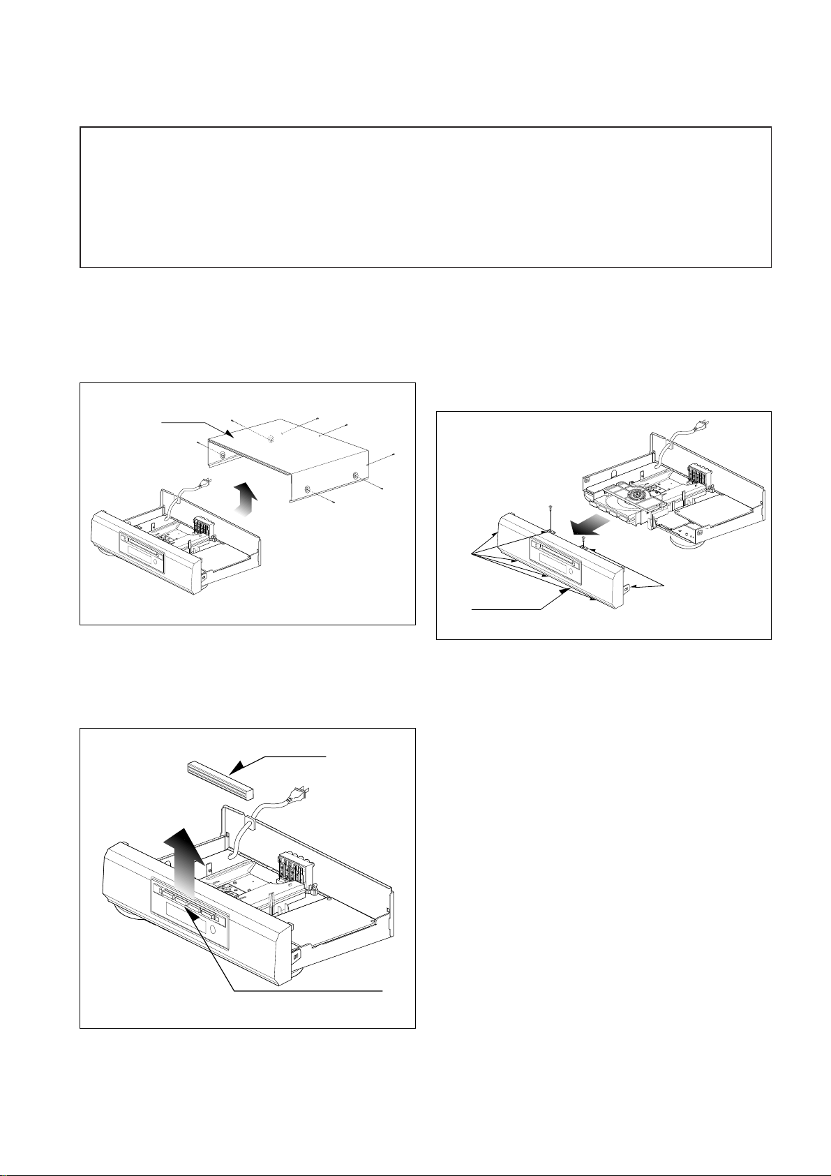
Top Case
(A)
(A)
(A)
(A)
(A)
(A)
(A)
Tray Door
Disc Tray
Front Panel
Stopper
Stopper
(B)
(B)
CABINET DISASSEMBLY
1. Top Case
1. Release 7 screws (A). (See Fig. 2-1)
2. Lift the top case with holding the back of it,
and remove it in the direction of the arrow
Fig. 2-1
Fig. 2-2
Fig. 2-3
3. Front Panel
1. Eject the disc tray. (See Fig. 2-2)
2. Remove the tray door. (See Fig. 2-2)
3. Release 2 screws (B).
4. Pull the front panel toward you while pressing
7 stoppers to disengage, and remove the front
panel. (See Fig. 2-3)
2.Tray Door
1.Eject the disc tray.
2. Lift up the tray door in the direction of the
arrow.
2-3
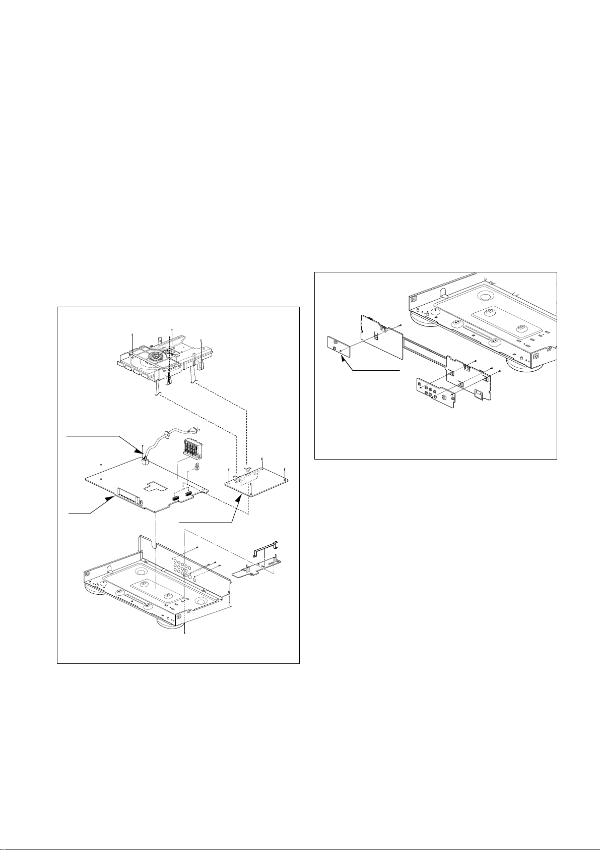
Main Circuit Board
(C)
(C)
(C)
(C)
(C)
(C)
(C)
(C)
(C)
(C)
(C)
(C)
Power Code
Interface
Board
(D)
(D)
Key
Circuit Board
(E)
(E)
(E)
(E)
Fig. 2-4
Fig. 2-5
1. Disassembling of Main Circuit Board
and Interface Board
1. Remove the top case.(See Fig. 2-1)
2. Remove 12 screw (C).
3. Remove the deck from Main Circuit Board.
4. Remove Main Circuit Board from Interface Board.
5. Remove 2 screw (D).
6. Remove Interface Board from the chassis.
CIRCUIT BOARD DISASSEMBLY
Note: Before removing the main circuit board, be sure to shortcircuit the laserdiode output land.
After replacing the main circuit board, open the land after inserting the flexible connector.
(Refer to Mechanism Disassembly)
2. Digitron and Key Circuit Board
1. Remove the front panel.(See Fig. 2-3)
2. Release 4 screws (E), and remove the digitron
circuit board.
 Loading...