

LG DRD-8080B Service Manual

3
INTRODUCTION
GENERAL FEATURE
SPECIFICATIONS
1. SUPPORTED SYSTEM
• IBM Compatible Pentium 133MHz or Above (with PIO mode 4, TX chip set recommended)
2. SUPPORTED OS
3. GENERAL PERFORMANCE
• Data Transfer Rate ...........................................................................................Sustained Data Transfer Rate
DVD (Outer side) : Approx. 10,800 kbytes/sec
DVD (Inner side) : Approx. 4,725 kbytes/sec
CD (Outer side) : Approx. 6,000 kbytes/sec
CD (Inner side) : Approx. 2,625 kbytes/sec
• Data Buffer Capacity.......................................................................................................................512 kbytes
• Access Time...................................................................Random Access DVD : 120ms Typical (8X)
CD : 100ms Typical (40X)
4. POWER REQUIREMENTS
• Voltage ........................................................................................................................................+5V DC +5%
+12V DC +5%
• Ripple .....................................................................................................................................+5V : 100mVp-p
+12V : 100mVp-p
• Current .........................................................................................+12V : 400mA (Average), 0.9A (Maximum)
+5V : 500mA (Average), 1.2A (Maximum)
5. AUDIO PERFORMANCE
• Frequency Response......................................................................................................20Hz~20KHz(+ 3dB)
• S/N Ratio (IHF-A+20kHZ LPF) ..........................................................................88 dB (Typical at 1 KHz 0dB)
80 dB (Limit at 1 KHz 0dB)
• T.H.D. (IHF-A+20kHZ LPF)...............................................................................0.05% (Typical at 1 KHz 0dB)
0.15% (Limit at 1 KHz 0dB)
• Channel Separation (IHF-A+20kHZ LPF) .................................................................................75 dB(Typical)
70 dB(Limit)
• Output Voltage (1kHz 0dB) 47KΩ Load ..................................................................................0.8Vrms +20%
• Headphone Level (1kHz 0dB) 33Ω Load.................................................................................0.8Vrms +20%
• Enhanced IDE interface
• Internal 5.25 inch, halfheight DVD-ROM Drive
• 120ms (Typical) Random Access Time (DVD)
• 100ms (Typical) Random Access Time (CD)
• Supports 8X (max) Rotational Modes in DVD Mode
• Supports 40X (max) Rotational Modes in CD Mode
• Max 10,800 kB/sec Sustained Transfer rate in DVD mode
• Max 6,000 kB/sec Sustained Transfer rate in CD mode
• Photo-CD Multisession Disc Spec compliant
• Multimedia MPC-3 Spec compliant
• Power Tray Loading/Ejection Mechanism
• 3-Way Eject Support (Software, Open/Close Button,
Emergency Eject)
• Closed Enclosure
• Built-in ATAPI Interface Controller
• Software Volume Control
• Easy CD-Audio Play front panel Controls
• Front panel Volume Control for Headphone Output
• Built-in MODE-1 ECC/EDC
• MTBF (125,000H) POH (at 10% Utilization)
• PIO Mode 4 & Multiword DMA Mode 2 Support
• ULTRA DMA 33 support
• Horizontal/Vertical Mounting
• Digital audio output connector
• Digital audio through ATAPI Interface
• Spin-down Mode for energy saving
• MS-DOS (Ver 3.1 or Higher)
• Windows 3.1/95/98/2000
• Windows NT (Ver 4.0)
• OS/2 Warp (Ver 3.0)
• Solaris (Ver 2.4 or Higher)
• Linux ’96 Slacware (Ver 3.1.0)
This service manual provides a variety of service
information. It contains the mechanical structure of
the DVD-ROM Drive together with mechanical
adjustments and the electronic circuits in schematic
form. This DVD-ROM Drive was manufactured and
assembled under our strict quality control standards
and meets or exceeds industry specifications and
standards.
4
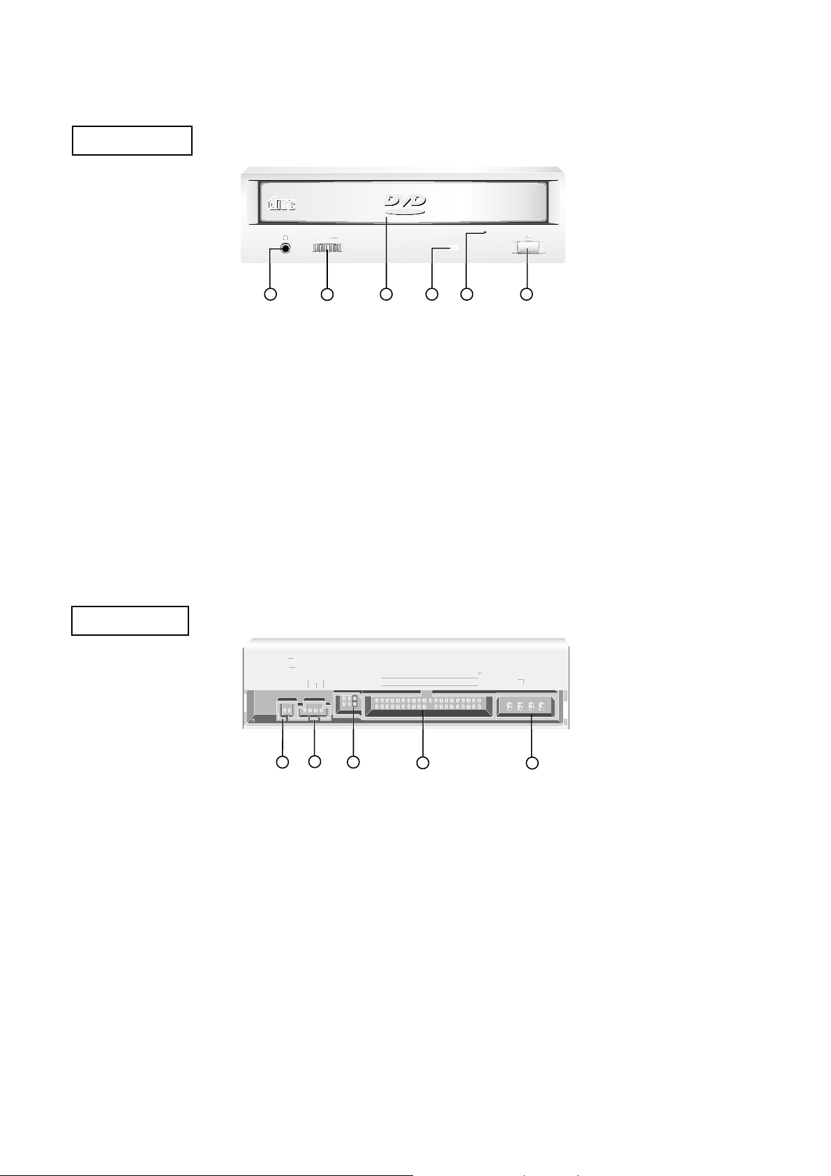
LOCATION OF CUSTOMER CONTROLS
(1) Digital Audio Ouput Connector
This is a digital audio output or Video CD output
connector.
You can connect this to a digital audio system or a
Video CD Board.
(2) Analog Audio Output Connector
The Audio Output Connector connects to a sound
card.
(3) Master/Slave/CSEL Jumper
These three jumpers are used to set the DVD-ROM
Drive to either a Master, Slave, or CSEL device.
(4) Interface Connector
This 40-pin connector is used to transfer data and
control signals between the DVD-ROM Drive and your
PC.
(5) Power-in Connector
Attach a power cable from the computer to this
connector.
COMPACT
COMPACT
1
2
43
ROM
ROM
ROM
ROM
5 6
DIGITAL ANALOG
INTERFACE POWER
DR CSM
SLA
GLG39
1
+5
+12
GND
40
2
AUDIO AUDIO
1
2
5
4
3
FRONT VIEW
BACK VIEW
(1) Headphone Jack
Standard
1
/
8
″
(3.5mm) stereo jack for listening to the
audio signal from audio CDs.
(2) Headphone Volume Control
Adjusts the headphone sound level.
(3) Disc Drawer
Accepts a CD-ROM/DVD-ROM disc on its tray.
(4) Busy Indicator
The Busy Indicator lights during initialization and dataread operations.
(5) Emergency Eject Hole
Insert a paper clip here to eject the drawer manually or
when there is no power.
(6) Open/Close/Stop Button
This button is pressed to open or close the CD tray.
If an audio CD is playing, pressing this button will stop
it, and pressing it again will open the tray.
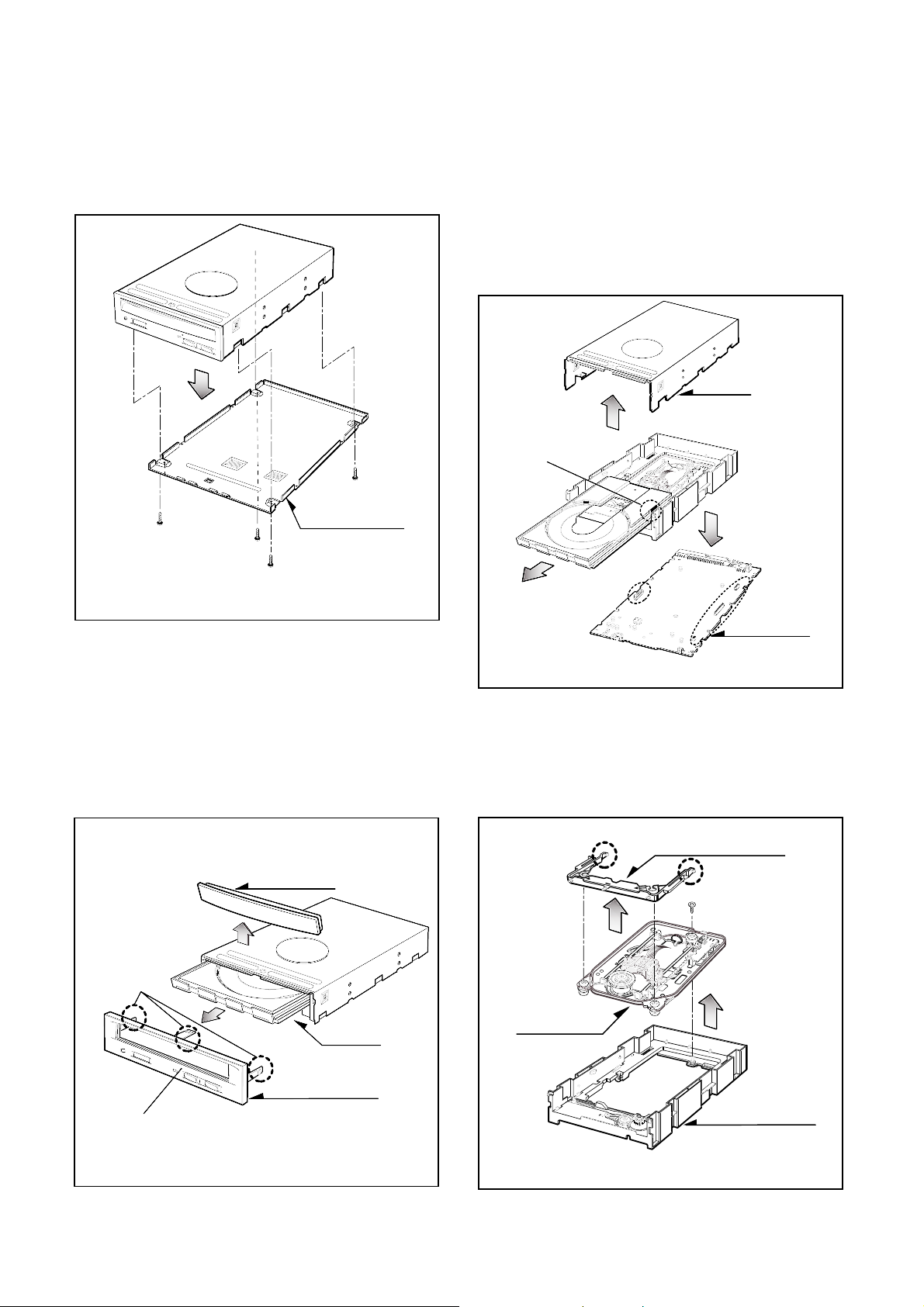
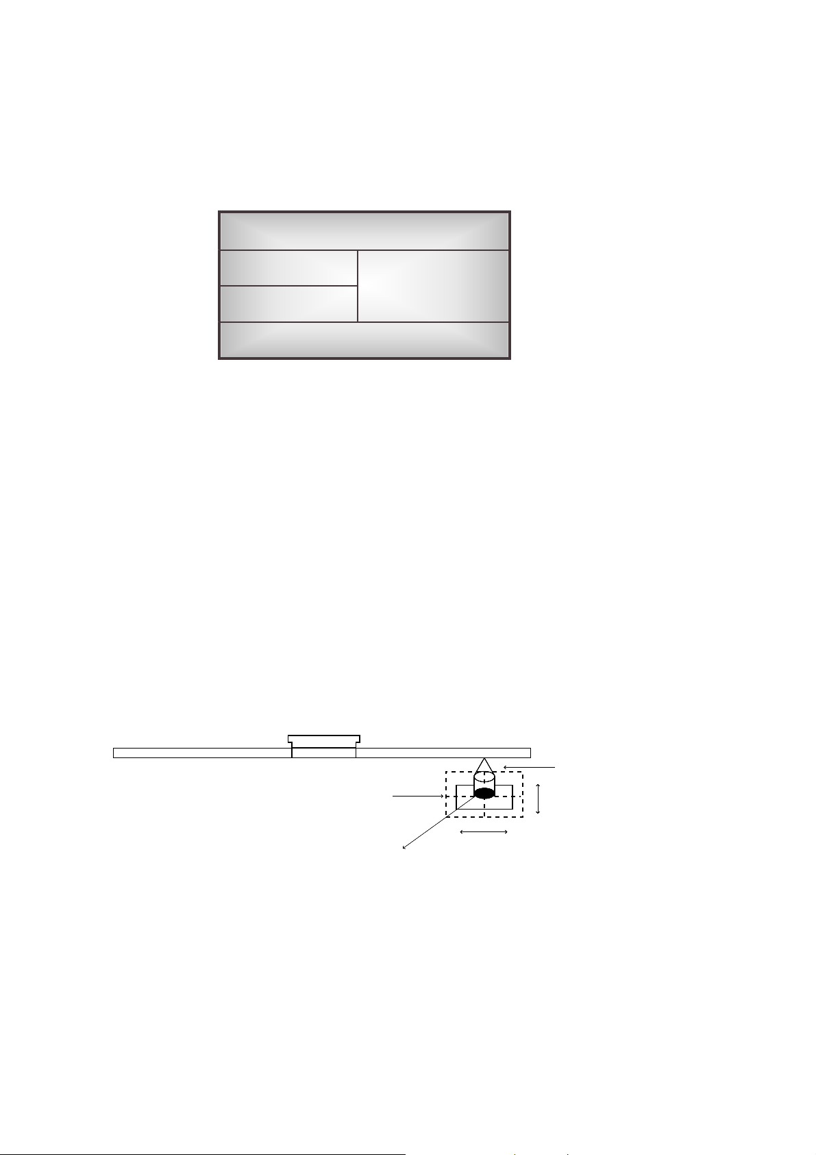
1. CABINET and CIRCUIT BOARD
DISASSEMBLY
1-1. Bottom Mecha
A. Release 4 screws (A) and remove the Bottom Mecha
in the direction of arrow (1). (See Fig.1-1)
1-2. Front Bezel Assy
A. Insert and press a rod in the Emergency Eject
Hole and then the CD Tray will open in the direction
of arrow (2).
B. Remove the Tray Door in the direction of arrow
(3) by pushing the stoppers forward.
C. Release 3 stoppers and remove the Front Bezel Assy.
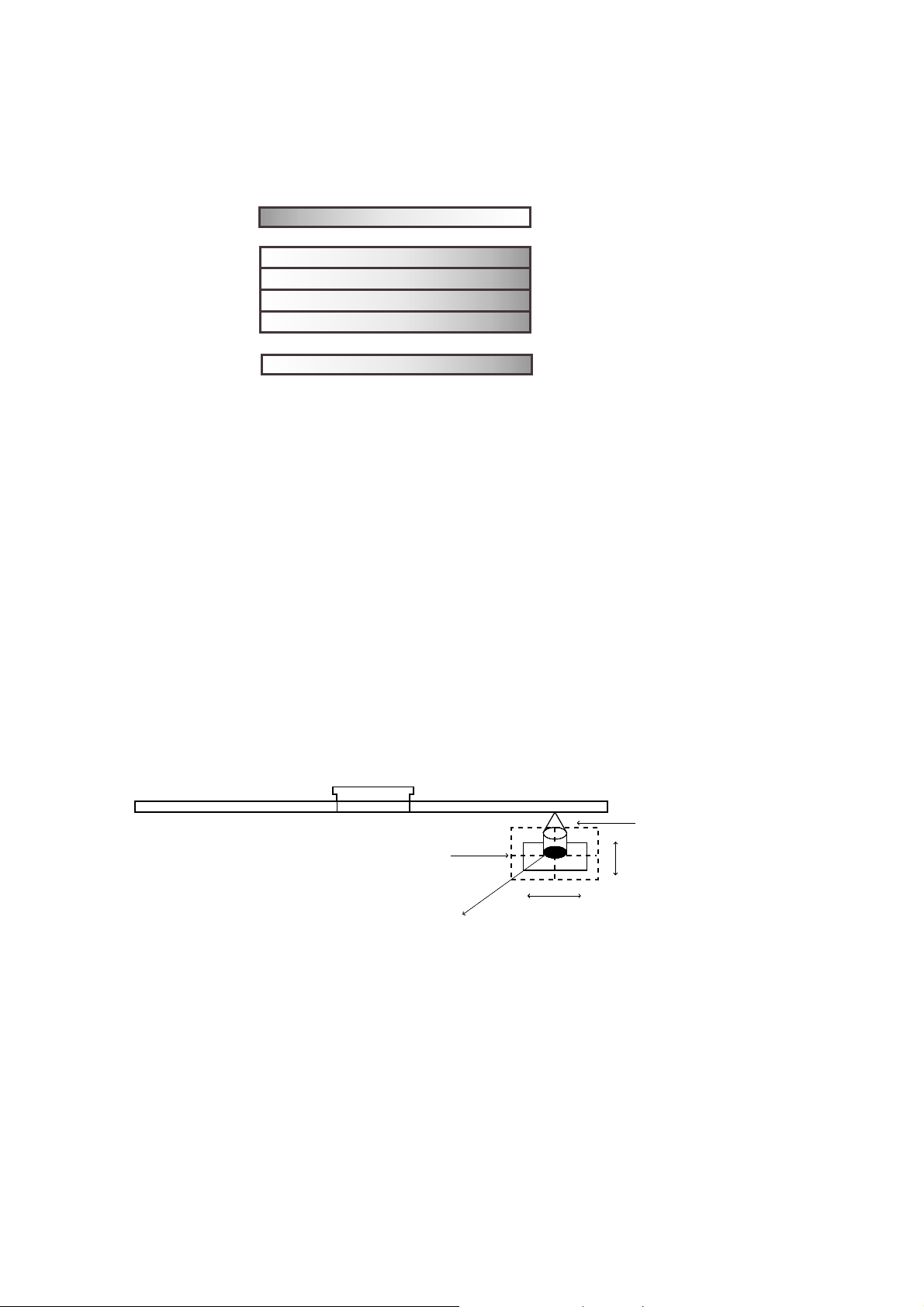
1-3. Cabinet and Main Circuit Board
A. Remove the Cabinet in the direction of arrow (4).
(See Fig. 1-3)
B. Remove the CD Tray drawing forward, by pushing
the Hook(a) backward(5).
C. Remove the Main Circuit Board in the direction of
arrow (6).
D. At this time, be careful not to damage the 4
connectors, are positioned at side, of the Main
Circuit Board.
2. DECK ASSY DISASSEMBLY
2-1. Base Assy
A. Release 1 screw (C) and 2 Stoppers (D).
B. Separate the Base Assy in the direction of arrow (7).
C. Remove the Frame Assy Up/Dowm.
(3)
(2)
Tray Door
Stoppers
CD Tray
Emergency Eject Hole
Front Bezel Assy
Fig. 1-1
DISASSEMBLY
5
(4)
(5)
(6)
Hook (a)
Cabinet
Main
Circuit Board
Fig. 1-3
Fig. 1-2
(8)
(7)
Mechanism Assy
(C)
(D)
(D)
Base Assy
Frame Assy Up/Down
Fig. 1-4
(1)
(A)
Bottom Mecha
(A)
(A)
(A)
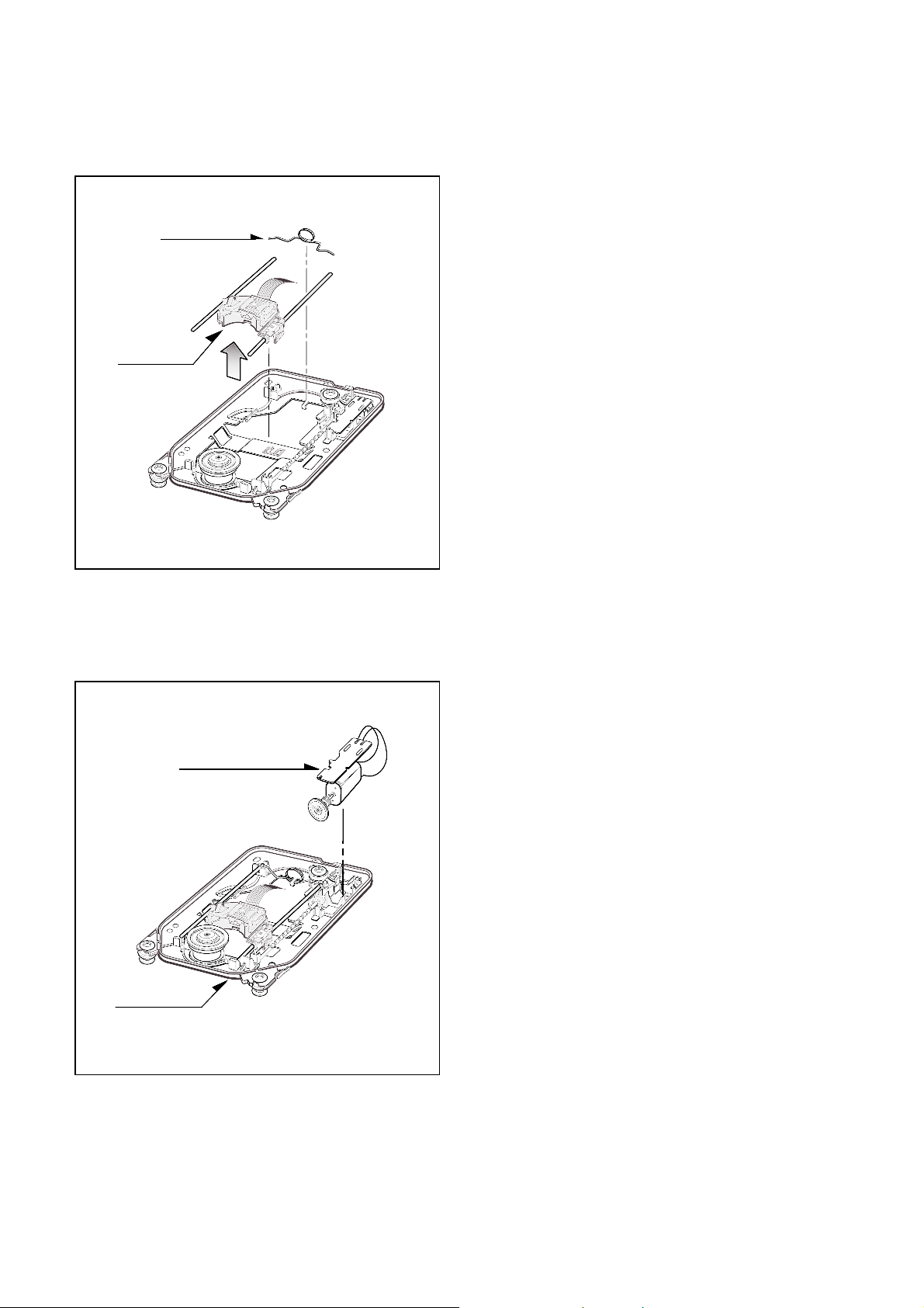
6
2-2. Pick-up Unit
A. Remove the skew spring.
B. Remove the Pick-up Unit.
2-3. Feeding Motor Assy
A. Remove the Feeding Motor Assy by pushing the 2
hooks(b).
B. At this time, be careful the hooks of the Base Pick-up.
Skew Spring
Pick-up Unit
Fig. 1-5
Base Pick-up
Feeding Motor Assy
Fig. 1-6
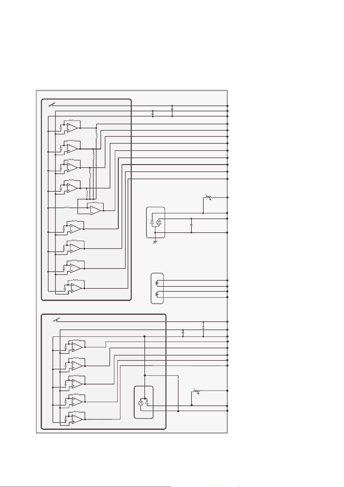
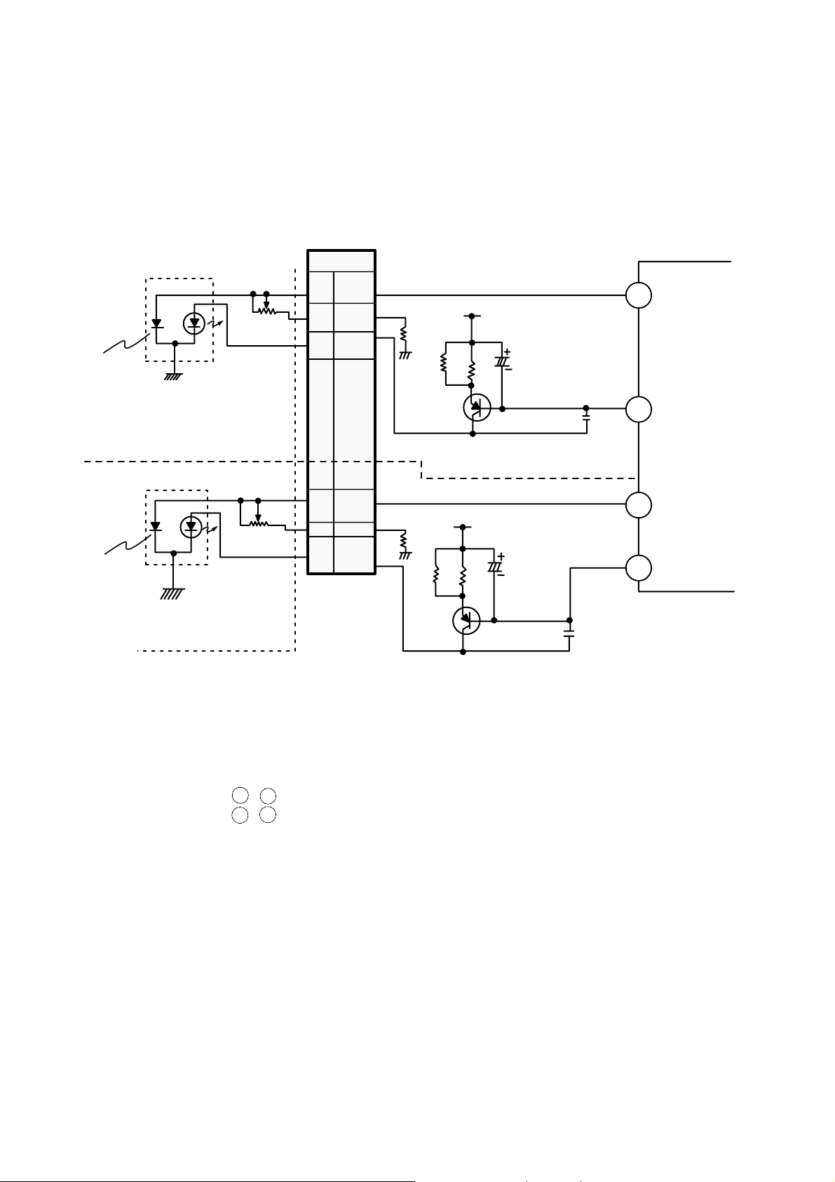
INTERNAL STRUCTURE OF THE PICK-UP
1. Structure of the Pick-Up
10
C001
C002
CN14 DVD PD VCC
CN10 DVD PD VC
CN15 DVD PD GND
CN8 DVD A
CN9 DVD B
CN11 DVD C
CN12 DVD D
CN7 DVD RF
CN13 DVD E
CN5 DVD F
CN19 DVD VR
CN18 DVD MD
CN16 DVD LD
CN15 DVD LD GND
CN1 FO+
CN2 FO-
CN3 TR+
CN4 TR-
CN30 CD VCC
CN20 CD VC
CN26 CD GND
CN25 CD A
CN28 CD B
CN23 CD C
CN24 CD E
CN29 CD F
CN21 CD VR
CN22 CD MD
CN27 CD LD
C010
C011
C012
VR02
U002
U001
TRACKING
FOCUS
C004
ACTUATOR
VR01
LASER DIODE
LASER DIODE
PICK UNIT
11
1) Focus Error Signal –> (A + C) - (B+C)
• In case of CD Disc
This signal is generated in RF AMP IC (IC301 : SSI3723) and controls the pick-up’s up and down to
focus on CD Disc.
2) Tracking Error Signal (3-Beam Method) –> F - E
• In case of CD Disc
This signal is generated in RF AMP IC (IC301 : SSI3723) and controls the pick-up’s left and right shift to
find the track on CD Disc.
3) RF Signal –> A+B+2C
• In case of CD Disc
This signal is converted to DATA signal in DSP IC (IC701 : CXD3030R).
2. Structure of the Photo Diode (CD)
Infrared laser
Pick-Up module
Photo Diode
Tracking
Focusing
(As seen from light
receiving side)
E
C
B
F
A
12
1) Focus Error Signal –> (A+C) - (B+D)
• In case of DVD Disc
This signal is generated in RF AMP IC (IC301 : SSI3723) and controls the pick-up’s up and down to
focus on DVD Disc.
2) Tracking Error Signal (DPD Method) –> Differential phase of (A+C) and (B+D)
• In case of DVD Disc
This signal is generated in RF AMP IC (IC301 : SSI3723) and controls the pick-up’s left and right shift to
find the track on DVD Disc.
3) RF Signal –> A+B+C+D
• In case of DVD Disc
This signal is converted to DATA signal in DSP IC (IC201 : CXD1867R).
3. Structure of the Photo Diode (DVD)
(As seen from light
receiving side)
Red laser
Pick-Up module
Photo Diode
Tracking
Focusing
F
D
C
B
A
E
13
PN301
18
19
16
R317
R318
C332
C335
Q302
C331
C333
CD LD
CD PD
DVD LD
IC301 SSI3723
DVD PD
Q303
R315
R316
Vcc
5V
Vcc
5V
22
27
DVD MD
DVD-
VR
DVD LD
LD
LD
CD PD
CD-VR
CD LD
DVD-LD(LASER DIODE)
CD-LD(LASER DIODE)
PICK-UP Unit
Monitor
Diode
Monitor
Diode
22
24
21
23
21
1-2. APC Circuit Operation
It drives the LD to the constant current and adjusts the LD input current , so that the output current is
constant.
IC301 (SSI3723) Pin , : PD IN, Monitor Input of Laser diode APC
IC301 (SSI3723) Pin , : LD OUT, External Current Driver Control output of the LD (Laser Diode)
The detect current from the monitor diode converts to the I/V (Current/Voltage) at the external resistor.
Beforehand, it adjusts a fixed level over for a standard GND.
If this voltage inputs to the PD IN (IC301 Pin 23, 24), it is amplified about 36.4 times (about 31.2dB).
So this voltage outputs from the LD OUT (IC301 Pin 21, 22).
The LD driving element (Q302/Q303) uses the TR more than 200hfe, and controls LD OUT (IC301 Pin 21,
22) connected to the base of Q302/Q303.
The APC control for the each DVD/CD sets Register of the IC301 (SSI3723) according to Disc in the
µ-COM.
DESCRIPTION OF CIRCUIT
1. APC (Automatic Power Control) Circuit
1-1. APC Circuit Constitution
23
24
21
22
14
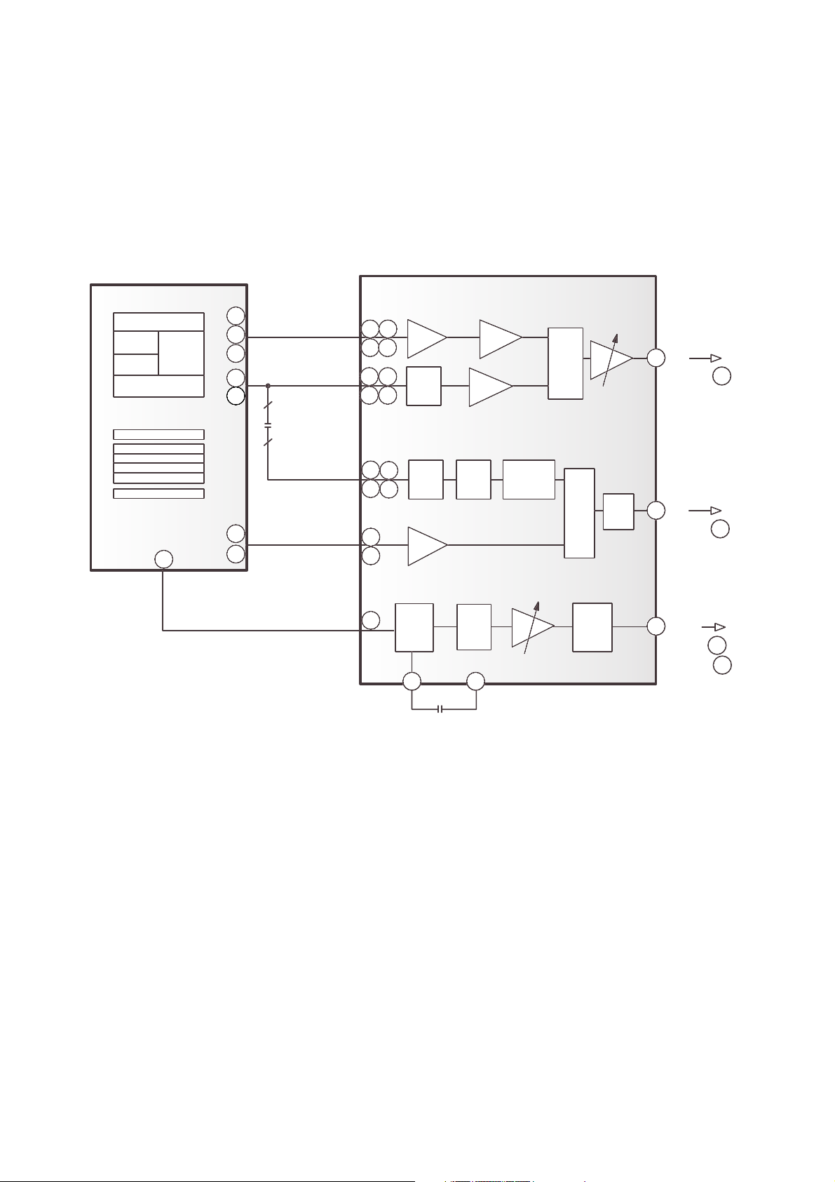
E
A
B
C
F
F
D
C
B
A
E
23
25
28
8
9
24
3
4
29
1
7
CD (A, B, C)
DVD RF
17
18
64
5
6
9
10
11 12
13
14
15
16
AMP
AMP
MUX
ATT
AGC
AGC
40
GCA
GCA
SUM
AMP
BUFF
MUX
MUX
FE
TE
RF AC
To IC701 38
To IC701 36
To IC701 47
To IC202 117
GCA
39
57
EQ
Phase
Detector
EQ
DVD (A, B, C, D)
DVD
(A
2
, B2, C2, D2)
CD (E, F)
Pick-up Unit
PN301
IC301
SSI3723
4
4
RF DC
RF SIN
63
2. RF Amplifier Circuit
2-1. RF AMP Constitution
15
FOCUS & TRACKING SERVO PROCESS
SLED(Feed) SERVO PROCESS
F
F
D
C
B
A
B
A
E
E
C
Pick - Up
IC301
RF AMP
SSI3723
5
CD
E-F
(A. B. C. E. F)
6
DVD (A. B. C. D.)
TE/
DPD TE
SELECTOR
FE
Generating
DPD TE
Generating
TE
FOCUS
ERROR
DETECTOR
FOCUS &
TRACKING
ACTUATOR
IC501
DRIVE
BA5983FM
IC701
CD/DVD SERVO & DSP
CXD3030R
F+ F-T+ T-
LEVEL SHIFT
LEVEL SHIFT
FAO
TAO
D/A
DIGITAL
EQUALIZER
(AUTO ADJUSTMENT
CIRCUIT)
SLED
Control
Signal
A/D
TE FE
TE
SAO
SLED MOTOR
Hall Sensor
M
PHO - C
PHO - A
FEED. MOTOR+
FEED. MOTOR-
LEVEL SHIFT
IC501
Q501
DRIVE
BA5983FM
KTD1304
+
IC201
u-COM
SLGNCHG
SLED CLK
(A. B. C)
(A. B. C.D)
(A
2
. B2. C2 .D2)
3. Focus/Tracking/Sled Servo Circuit
3-1. FOCUS, TRACKING & SLED SERVO PROCESS

16
3-2. Focus Servo for CD/DVD
Focus Servo for CD/DVD is based on focus error signal generated from RF AMP (SSI3723). It standardizes the
laser beam (CD : A, B,C, DVD : A, B,C,D) radiated from the pick-up.
Each other focus gain or path is made at the SSI3723 (IC301) according to the disc, Focus Error signal
output from the FE terminal and input to Servo IC (IC701 CXD3030R).
After the first amplification of this signal, the signal is converted to A/D and input to Digital Equalizer Block
assigned the most important part at the Focus Servo, and generates the focus servo with coefficient value
set at the µ-COM through the Digital Filter.
At this Digital Equalizer, auto adjustment for Focus Balance or Focus Loop Gain occurs and the basic offset
value for pick-up is accepted on the balance mode, and set the focus standard level to this value.
After the signal for Focus Servo is converted to the D/A and output through FAO (IC701 CXD3030R ).
This signal drives Focus Actuator through the Focus Drive IC (IC501:BA5983FM).
3-3. Tracking Servo for CD/DVD
For Tracking Servo, CD uses 3 Beam method (E-F), DVD uses DPD (Differential Phase Detect) method
[Phase (A+C) - Phase (B+D)]
According to the disc, Tracking Error is set at SSI3723, Gain or Path differs from each other, and the
generated signal output through the TE terminal.
This signal input to TE of IC701, after the first amplification, and converted to A/D.
The signal converted to A/D input to the Digital Equalizer assigned the most important part at the Tracking
Servo, Tracking Servo Gain is generated with Digital Filter coefficient value set according to the disc at the
µ-COM.
* Tracking signal is converted to D/A through the pin TAO terminal of IC701 and input to IC501
(BA5983) tracking drive.
This drive drives the tracking actuator actually.
3-4. Sled Servo (Feed Servo) for CD/DVD
Sled servo operates related with a tracking servo basically
It goes with the progressive track speed according to the disc rotation speed.
Sled drive voltage is generated with a accumulated capacity of tracking error signal and is applied sled
movement voltage according to the track movement capacity, and this voltage outputs to the pin FAO of
IC701. This value is the sled motor drove by the IC501 (Sled drive : BA5983FM). But, the shift speed
for pick-up is not controlled and broke with a only sled servo, itself, in the data access mode, and the
feedback is used according to the sled shift speed at this time. So, the accurated shift speed for
pick-up is controlled added to the sled signal.
The hall sensor is used in the feedback and SLEDCLK (95) output at the µ-COM (IC203) is used with it
in the sled kick or break.
4
3
113
17
E
A
B
C
3
4
F
M
PICK-UP
SPINDLE MOTOR
A+B+2C
CD RF
DVD RF
A+B+C+D
IC203
IC701
PLL BLOCK
FG
PLL BLOCK
DVD RF
CD RF
Motor
Hall Sensor
U
HU+
HUHV+
HVHW+
HW-
6
V
W
Speed
Monitoring
u-com
CD/DVD SERVO & DSP
CXD3030R
IC301
RF AMP
SSI3723
IC201
DVD DSP
CXD 1867R
IC401
DRIVE
BA6664FM
SPINDLE SERVO PROCESS
LEVEL SHIFT
A, B, 2C
A, B, C, D
RF
RF
A
D
C
B
MDP CD
SPDG0
SPDG1
2
4. Spindle Servo Circuit
4-1. SPINDLE SERVO PROCESS
4-2. Spindle Servo for CD/DVD
DRD-8080B consists of the three spindle control respectively.
(1) DVD x 8 : CAV (DVD Single, Dual Layer)
(2) CD x 16 (max.) : CAV (CD-DA, CD-RW(8-20 x), Video-CD(8x CLV), Host command stand-by of CDROM and CD-R)
(3) CD x 40 (max.) : CAV (CD-R, CD-ROM play mode)
In the spindle speed control mode respectively.
CD x 16(Max)/CD x 40(Max) CAV drives CAV servo with PLL of RF data read and received MDP.
(Pin 12 of IC701)
DVD x 8 (Max) CAV drives CAV servo with FG signal and received MDP CD. (Pin 12 of IC701)
18
DESCRIPTION OF DATA PROCESSING
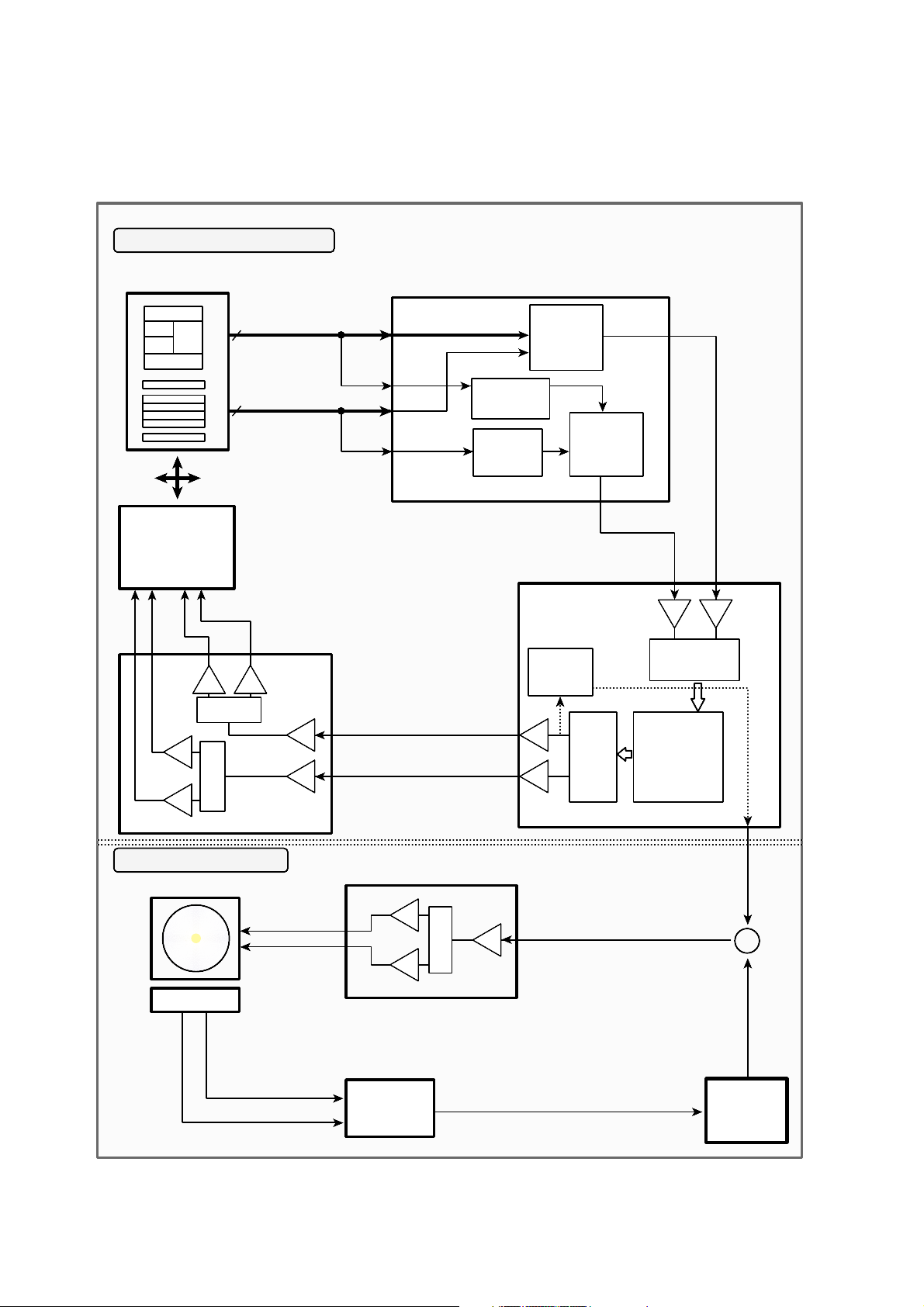
1. CD Data Processing Flow
CD
Pickup
Unit
Motor
Drive
Generating
A/B/2C/E/F Signal
H8/3062
Buffer
CD Data Buffering
CXD1867R
CD-ROM Decoder
and Host Interface
CXD 3030R
CD DSP
SSI3723 RF
Signal processing IC
CD TE/FE/SLED
Spindle Control
Command
Data
Status
SDATA
CD DATA
CD RF
MA [0..8]
MDB [0..F]
DATA [0..7]
ADR [0..8]
SICLK
SIXLT
SIDAT
SCLK
CD Data ECC
Receive the order from Host
2'nd ECC
CD Data Buffering
Generating RF Signal
Generating Tracking Error
Generating Focusing Error
CD Servo Control
CD Data Flow Control
Host Command Receive or Data/Status Transfer
Error Correction
Generating Header Sync
Generating Subcode Sync
EFM Demodulation
19
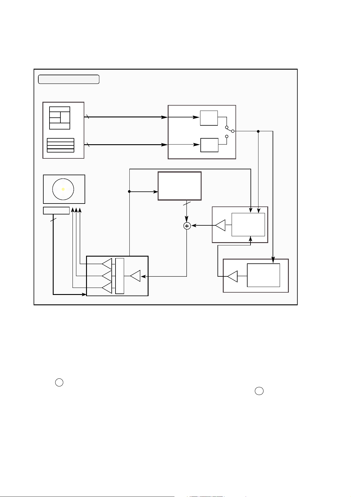
2. DVD Data Processing Flow
DVD
Pickup
Unit
Motor
Drive
DVD
TE/FE/Sled/
Spindle control
Sled Control
CXD 3030R
CD DSP
H8/3062
Buffer
CXD1867R
DVD DSP
Command
Data/
Status
DVD RF
DATA [0..7]
ADR [0..8]
MA [0..8]
MDB [0..F]
Generating
A/B/E/F Signal
SSI3723 RF
Signal processing IC
Generating RF Signal
Generating Tracking Error
Generating Focusing Error
Error Signal
Receive the Command from Host
DVD Data Buffering
Copy Protection Control
DVD Data Buffering
DVD Servo Control
DVD Data Flow Control
Host Command Receive or Data/Status transfer
EDC + ECC processing
Generating DVD ID Sync
EFM Demodulation

20
CXD 1867R
HOST DVD
PLAYER
(MPEG2 B/D)
H8/3062
Scrambled MPEG Data
Change the "KEY"
KEY Management Control
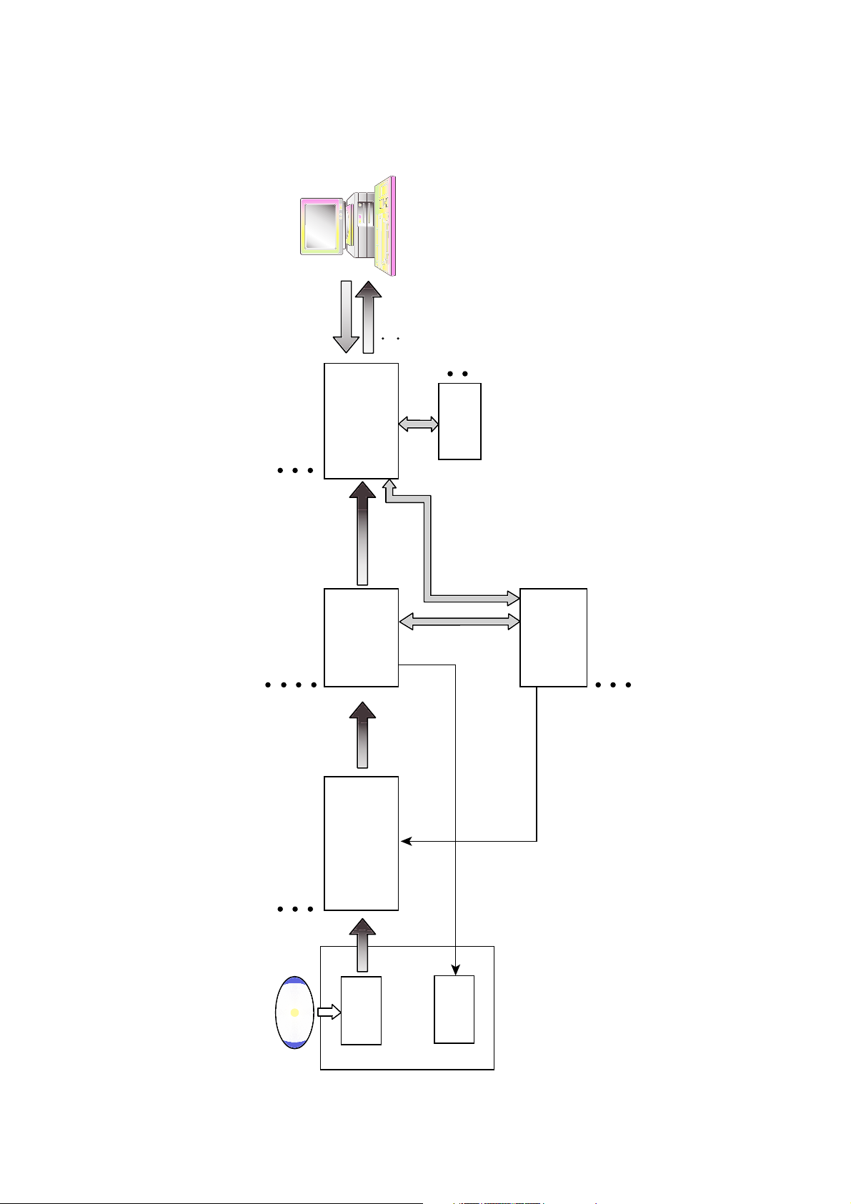
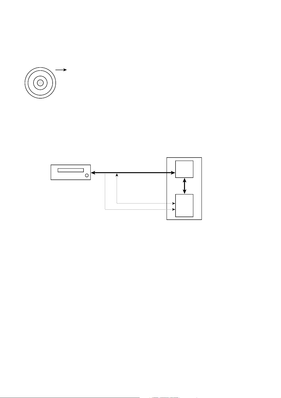
3. Copy Protection and Regional Code Management Block
Block Diagram
Brief Process
1. Regional Code for DVD Disc
– DVD-ROM drive transfers the regional code of the control data to host by the command of host, the DVD
player of host reads the regional code, and plays title in the case of allowed regional code only.
2. Management of DVD Disc for the scrambled of data
(1) DVD-ROM and DVD player of host generate the “KEY 1” respectively, transfer to opposite part, the
“KEY 2” is received, recognizes the data transfer or not with this value, and generates the bus key
encoded the data.
(2) Encoded “Disc Key” and “Title Key” host is transfer with the bus Key.
(3) DVD player of host reads the key value, and uses the value to restore the scrambled data.
* Refer to the next page for the details.
21
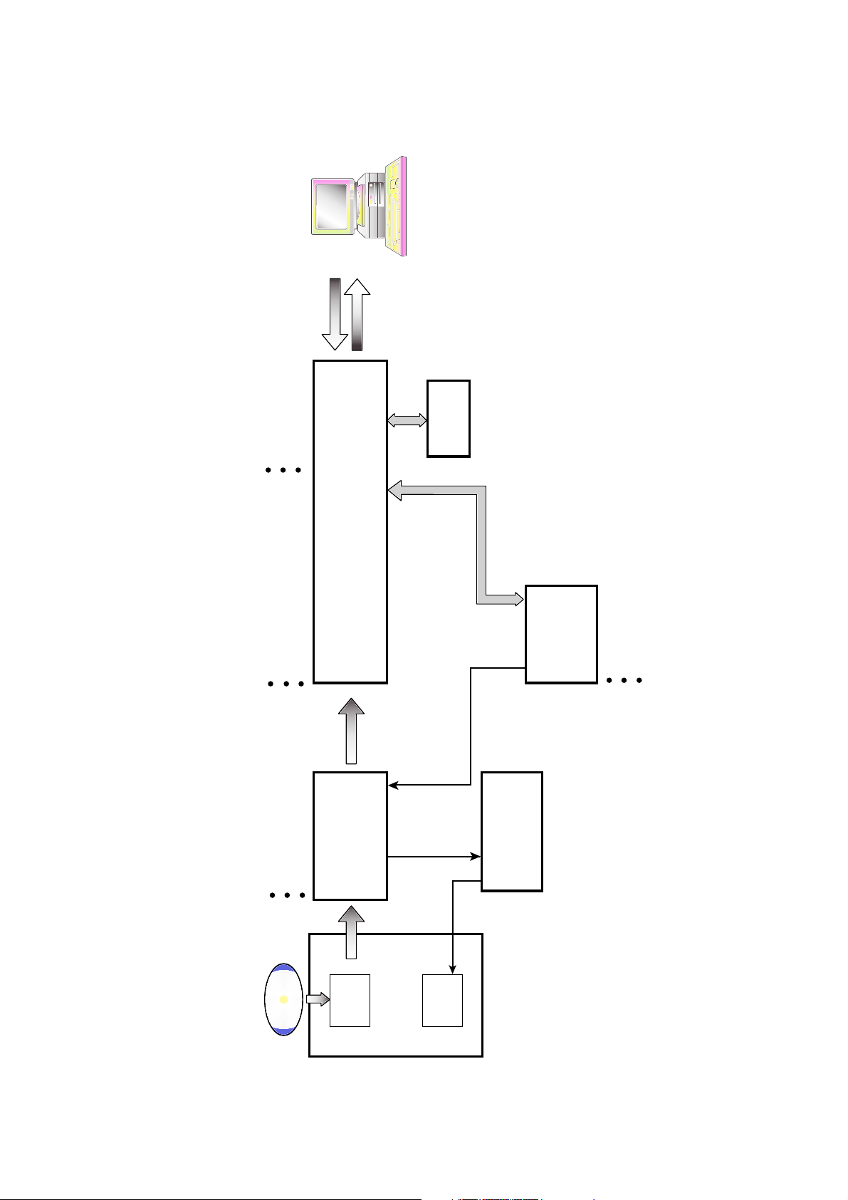
4. About Prevention the DVD-ROM from to be copy
A data is able to encode and record in the disc, if a copyright holder wants to prevent the disc from copying.
In case of a disc enhanced movie of 3 titles......
DISC KEY (2048 Bytes) is used to encode the whole contents in the disc and TITLE
KEY (5 Bytes) is used to encode the title respectively.
So, the data is encoded and stored in a disc through the unknown algorithms
with a disc key and title key. (At this time, the disc key and title key are stored
in a disc.)
…As above, the disc is able to copy when the disc key and title key are
opened.
Then, ROM-DRIVE encodes the disc key and title key and transfers to MPEG2 board.
If you want to play the disc prevented from the copy......
First of all, ROM-DRIVE and MPEG-2 board identify with each other through the procedure as described
below.
1. Drive and host gives and takes the ID of 2bit. This ID is AGID (Authentication Grant ID).
The various decoder boards are attached to the host, in these, AGID sets the MPEG-2 board and drive.
2. After the AGID is set, MPEG-2 board generates the challenge key (10 Byte) and transfers to drive. The
board and drive generate key 1 (5Byte) with the challenge key respectively. (Of course, the Algorithm
generating the key 1 is not known.)
3. Compare with the generated key 1, if it corresponds each other, the first step of authentication is
completed. This is a course to identify the MPEG-2 board with a drive.
4. The second step of authentication is a course to identify a drive with the MPEG-2 board.
The dirve generates a challenge key and transfers it to the MPEG-2 board. The dirve and MPEG-2 board
generate the key 2 (5Byte) with the challenge key, compare with each other, and if it corresponds and the
secondary step of authentication is completed.
5. As above, the identification is completed.
6. The dirve and MPEG-2 board generate the Bus key with the key 1 and key 2 and own it.
7. Dirve encodes the disc key and title key with this Bus key and transfers to the MPEG-2 board.
8. The MPEG-2 board reads the encoded disc key and title key with the Bus key only.
9. MPEG-2 board lets data read from the drive to decode with the read disc key and title key and makes into
the video signal by decoding.
ROM-DRIVE
AGID
HOST
MPEG-2
BOARD
Challenge key
encoded disc key, title key
 Loading...