

LG TRAINING MANUAL
LG TRAINING MANUAL
Steam Dryers DLEX8377*M/DLG8388*M
Fall 2008
Published August 2008 by LG Electronics USA Trainng Center
Copyright © 2008 LG Electronics of Alabama, Inc.
Ph o n e Co n t a C t s :
Contact Number Hours of Operation
Customer Service (800) 243-0000 24/7 - 365 days a year
Technical Support (800) 847-7597 7am-7pm Mon-Fri / Sat 8-2 CST
Parts Sales (888) 393-6484 7am-7pm Mon-Sat CST
Training Center (256) 774-4051 8am-5pm Mon-Fri CST
e b Co n t a C t s :
W
Web Site Address Description
LG USA www.lgusa.com USA sales site
Customer Service us.lgservice.com Customer support
GCSC aic.lgservice.com Service center support
Customer Service Academy www.LGCSAcademy.com Technical training

TRAINING MANUAL
DLEX8377WM
IMPORTANT SAFETY NOTICE
The information in this training manual is intended for use by persons possessing an adequate background
in electrical equipment, electronic devices, and mechanical systems. In any attempt to repair a major
appliance, personal injury and property damage can result. The manufacturer or seller maintains no liability
for the interpretation of this information, nor can it assume any liability in conjunction with its use. When
servicing this product, under no circumstances should the original design be modified or altered without
permission from LG Electronics. Unauthorized modifications will not only void the warranty, but may lead
to property damage or user injury. If wires, screws, clips, straps, nuts, or washers used to complete a
ground path are removed for service, they must be returned to their original positions and properly
fastened.
CAUTION
To avoid personal injury, disconnect the power before servicing this product. If electrical power is required
for diagnosis or test purposes, disconnect the power immediately after performing the necessary checks.
Also be aware that many household appliances present a weight hazard. At least two people should be
involved in the installation or servicing of such devices. Failure to consider the weight of an appliance could
result in physical injury.
ESD NOTICE
Some of the electronic components in appliances are electrostatic discharge (ESD) sensitive. ESD can
weaken or damage the electronics in these appliances in a manner that renders them inoperative or
reduces the time until their next failure. Connect an ESD wrist strap to a ground connection point or
unpainted metal in the appliance. Alternatively, you can touch your finger repeatedly to a ground
connection point or unpainted metal in the appliance. Before removing a replacement part from its package,
touch the anti-static bag to a ground connection point or unpainted metal in the appliance. Handle the
electronic control assembly by its edges only. When repackaging a failed electronic control assembly in an
anti-static bag, observe these same precautions.
REGULATORY INFORMATION
This equipment has been tested and found to comply with the limits for a Class B digital device, pursuant
to Part 15 of the FCC Rules. These limits are designed to provide reasonable protection against harmful
interference when the equipment is operated in a residential installation. This equipment generates, uses,
and can radiate radio frequency energy, and, if not installed and used in accordance with the instruction
manual, may cause harmful interference to radio communications. However, there is no guarantee that
interference will not occur in a particular installation. If this equipment does cause harmful interference to
radio or television reception, which can be determined by turning the equipment off and on, the user is
encouraged to try to correct the interference by one or more of the following measures: Reorient or
relocate the receiving antenna; Increase the separation between the equipment and the receiver; Connect
the equipment to an outlet on a different circuit than that to which the receiver is connected; or consult
the dealer or an experienced radio/TV technician for help.
DISCLAIMER
The information in this training manual was accurate at the time of publication. Every effort has been made
to ensure accuracy. Updates, changes, etc. are available via GCSC and LGCSacademy. The information in
this manual is intended for persons with adequate backgrounds in electronics, mechanical, and electronic
servicing. The manufacturer and seller are not to be held responsible for any liability incurred from its use.
COMPLIANCE
The responsible party for this device’s compliance is LG Electronics Alabama, Inc.; 201 James Record Road,
Huntsville, AL, 35813.
DLEX8388WM
Page 1
STEAM DRYER

TRAINING MANUAL
DLEX8377WM
Contents
Important Notices (The Small Print Page) 1
Contents 2
Introduction 3
LCD Control Panel 4
LED Control Panel 5
Safety Notices 6
Warranty Information 7
Specifications 8
Accessories 9
Drying Rack Installation 9
Stacking Kit Installation 10
Makeup Air 11
Pedestal 12
Remote Laundry Monitor Installation 14
Electrical Connection (Electric Dryer Only) 15
Gas Connection (Gas Dryer Only) 18
Dryer Cycle Chart 19
Steam Cycle Information 20
STEAMFRESH™ 20
Reduce Static 20
Easy Iron 20
Display PWB 21
Main Control Board 21
Main Control Board (Photo, with connectors labeled) 22
Schematic (Electric Dryer) 23
Schematic (Gas Dryer) 24
Diagnostic Test Mode 25
Component Testing Procedures 26
Motor Diagram and Schematic 29
Safety Switches 30
Centrifugal Switch 30
Belt Switch 30
Diagnostic Test Procedures 31
Test 1 – AC Electrical Supply 31
Test 2 – Thermistor Test (Power Off) 34
Test 3 – Motor Test 35
Test 4 – Moisture Sensor Test 36
Test 5 – Door Switch Test 37
Test 6 – Heater Switch Test (Electric Dryer Only) 38
Test 7 – Gas Valve Test (Gas Dryer Only) 39
Test 8 – Semiconductor (Sensor) Test 40
continued on next page Æ
DLEX8388WM
Page 2
STEAM DRYER

TRAINING MANUAL
DLEX8377WM
Contents, continued
Gas Conversion (Natural Gas to Propane) 41
Regulator Conversion 42
Orifice Change 42
Gas Pressure Testing 43
Gas Valve Operation 44
Disassembly and Repair Instructions 45
Top Plate (Cover) 45
Panel Drawer (Water Container) 45
Control Panel 46
Front Cabinet 47
Door Reversal 47
Guide Assembly (for Steam Generation) 48
Steam Generator 49
Steam Generator Troubleshooting 50
Main Components 50
Theory of Operation 50
Thermistor Testing 51
Pump Motor Testing 51
Panel Body and Frame 53
Tub Front (Front Bulkhead) 53
Drum, Belt, and Pulley 54
Drum Lamp 55
Vent Replacement (Side Venting Kit) 56
Additional Venting Information 57
Static Pressure Testing and Vent Kit 58
Filter Assembly and Moisture Sensor 59
Rear Bulkhead 59
Air Duct 59
Rollers 60
Blower Housing 61
Exploded Views 62
Parts List 67
Supplementary Materials 70
Serial Number Identification 70
Ohm’s and Watt’s Laws (Chart and Formulae) 71
Temperature Conversion (Chart and Formulae) 72
Service Bulletins 73
DLEX8388WM
Page 3
STEAM DRYER
TRAINING MANUAL
DLEX8377WM
INTRODUCTION
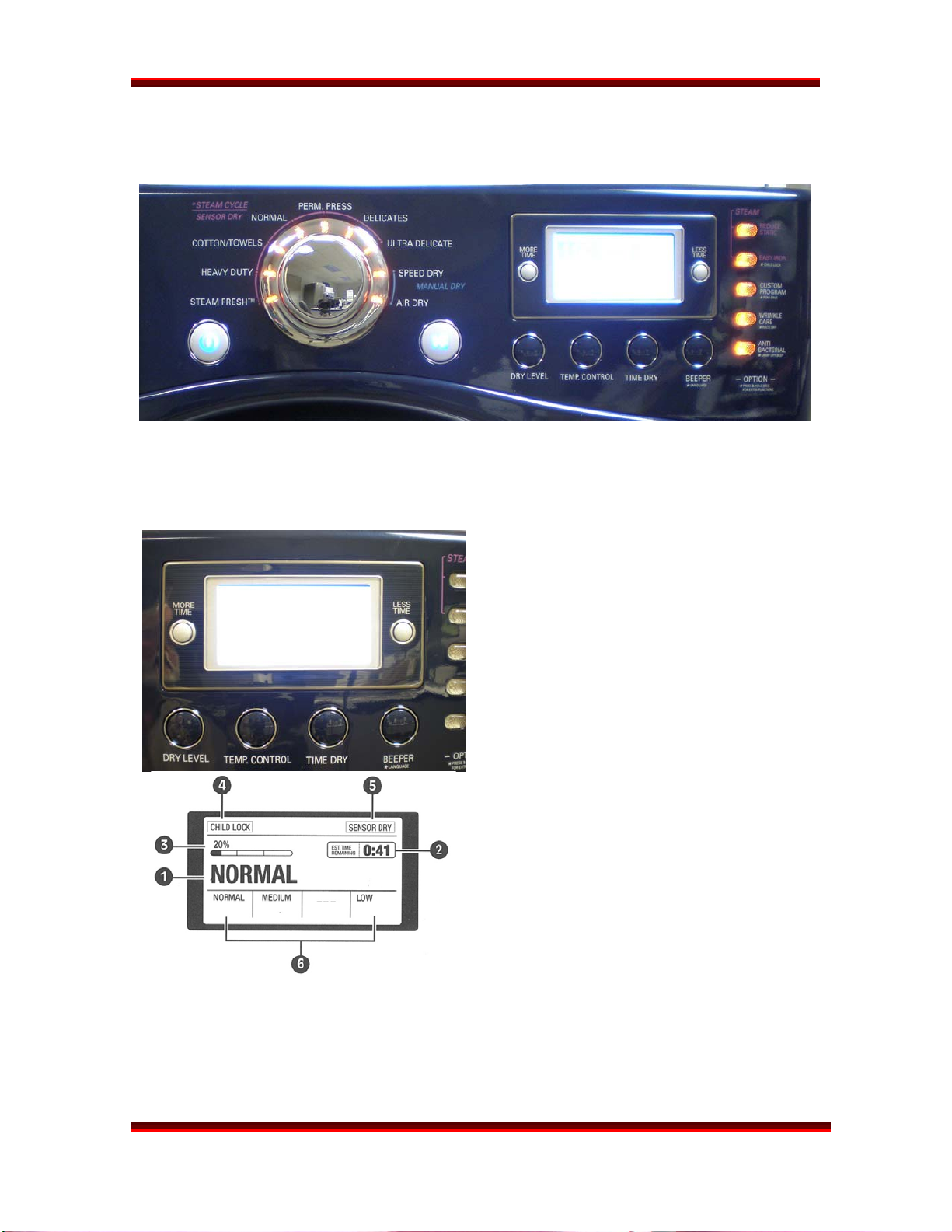
MAIN CONTROL PANEL
The Steam Dryer is available in two models. The top end model includes an LDC control
panel while the next model down has LEDs instead. Both models function similarly. (See
photo, next page.)
The LCD control panel includes a display
window and an array of option buttons.
The steam feature buttons (REDUCE
STATIC and EASY IRON) add these steam
features to the end of any of the sensor
cycles available.
(See complete explanation on page 20.)
DLEX8388WM
1. Cycle selected
2. Approximate time remaining on cycle
3. Progress indicator (%age complete)
4. Child Lock indicator
5. Sensor cycle indicator
6. Indicators – refer to the option buttons
below the window. These buttons allow
the user to override the default settings
on many cycles.
Error messages are displayed in the LCD
window as well.
Page 4
STEAM DRYER
TRAINING MANUAL
INTRODUCTION, continued
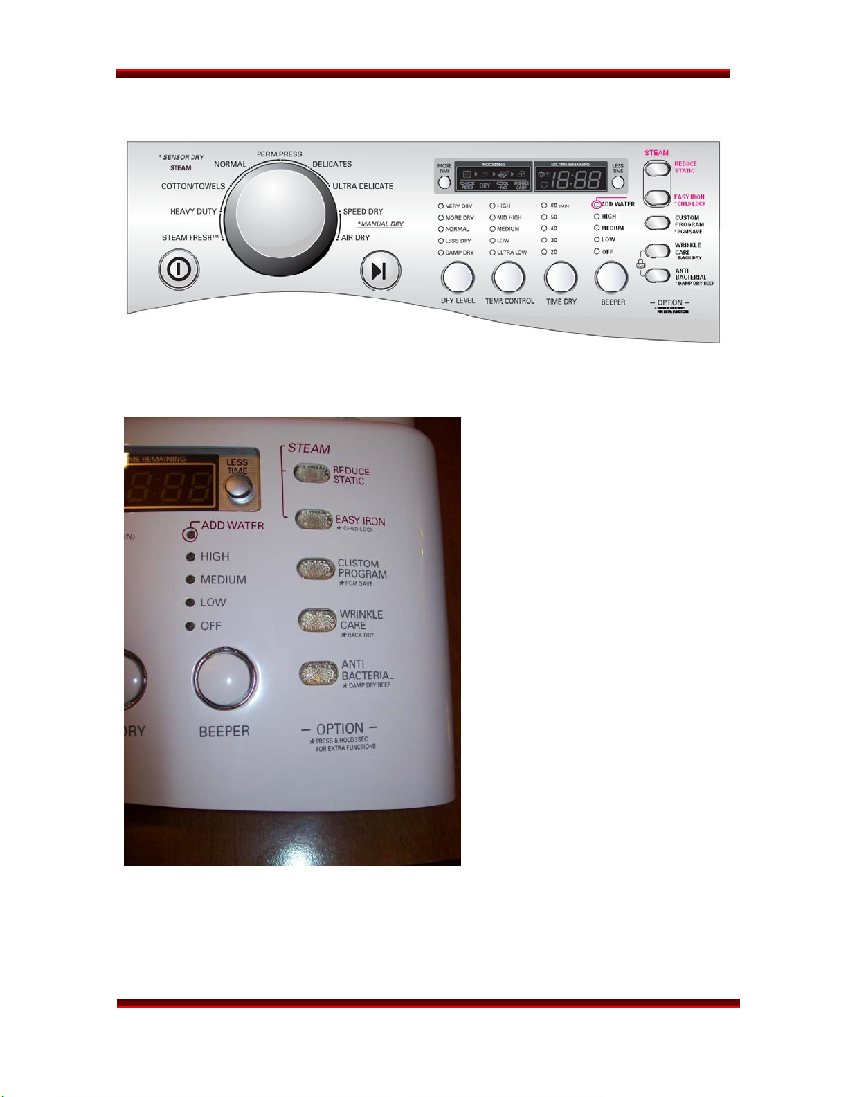
MAIN PANEL
DLEX8377WM
New features on the control panel
include the STEAM FUNCTION
BUTTONS and the ADD WATER
warning lamp.
The option buttons are the same on
both types of control panel.
DLEX8388WM
Page 5
STEAM DRYER
TRAINING MANUAL
SAFETY
DLEX8377WM
Check the local laws and regulations concerning the installation and connection of gas. In
most localities, it is illegal to connect gas piping, re-jet or adjust burners, or repair gasfired equipment unless you are licensed and certified so to do. It is the servicer’s
responsibility to comply with all such regulation.
The STEAM GENERATOR operates at a high temperature (hot enough to boil water.)
When servicing the steam generator, let it cool before beginning work. Hot water and
steam can cause severe burns and injuries.
DLEX8388WM
Page 6
STEAM DRYER
TRAINING MANUAL
DLEX8377WM
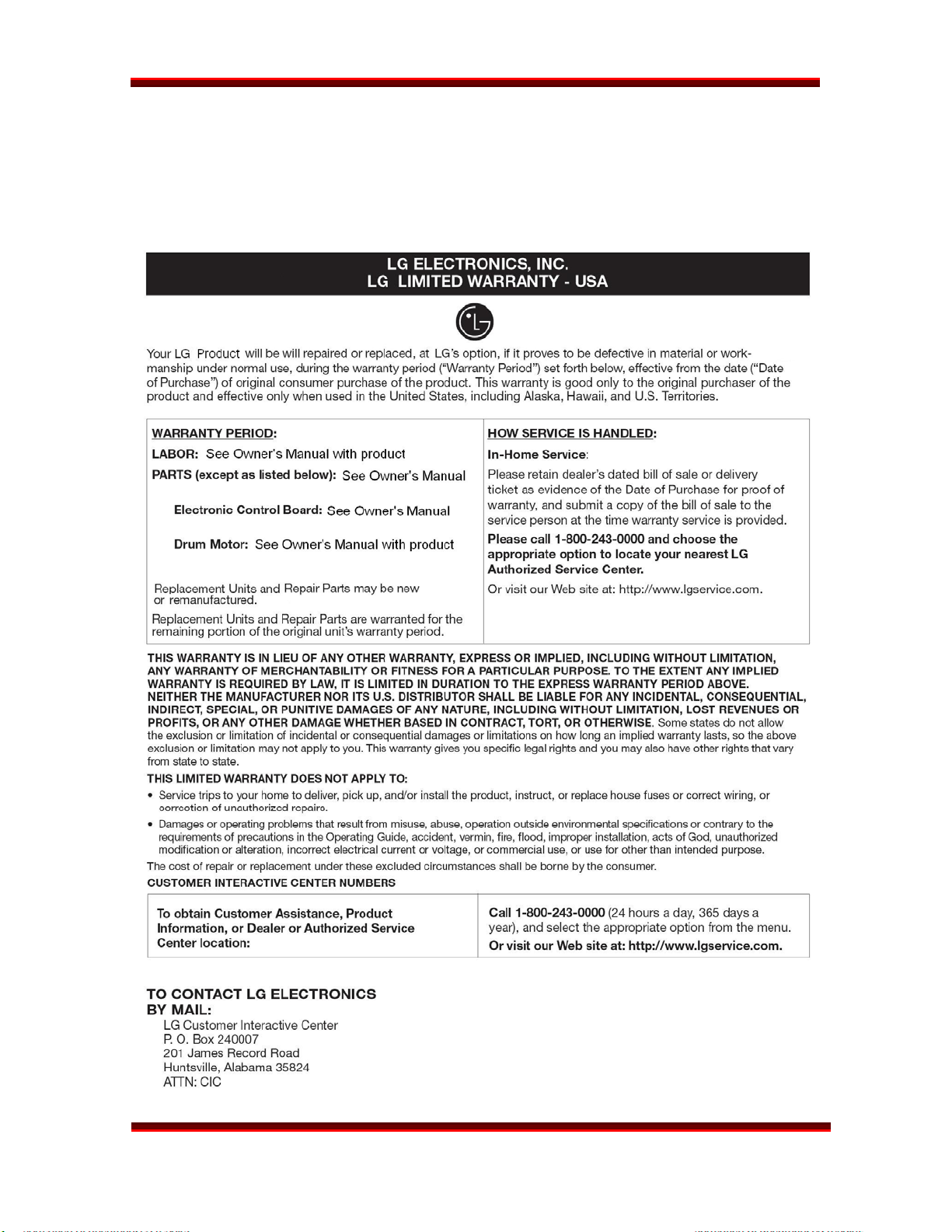
WARRANTY
Warranty statements vary by product. Be sure to check the warranty that was included
with the product because that is the valid warranty. This statement is generic and for
instructional purposes only.
DLEX8388WM
Page 7
STEAM DRYER
TRAINING MANUAL
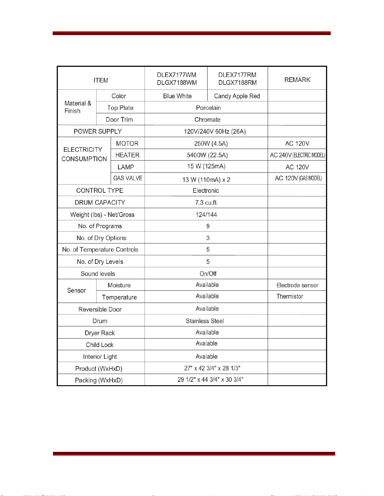
SPECIFICATIONS
DLEX8377WM
Specifications are subject to change without notice.
DLEX8388WM
Page 8
STEAM DRYER
TRAINING MANUAL
DLEX8377WM
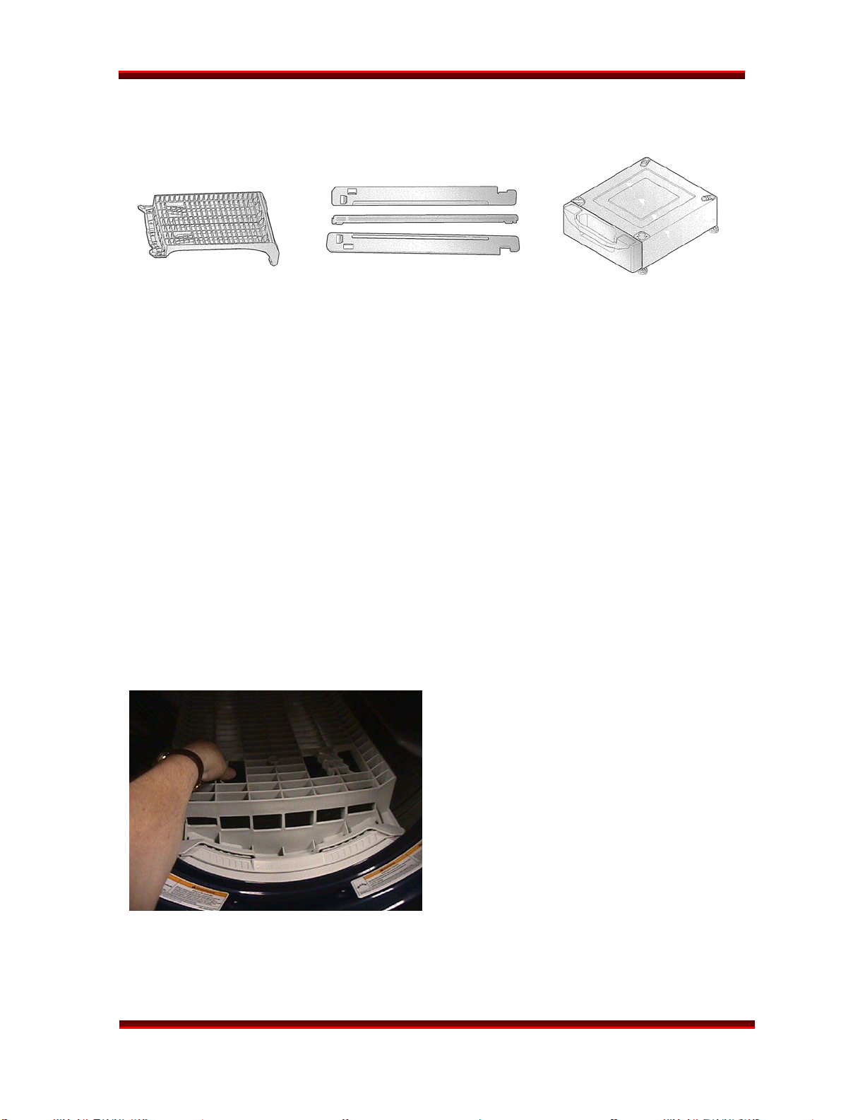
ACCESSORIES
DRYING RACK STACKING KIT PEDESTAL
The DRYING RACK is used to dry items that should not be tumbled, like sweaters, tennis
shoes, etc. It should be removed and stored when not in use. The rack is included with
the dryer. (See installation procedure, below.)
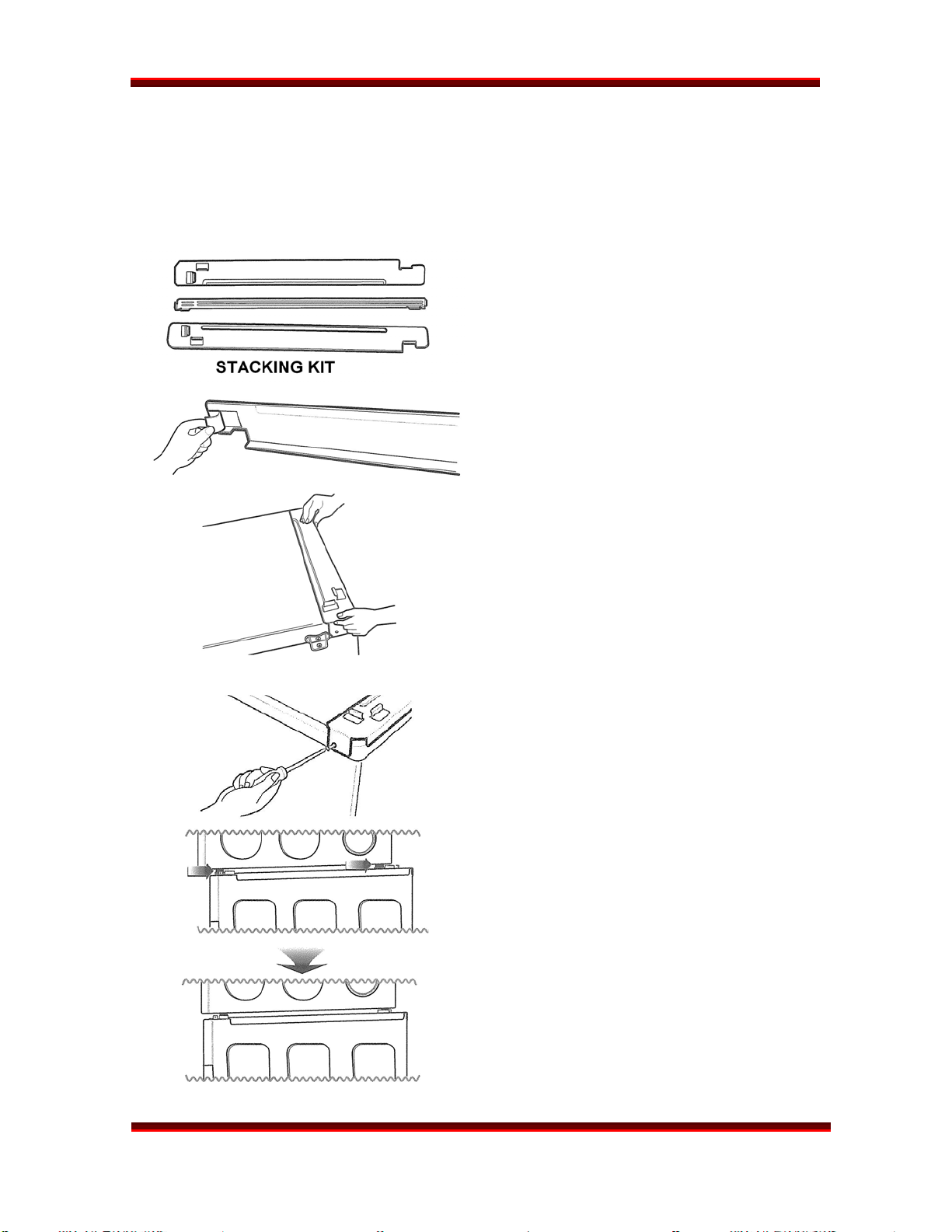
The STACKING KIT is used to stack a dryer on top of a matching washer. (NEVER put a
washer on top of a dryer!) The stacking kit should not be used in situation where there is
the possibility of excessive vibration and movement of the washer, such as in a mobile
home or an upper floor of a frame structure. The stacking kit is available as an optional
purchase. (See installation procedure, page 10.)
The PEDESTAL can be used under either the washer or the dryer. It is possible to stack a
washer and dryer on a pedestal, but the dryer controls may be difficult to reach and the
possibility of vibration and movement is greater. The pedestal is available as an optional
purchase. (See installation procedure, pages 12 ~ 13.) Pedestals are available in heights
of 7¼” and 13”.
DLEX8388WM
INSTALLATION (RACK)
Open the dryer door.
Put the rack in place.
Select RACK DRY (2nd button on right)
Press START.
Be sure the front of the rack is properly
situated in the notches on either side
of the filter. The back should rest on the
drum and allow the drum to rotate.
Page 9
STEAM DRYER
TRAINING MANUAL
DLEX8377WM
INSTALLATION (Stacking Kit)
WARNING! Do not attempt this alone! At least two people are required to lift the dryer
and place it properly on top of the washer. Failure to observe this warning could result in
serious physical injury and damage to the appliances.
Place the washer on a solid, even floor. If
you plan to use a pedestal, install it now
before going any further.
Peel the protective paper from the
adhesive tape on the side bracket.
Fit the side bracket firmly to the top plate
using the adhesive tape, as shown in the
drawing.
Secure the bracket to the top plate using a
screw, as shown.
Repeat these steps for the other side.
Level the dryer on a firm solid floor and
lock down the adjusters before placing it
on top of the washer.
Lift the dryer on top of the washer it
toward the front of the washer, as shown.
Slide the dryer all the way back to the stop
on the rail.
DLEX8388WM
Page 10
STEAM DRYER
TRAINING MANUAL
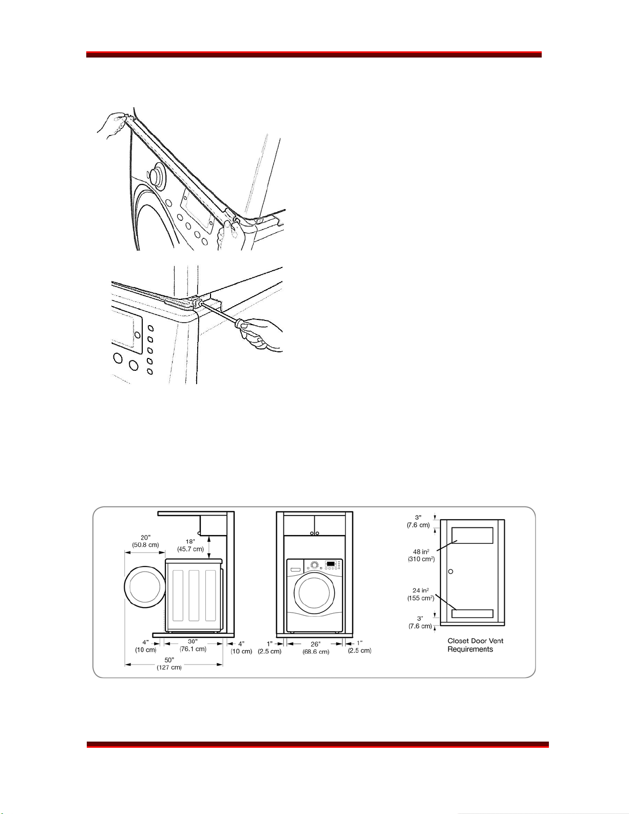
INSTALLATION (Stacking Kit) continued
Install the front rail of the stacking kit. Push
the front rail back against the stops on the
side brackets.
Insert a screw to attach the front rail to the
side bracket.
Insert the other screw for the other side.
DLEX8377WM
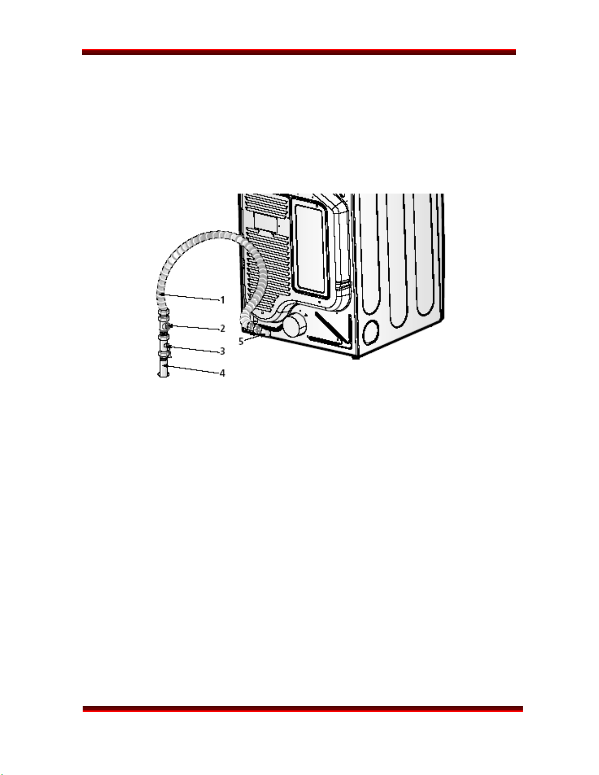
INSTALLATION (Makeup Air)
Minimum clearances must be observed, particularly if the dryer is installed in a closet or a
laundry alcove. The dryer is essentially an air pump moving 150 cfm (cubic feet per
minute) and that air must come from somewhere for the dryer to operate properly.
Additional air must be supplied to support proper combustion.
DLEX8388WM
Page 11
STEAM DRYER
TRAINING MANUAL
REAR FRONT
DLEX8377WM
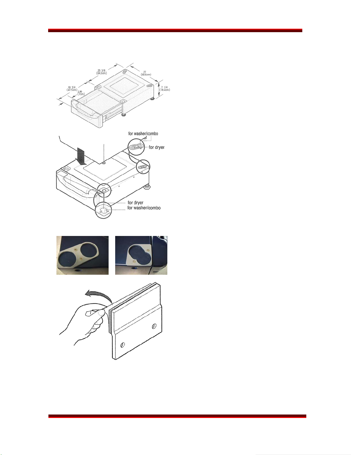
INSTALLATION (Pedestal)
For 27” Pedestals
(Washer, Dryer, and Combo)
Remove the pedestal, installation hardware,
and instructions from the shipping
container.
Level the pedestal on a solid, flat, level
floor. Lock down the rear adjusters, but
leave the front ones free for now.
Set the dryer on the pedestal and level it.
Level it and lock down all four adjusters on
the dryer.
Note which holes are for the washer and
which are for the dryer. If you are stacking
the appliances, the washer should be on
the bottom.
DLEX8388WM
Remove the protective paper from the
adhesive surface of the bracket.
Be particularly careful, because when this
adhesive makes contact, there is no
adjustment possible.
NOTE: Some kits include two sets of
brackets (curved for the dryer and flat
(shown) for the washer.) Use the correct
bracket for your application. The curved
bracket is for clearance of the exhaust vent
when a dryer has been converted to side
venting. (See next page.)
Page 12
STEAM DRYER
TRAINING MANUAL
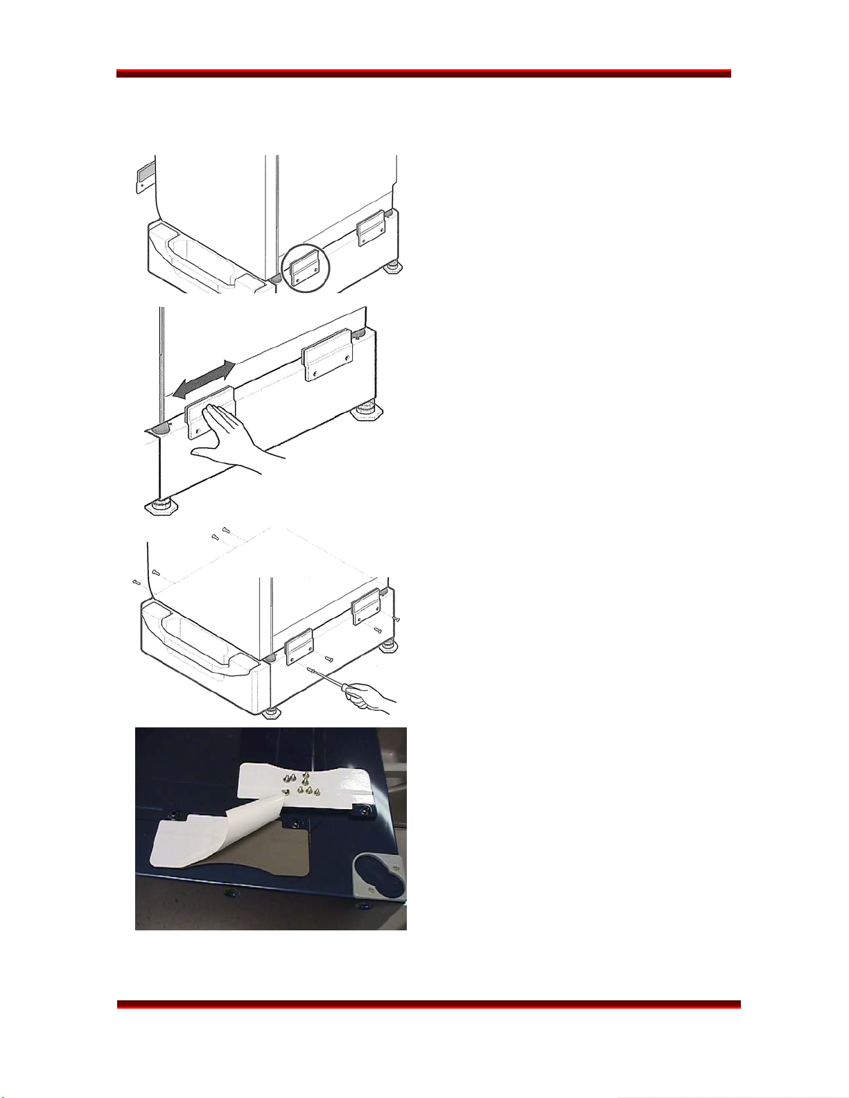
INSTALLATION (Pedestal) continued
Holding the adhesive part of the bracket
away from the dryer, insert the screws and
get them started.
Press the bracket onto the dryer and
tighten the screws.
Press the brackets onto the sides of the
dryer and rub the brackets from side to
side to ensure the total adhesive area is
attached completely.
Tighten all the screws securely.
DLEX8377WM
Lower each leg of the dryer one-fourth turn
with the adjusting wrench to put a little
pressure between the dryer and pedestal
to prevent any motion and rattling.
Push the dryer into place.
Check the level and adjust the front legs of
the pedestal as necessary. Then lock down
the adjusters.
The pedestal kit includes the mounting
plates (with adhesive covered by paper)
and the screws to attach the plates.
Remember, some pedestal kits come with
two sets of brackets. The flat tops are for
washers; the curved tops (shown) are for
dryers. Use the correct brackets for your
application. The curved bracket is for
clearance of the exhaust vent when a dryer
has been converted to side venting.
DLEX8388WM
Page 13
STEAM DRYER
TRAINING MANUAL
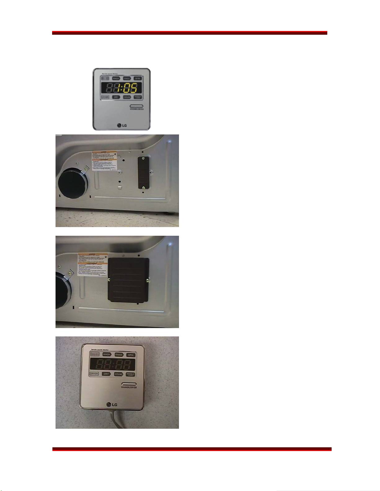
INSTALLATION (Modem and Monitor)
REMOTE MONITOR
The monitor plugs in to any 120 V
outlet in the home. It receives its data
signal via the power lines.
Be sure the dryer is unplugged.
Remove the modem cover.
Save the cover for future use; in the event
you must remove the modem, you can
replace the cover.
DLEX8377WM
AC
Attach the modem to the socket with the
screws provided.
Plug the monitor’s power cord in an outlet
where you can observe it easily. Use the
stand or the wall mount bracket.
Press and hold the button until the display
shows SET.
The dryer can be operated normally
without the modem if the customer does
not wish to purchase it as an option.
DLEX8388WM
Page 14
STEAM DRYER
TRAINING MANUAL
DLEX8377WM
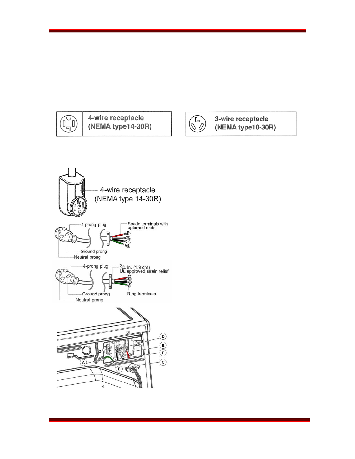
ELECTRICAL CONNECTION (Electric Dryer Only)
PIGTAIL INSTALLATION
Install the appropriate power cord for the outlet available. Grounding through the
neutral conductor is prohibited in new branch-circuits, mobile homes, recreational
vehicles, and where prohibited by local code.
4-wire Connection
The 4-wire receptacle looks like this.
Power cord with spade terminals.
Power cord with ring terminals.
Install a strain relief on the power cord.
Then connect the terminals to the terminal
block, matching the wire colors.
A. Ground screw on chassis
B. Green wire from power cord
C. Strain relief
D. Neutral screw on terminal block
E. Terminal block
F. Neutral wire from power cord
DLEX8388WM
Page 15
STEAM DRYER
TRAINING MANUAL
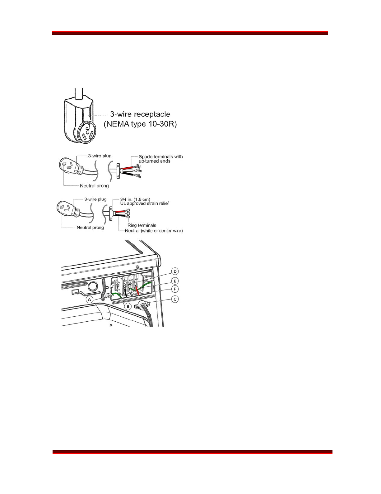
ELECTRICAL CONNECTION (Electric Dryer Only) continued
3-wire Connection
The 3-wire receptacle looks like this.
Power cord with spade terminals.
Power cord with ring terminals.
DLEX8377WM
Install a strain relief on the power cord.
Then connect the terminals to the terminal
block, matching the wire colors. Add a wire
to connect the chassis ground to neutral.
A. Ground screw on chassis
B. Green wire from power cord
C. Strain relief
D. Neutral screw on terminal block
E. Ground-to-neutral connection
F. Neutral wire from power cord
DLEX8388WM
Page 16
STEAM DRYER
TRAINING MANUAL
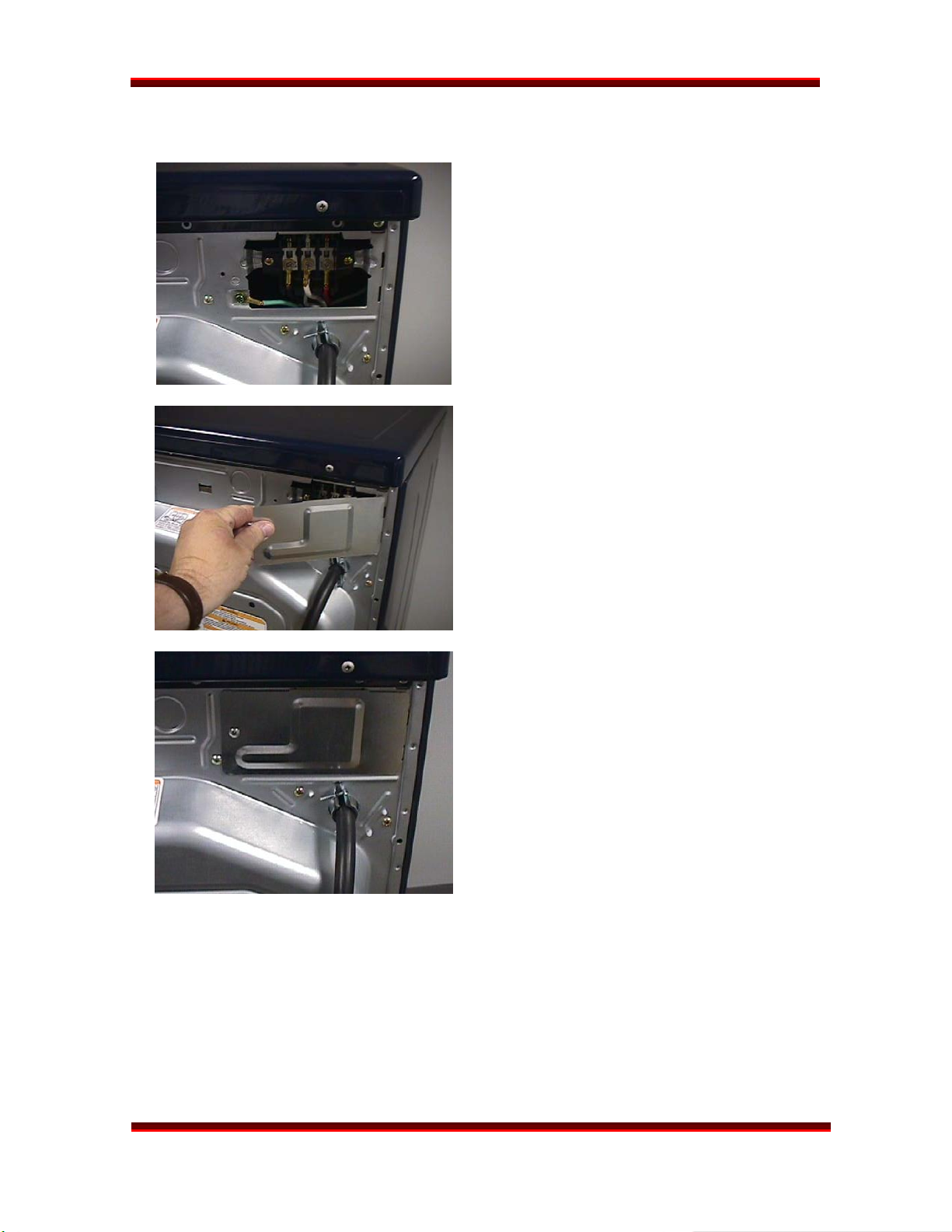
ELECTRICAL CONNECTION (Electric Dryer Only) continued
DLEX8377WM
Be sure to tighten all screws firmly, but do
not strip them or distort the contact area.
You want a secure connection without
damage to the connectors.
Be sure to install a strain relief on the
power cord.
Replace the terminal block cover by
inserting the tabs into the slots and letting
them slide down to engage.
Fold it over to the back of the dryer so it
covers the access to the terminal block. Be
sure no wires are exposed or could touch
any metal surface.
Secure the cover with a screw.
DLEX8388WM
Page 17
STEAM DRYER
TRAINING MANUAL
DLEX8377WM
GAS CONNECTION (Gas Dryer Only)
CAUTION! (This warning applies to both natural gas and propane.)
Gas is both flammable and explosive. Use caution when working with gas.
In most locations, installing and connecting gas is restricted to properly trained and
licensed persons.
Always inspect joints and connections for a leak with a soapy solution. If you see bubbles,
turn the gas off and open a window. If you smell gas, turn off the main valve and open a
window.
The gas dryer requires a 120 VAC, single-outlet, dedicated circuit. The cord is installed at
the factory and no user-intervention is required.
DLEX8388WM
Page 18
STEAM DRYER
TRAINING MANUAL
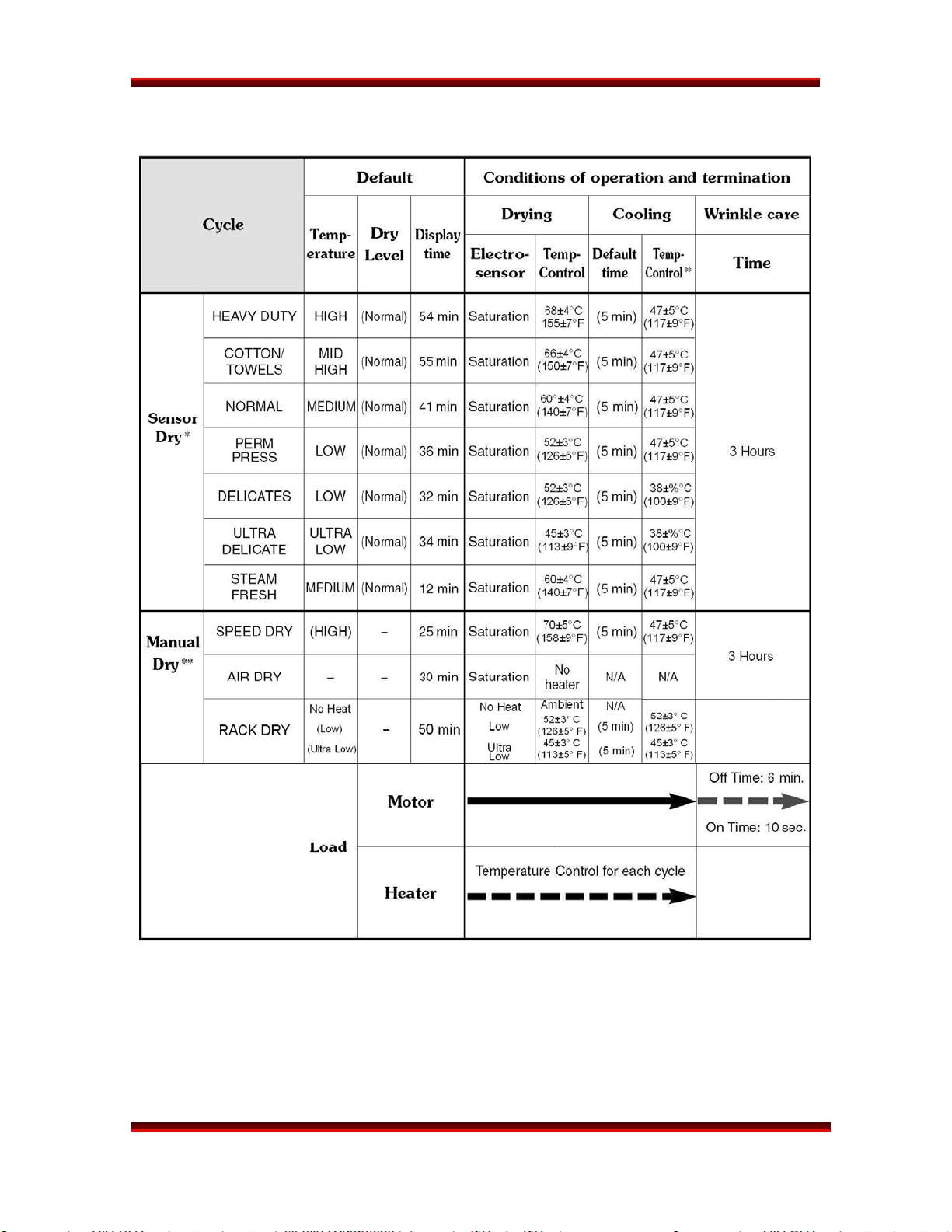
DRYER CYCLE CHART
DLEX8377WM
* SENSOR DRY The dryness level is set by the customer.
** MANUAL DRY The temperature is set by the customer. The maximum drying time
for RACK DRY or SPEED DRY is 1 hour 39 minutes.
The default settings can be overridden by the customer in most cases.
DLEX8388WM
Page 19
STEAM DRYER

TRAINING MANUAL
DLEX8377WM
STEAM CYCLE INFORMATION
The steam dryer is designed to provide the power of steam through the introduction of
steam into almost every drying cycle.
STEAMFRESH™
The STEAMFRESH™ cycle is a 20-minute cycle that tumbles the clothes in a spray of
steam. This cycle is NOT a wash cycle, but is instead designed to refresh clothing that
has been packed away, stored, or otherwise wrinkled and less than freshly laundered. The
steam cycle will refresh from one to five items during its 20-minute run time. The drum
tumbles the clothes while steam sprays through them for the first five minutes. Then the
steam continues while the drum tumbles for 2 seconds once each minute. At that point
(12 minutes in to the cycle,) the steam generator is turned off and the dryer continues
to tumble constantly with the main heater engaged to finish drying the clothes. The main
heater is turned off for the last two minutes of the cycle while the drum continues to
tumble to allow the clothes to cool.
The MORE TIME and LESS TIME buttons are used to adjust the number of items to be
freshened during the STEAMFRESH™ cycle.
The time cannot be adjusted by the user when a sensor dry cycle is engaged.
REDUCE STATIC
The REDUCE STATIC cycle is an add-on to all the regular cycles except AIR DRY or
RACK DRY. When REDUCE STATIC is selected, the main heater is turned off two minutes
before the end of the cycle and the steam generator is energized for the final two
minutes while the drum continues to turn.
EASY IRON
The EASY IRON cycle is an add-on to all the regular cycles except AIR DRY or RACK DRY.
When EASY IRON is selected, the main heater is turned off eight minutes before the end
of the cycle and the steam generator is energized for the final eight minutes while the
drum tumbles for two seconds once a minute.
CHILD LOCK can be engaged only after a cycle has been selected and the START button
has been pressed. CHLD LOCK locks ALL controls, including the POWER button. It
releases at the end of the cycle or in the event of a power failure.
DLEX8388WM
Page 20
STEAM DRYER
TRAINING MANUAL
DLEX8377WM
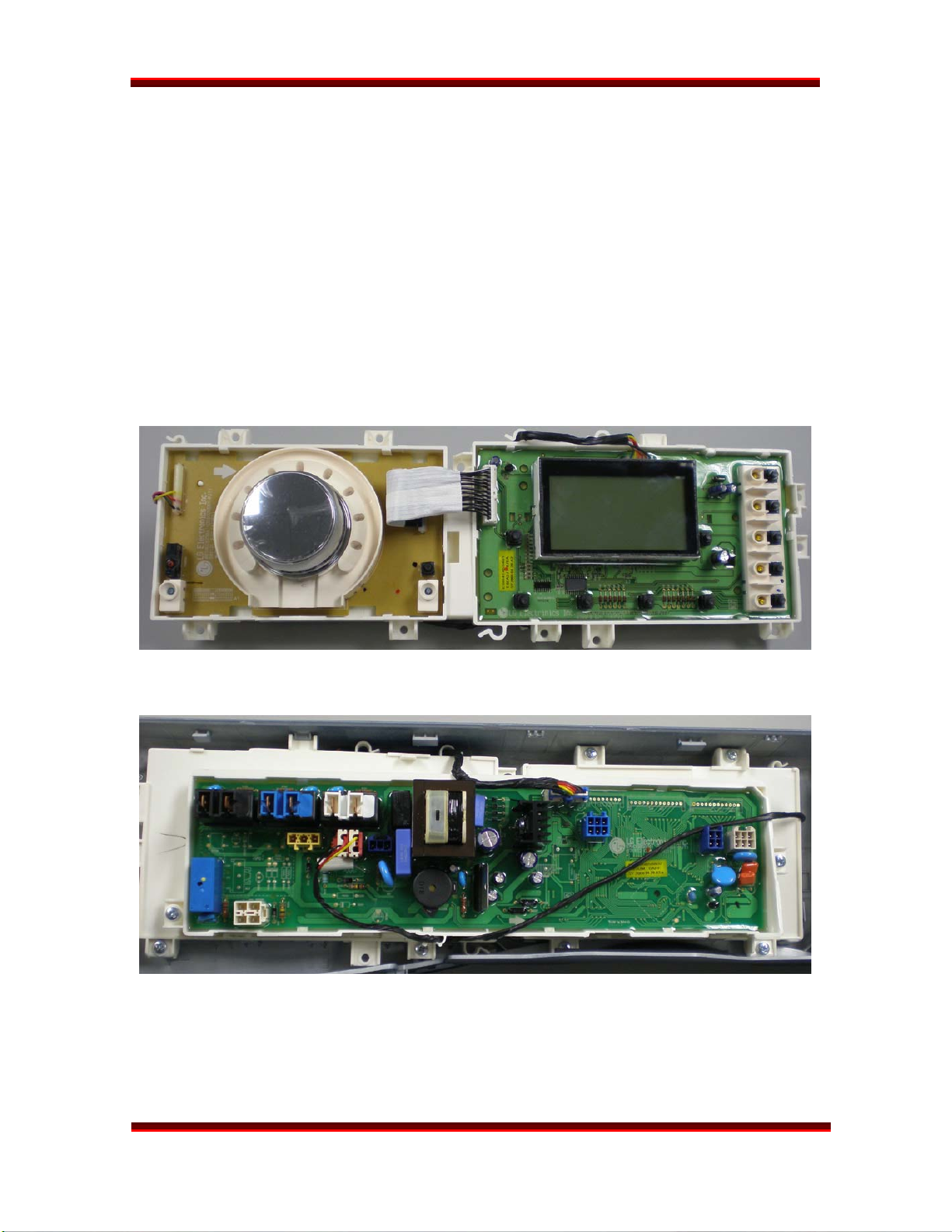
DISPLAY PWB
The display board is actually two boards connected by a ribbon cable. One board holds
the selector knob and cycle indicator LEDs. The other holds the LCD display and
adjustment buttons to override the pre-set cycle selections.
DISPLAY BOARD
The display board includes the LCD display and LEDs that indicate the various cycle and
option information. It is made of two boards that are permanently connected by a ribbon
cable that is soldered to the board at each end. This makes the boards a single unit. The
purpose is to allow the display board to flex to fit inside a curved control panel while
maintaining its integrity as a single board.
MAIN CONTROL BOARD
The main board is attached to the back of the display board in the control panel by two
screws. Many of the components of the dryer can be tested by removing their connector
at the main board.
DLEX8388WM
Page 21
STEAM DRYER
TRAINING MANUAL
DLEX8377WM
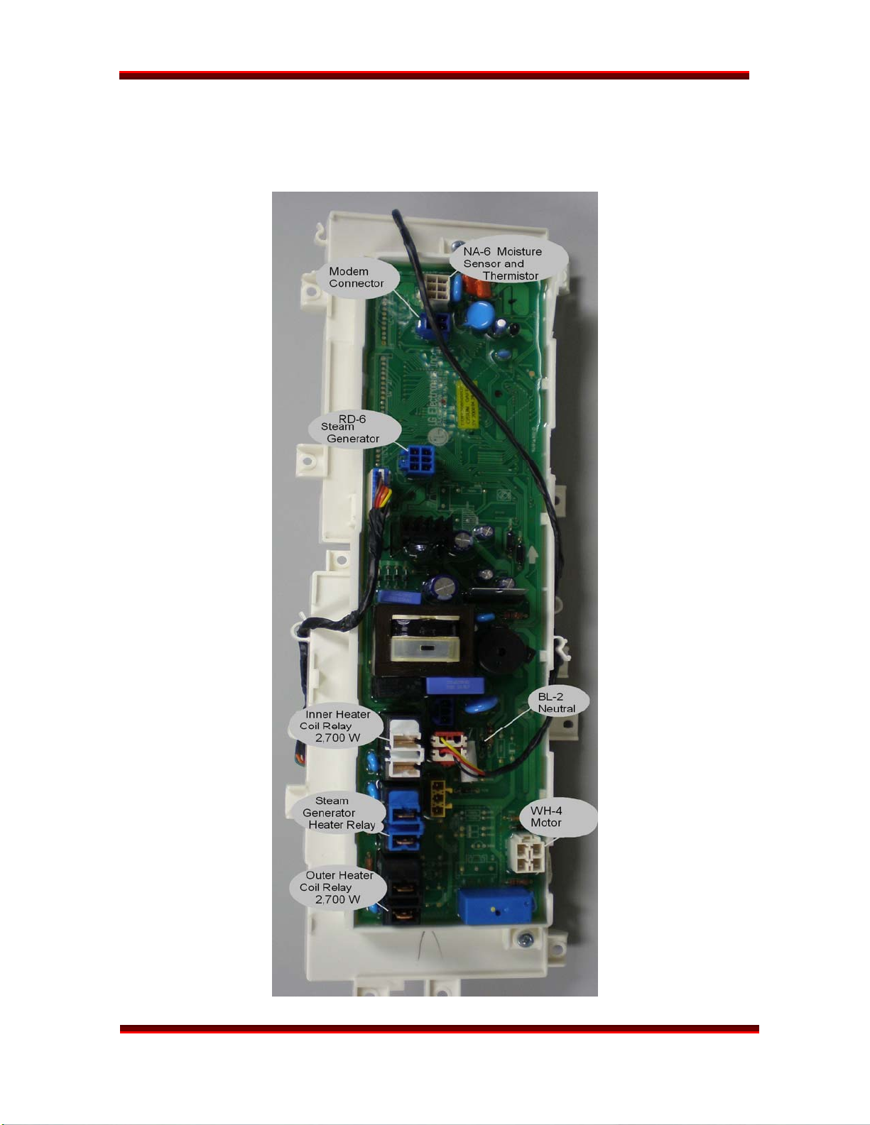
MAIN PWB
The main board includes the relays that operate electric heaters and gas valves.
The gas and electric models have a different main board.
DLEX8388WM
Page 22
STEAM DRYER
TRAINING MANUAL
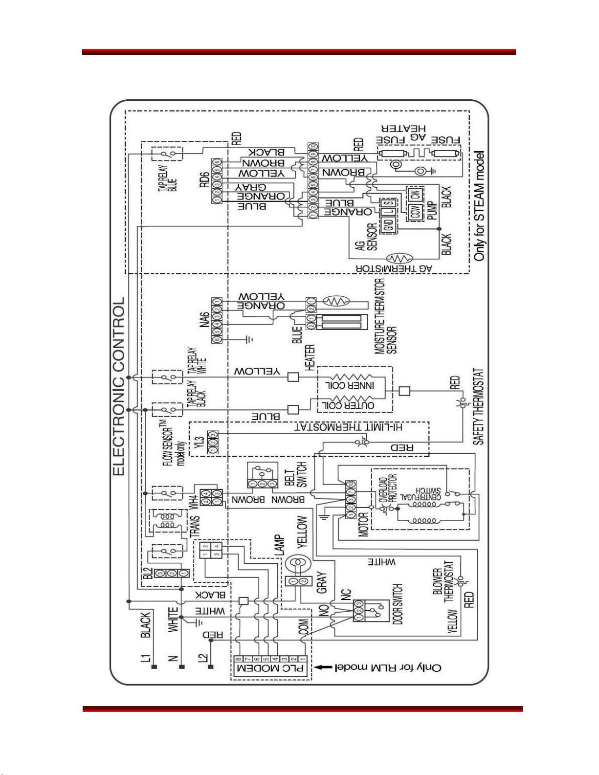
SCHEMATIC – ELECTRIC DRYER
DLEX8377WM
DLEX8388WM
Page 23
STEAM DRYER
TRAINING MANUAL
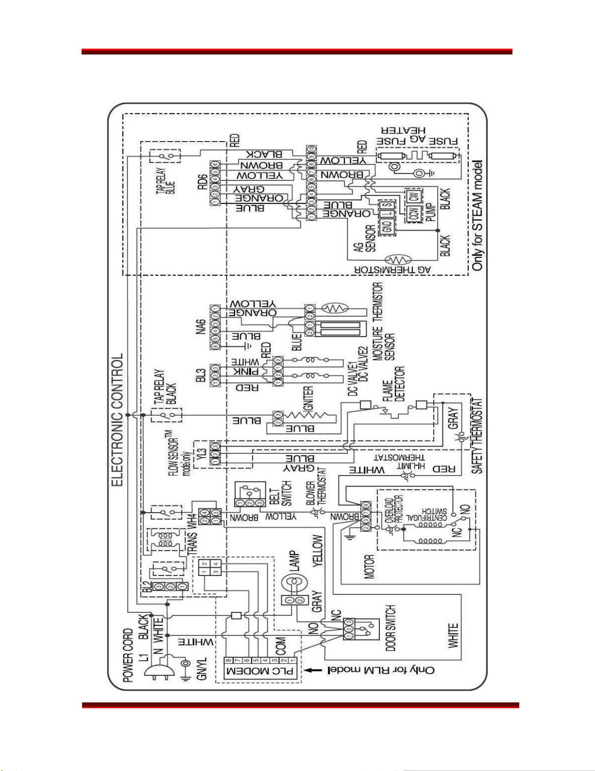
SCHEMATIC – GAS DRYER
DLEX8377WM
DLEX8388WM
Page 24
STEAM DRYER
 Loading...