How it Works
Log In / Sign Up
Buy Points
How it Works
FAQ
Contact Us
Questions and Suggestions
Users
LG
Loading...
D
DLEX3370W
4
DLEX3370W/00
Dlex3470
3
DLEX3470V
4
DLEX3470W
3
DLEX3550
2
DLEX3550V
5
DLEX3550W
5
DLEX3570
4
DLEX3570V
4
DLEX3570W
4
DLEX3650V
2
DLEX3700
2
DLEX3700V/00
DLEX3700W
DLEX3700W/00
DLEX3875
3
DLEX3875V
6
DLEX3875W
5
DLEX3885
4
DLEX3885C
5
DLEX3885W
3
DLEX3900
2
DLEX3900B
2
DLEX3900W
2
DLEX4000
DLEX4000B
DLEX4000W
DLEX4070
2
DLEX4070 Series
DLEX4070V
6
DLEX4070W
4
DLEX4200B
2
DLEX4200W
DLEX4270
4
dlex4270v
5
DLEX4270W
4
DLEX4370
2
DLEX4370K
3
DLEX4370K/00
DLEX4370W
DLEX4370W/00
DLEX4500B
DLEX5000
DLEX5000V
4
DLEX5000W
3
DLEX5101
2
DLEX5101V
11
DLEX5101W
8
DLEX5170
3
DLEX5170V
6
DLEX5170W
5
DLEX5175W
DLEX5680
DLEX5680V
5
DLEX5680VE/00
DLEX5680W
4
DLEX5780E
DLEX5780VE
4
DLEX5780WE
5
DLEX5955W
DLEX6001V
4
DLEX6001W
2
DLEX7177
DLEX7177RM
5
DLEX7177SM
DLEX7177WM
4
DLEX7200
DLEX7200W
DLEX7250*
DLEX7300VE
DLEX7600
DLEX7600E
DLEX7600KE
2
DLEX7600VE
3
DLEX7600WE
DLEX7700E
3
DLEX7700KE
2
DLEX7700VE
2
DLEX7700WE
DLEX7710VE
2
DLEX7800
DLEX7800VE
2
DLEX7800WE
2
DLEX7900BE
3
DLEX7900VE
DLEX8000
2
DLEX8000V
8
Dlex8000W
7
DLEX800V
DLEX800W
DLEX8100V
3
DLEX8100V/00
DLEX8100W
2
DLEX8377
2
DLEX8377CM
2
DLEX8377NM
4
DLEX8377RM
3
DLEX8377WM
6
DLEX8388WM
Loading...
Loading...
Nothing found
DLEX5170V
Installation Manual
2 pgs
3.24 Mb
0
Owner's manual
88 pgs
44.03 Mb
0
Owners Manual
88 pgs
6.89 Mb
0
Owner’s Manual
80 pgs
43.23 Mb
0
Service Manual
50 pgs
8.71 Mb
0
Specifications
2 pgs
1.11 Mb
0
Table of contents
Loading...
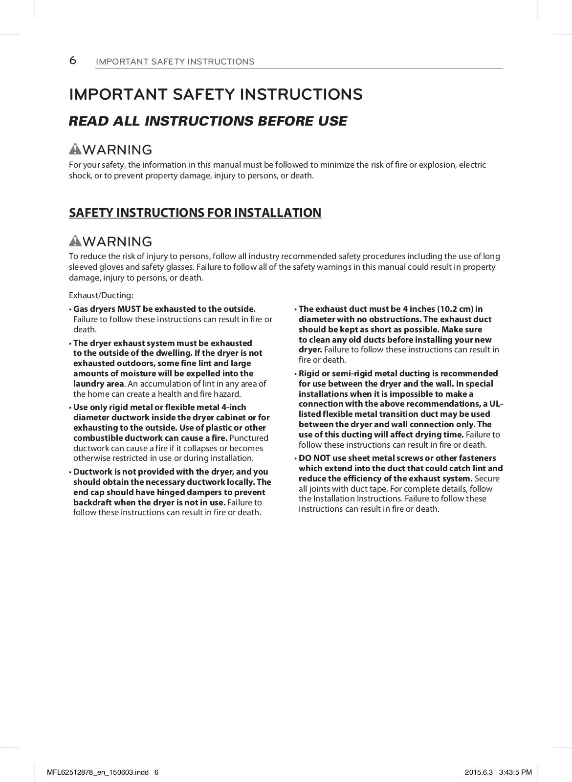
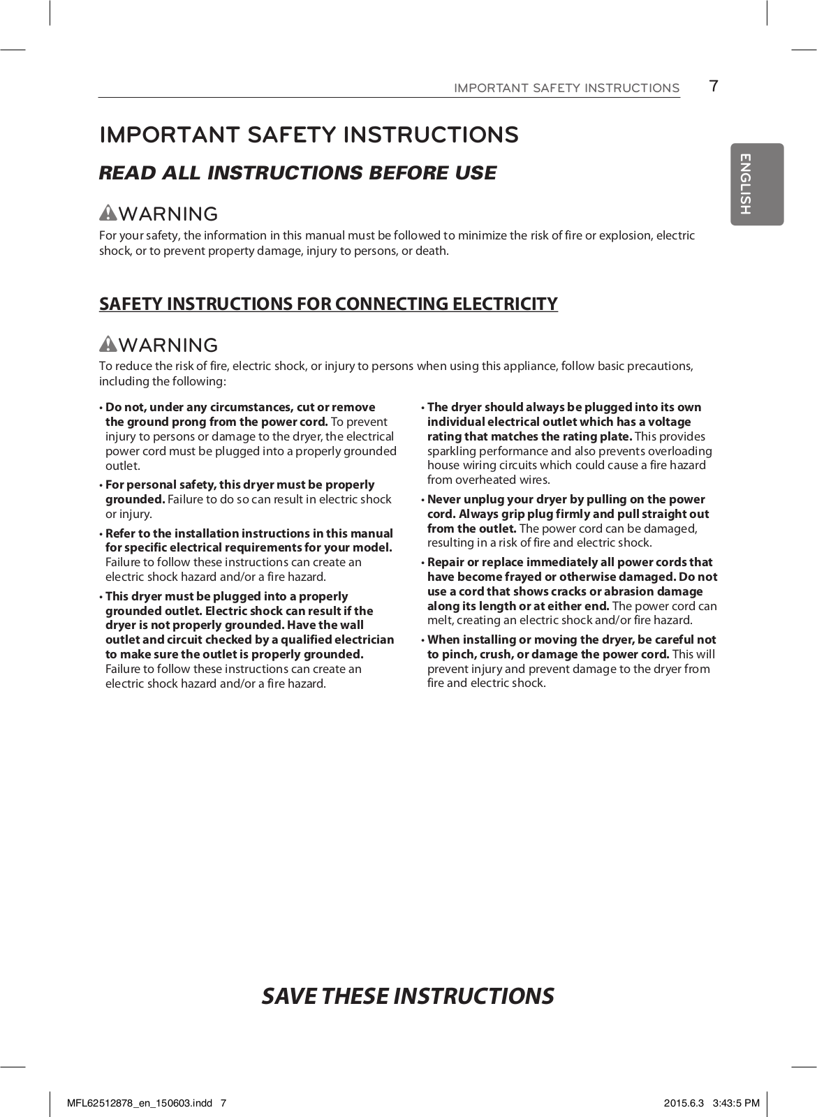
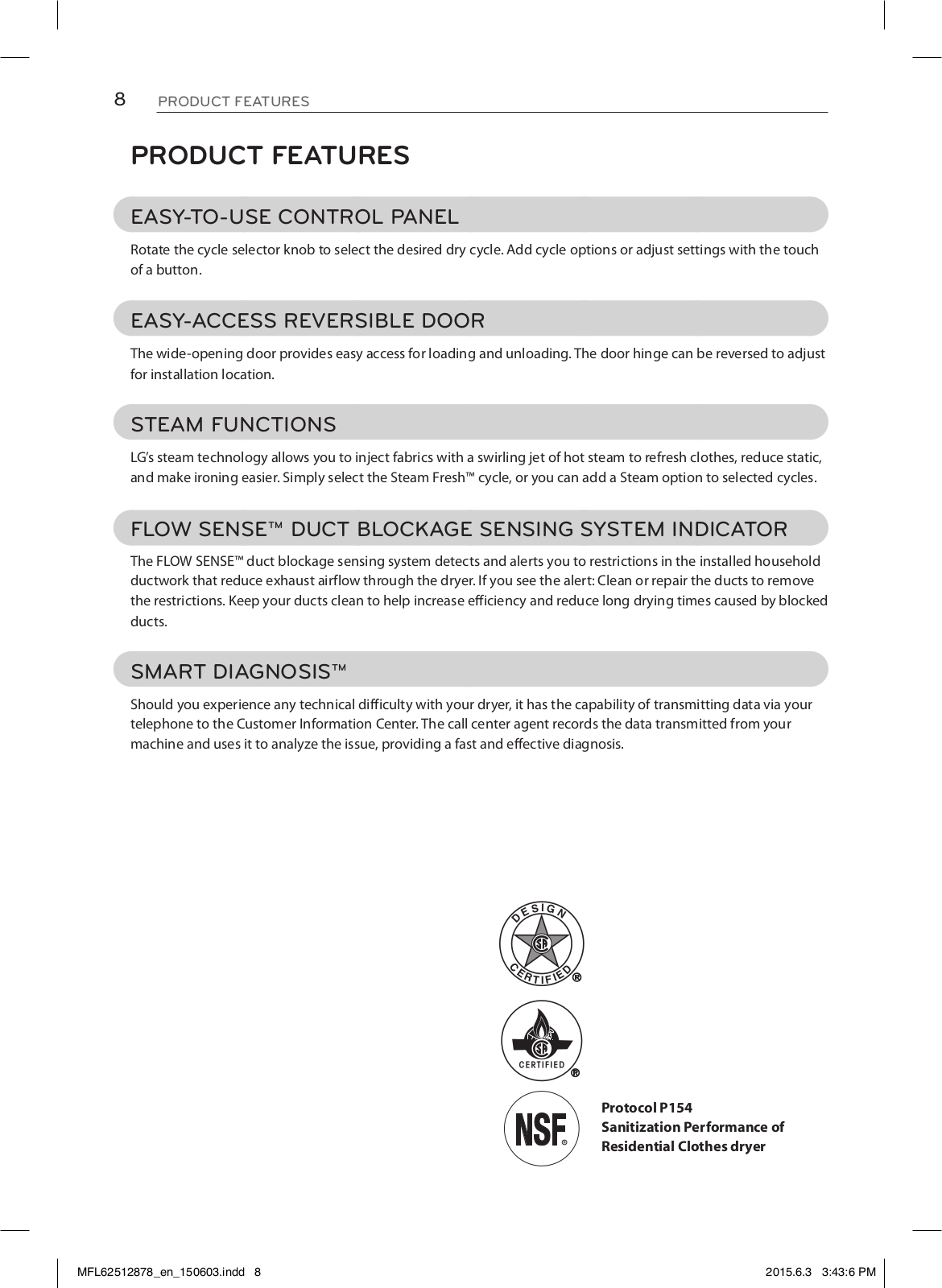
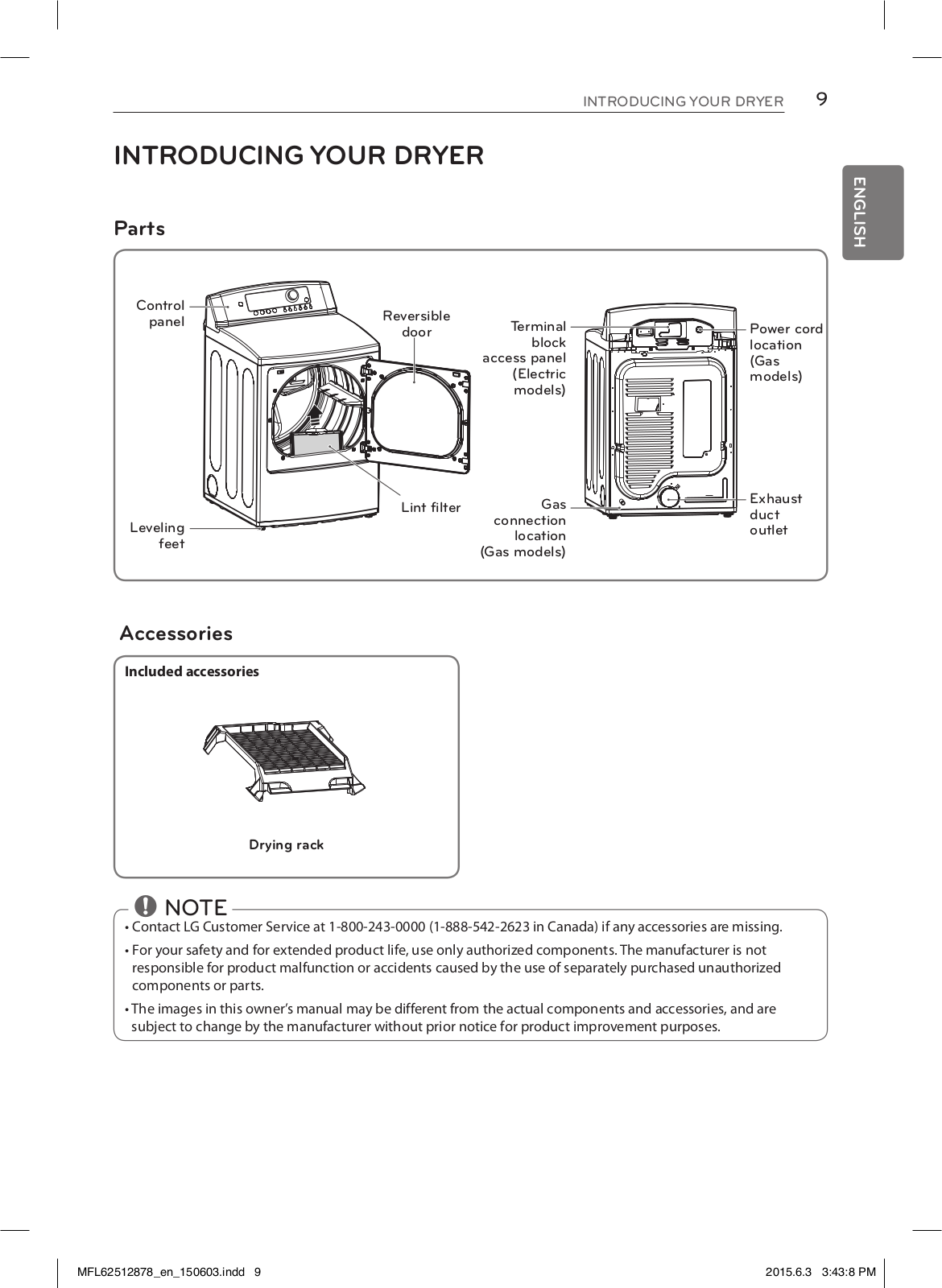
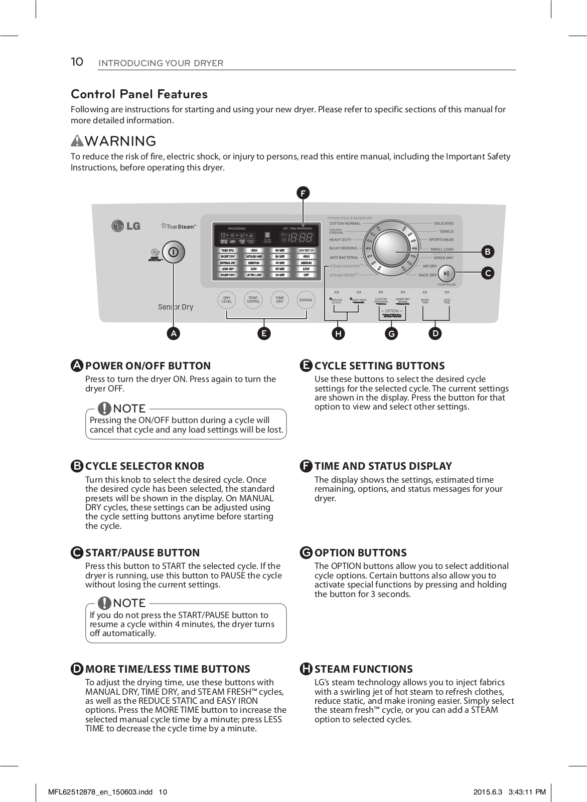
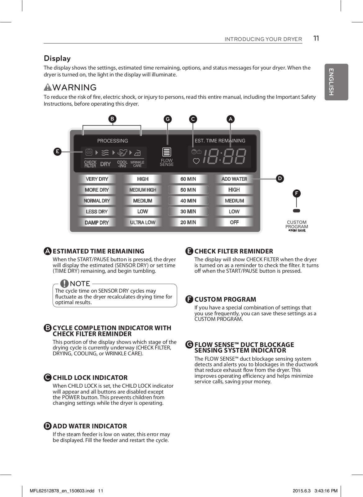
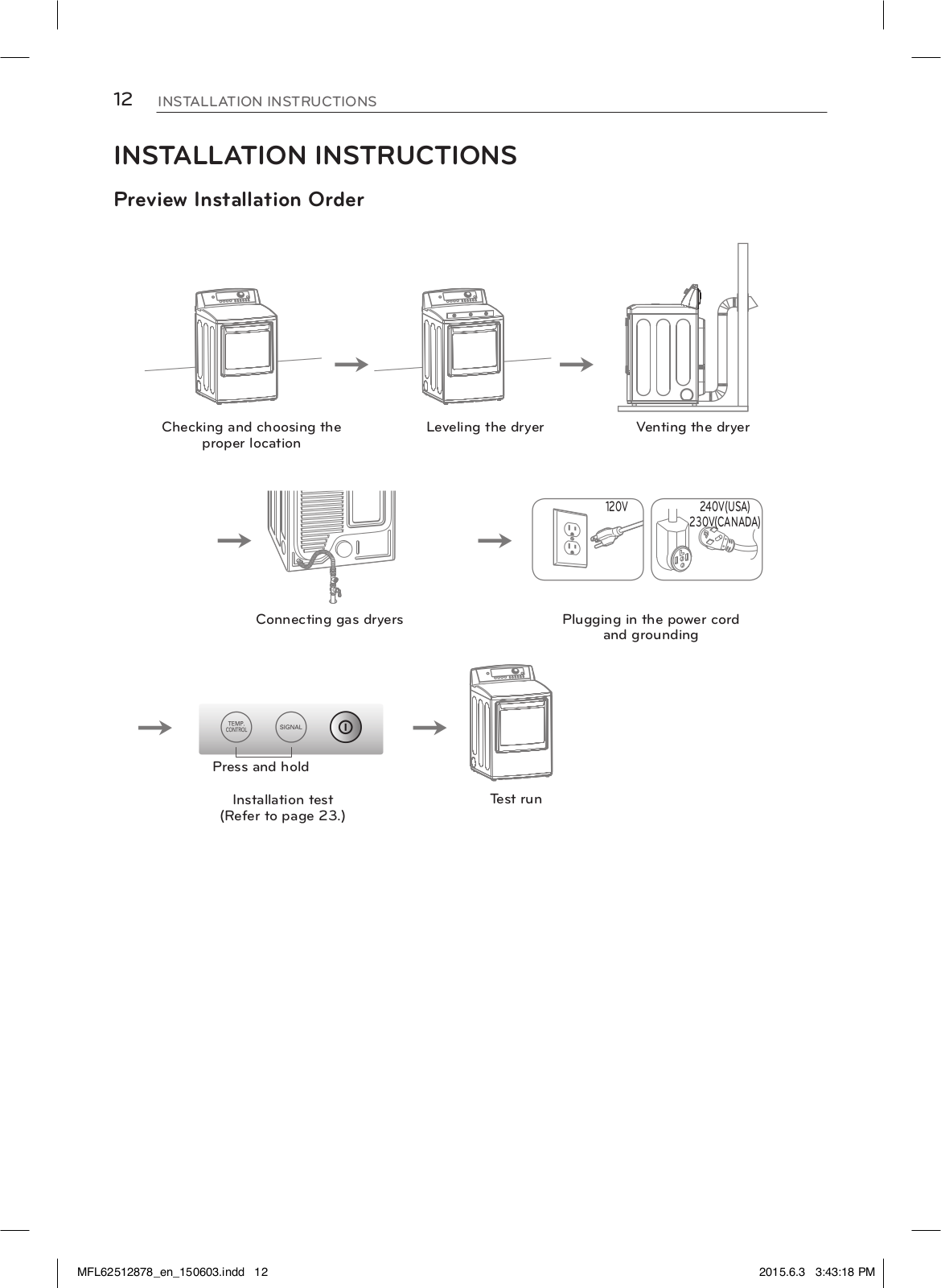
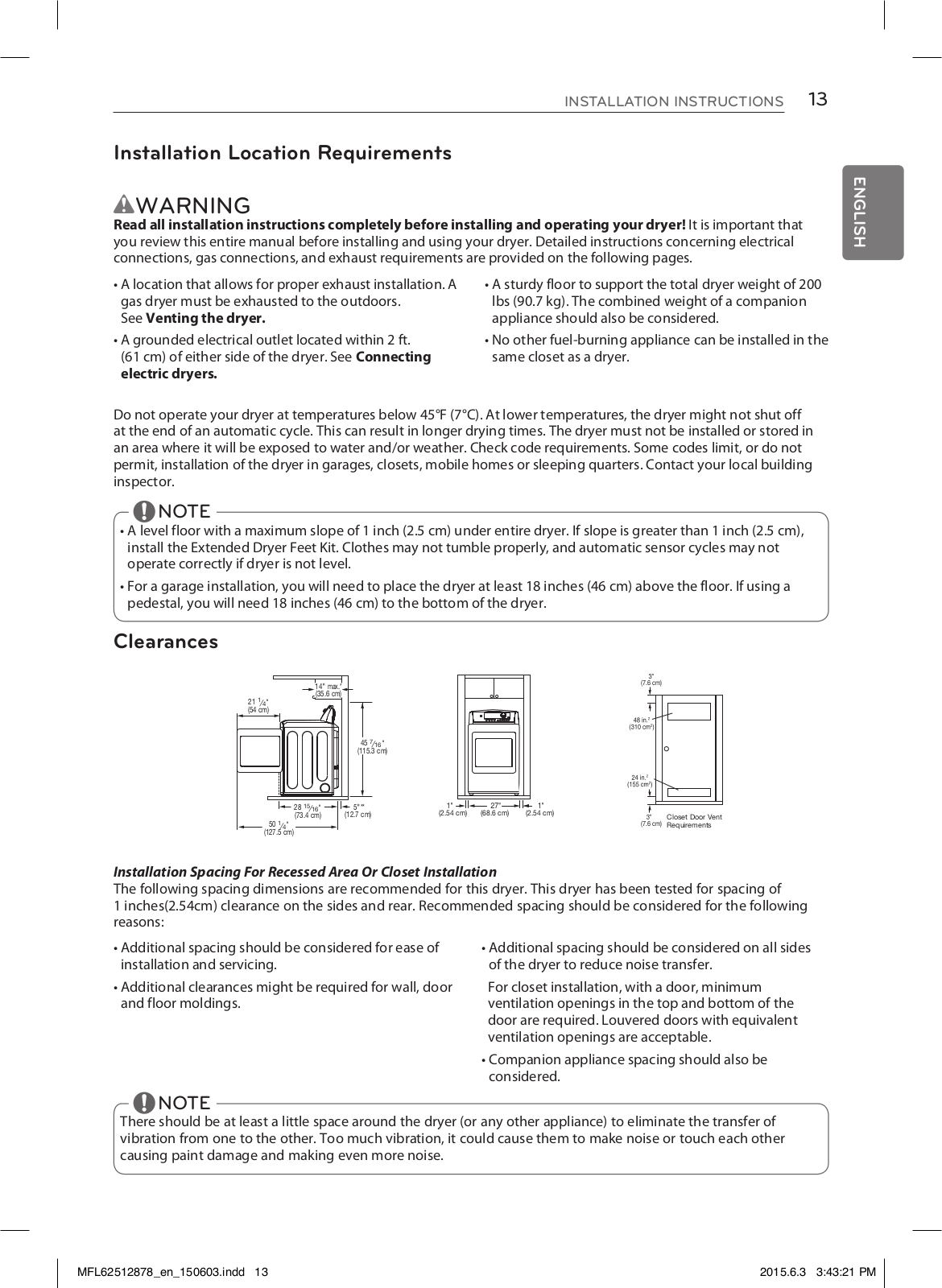
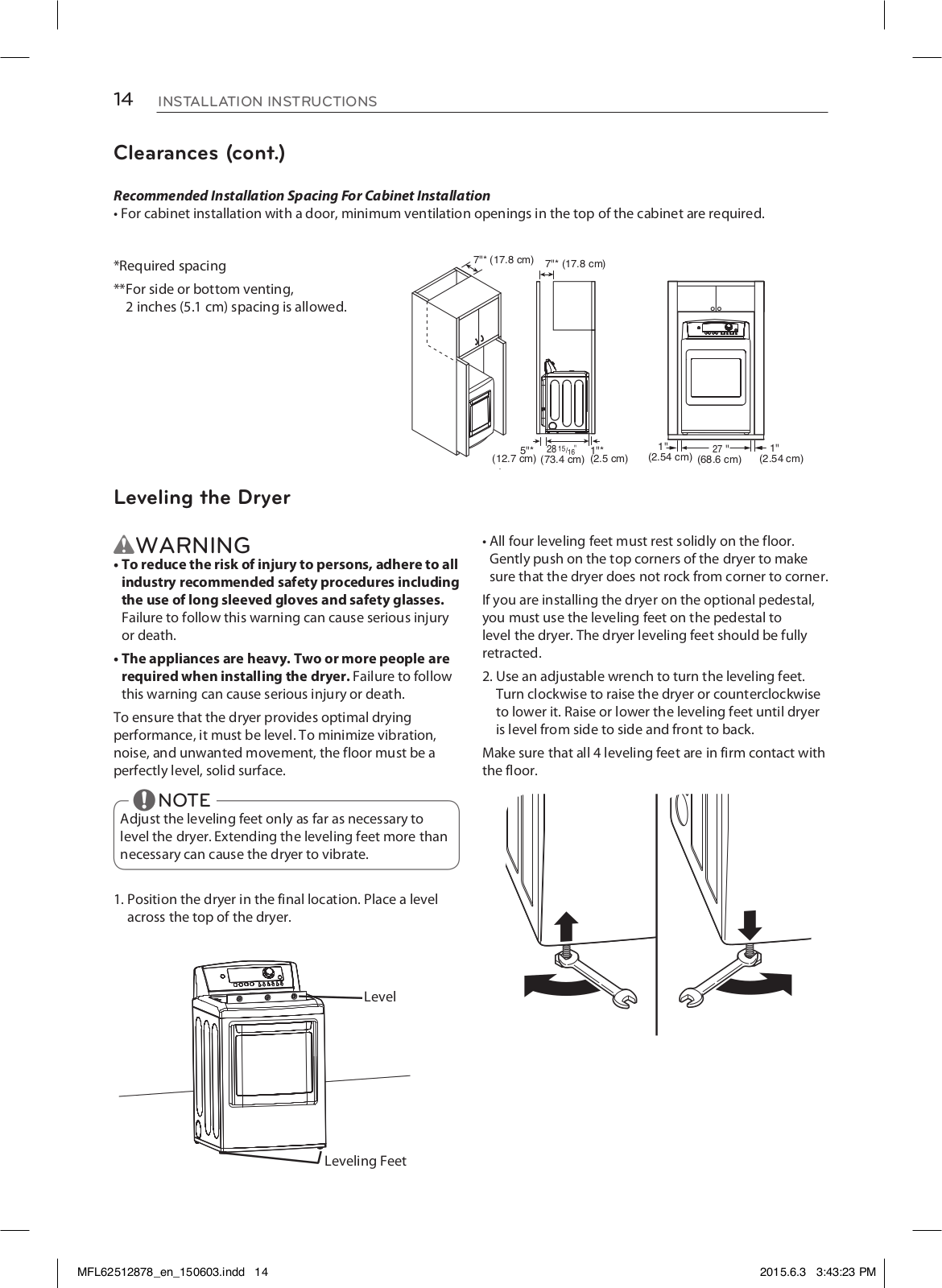
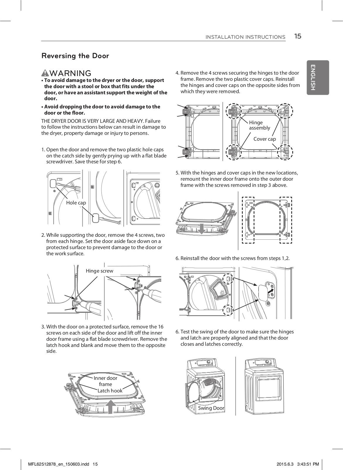
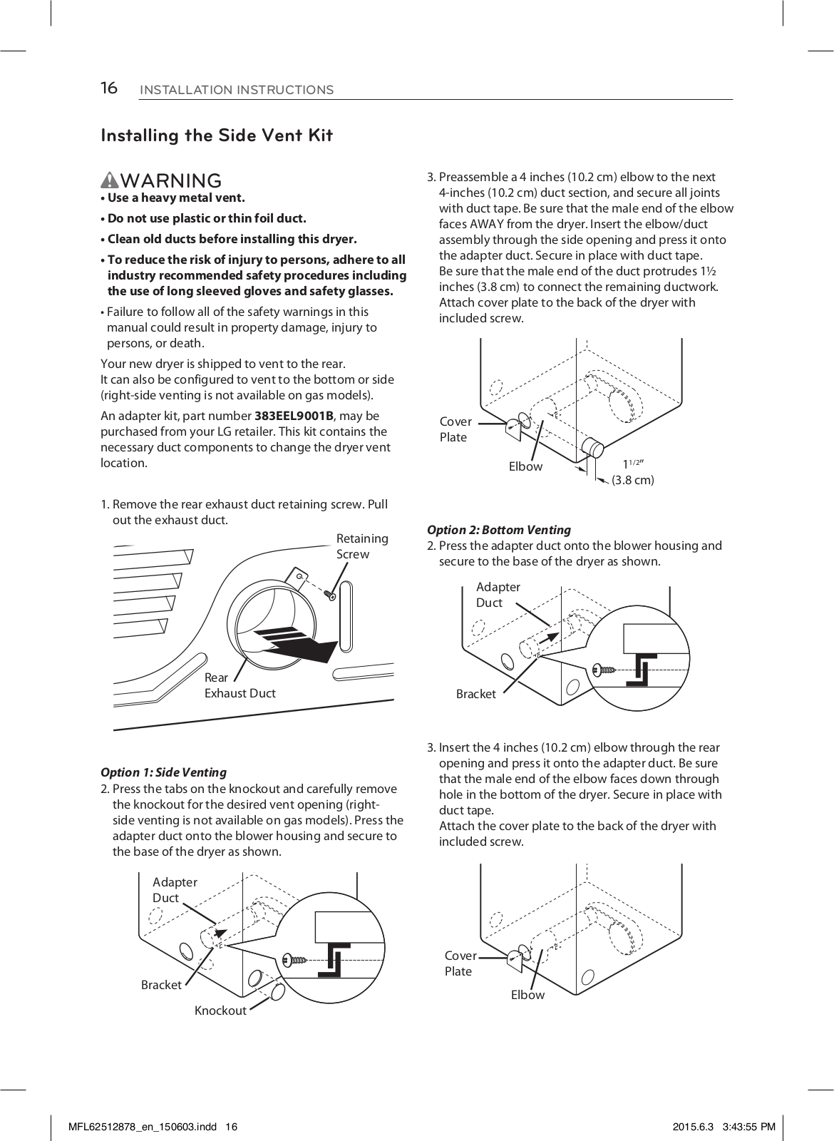
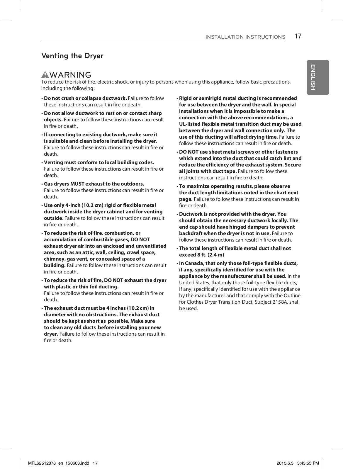
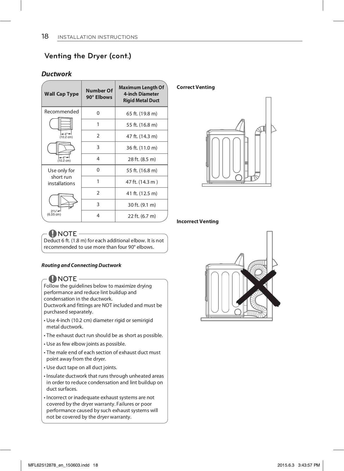
LG DLEX5170V, DLGX5171V, DLEX5175W Owner’s Manual
...
LG Owner’s Manual
Download
Specifications and Main Features
Frequently Asked Questions
User Manual
Download
Loading...
+
56
hidden pages
Unhide
You need points to download manuals.
1 point = 1 manual.
You can buy points or you can get point for every manual you upload.
Buy points
Upload your manuals
 Loading...