

Page 1
DJ MIXER
DJM-3000
ORDER NO.
RRV2587
DJM-3000
THIS MANUAL IS APPLICABLE TO THE FOLLOWING MODEL(S) AND TYPE(S).
Model Type Porew Requirement
DJM-3000 KUCXCN AC120V
DJM-3000 WYXCN AC220-240V
DJM-3000 RLBXCN AC110-120V/220-240V With the voltage selector
The voltage can be converted by the
following method.
www.electronicsrepair.net
For details, refer to "Important symbols for good services" on the next page.
T-ZZR APR.2002.printed in Japan
Page 2
1234
SAFTY INFORMATION
A
This service manual is intended for qualified service technicians; it is not meant for the casual
do-it-yourselfer. Qualified technicians have the necessary test equipment and tools, and have been
trained to properly and safely repair complex products such as those covered by this manual.
Improperly performed repairs can adversely affect the safety and reliability of the product and may
void the warranty. If you are not qualified to perform the repair of this product properly and safely, you
should not risk trying to do so and refer the repair to a qualified service technician.
WARNING
This product contains lead in solder and certain electrical parts contain chemicals which are known to the state of California to
B
cause cancer, birth defects or other reproductive harm.
Health & Safety Code Section 25249.6 – Proposition 65
NOTICE
(FOR CANADIAN MODEL ONLY)
Fuse symbols (fast operating fuse) and/or (slow operating fuse) on PCB indicate that replacement
parts must be of identical designation.
REMARQUE
(POUR MODÈLE CANADIEN SEULEMENT)
Les symboles de fusible (fusible de type rapide) et/ou (fusible de type lent) sur CCI indiquent que
C
les pièces de remplacement doivent avoir la même désignation.
(FOR USA MODEL ONLY)
1. SAFETY PRECAUTIONS
The following check should be performed for the
continued protection of the customer and service
technician.
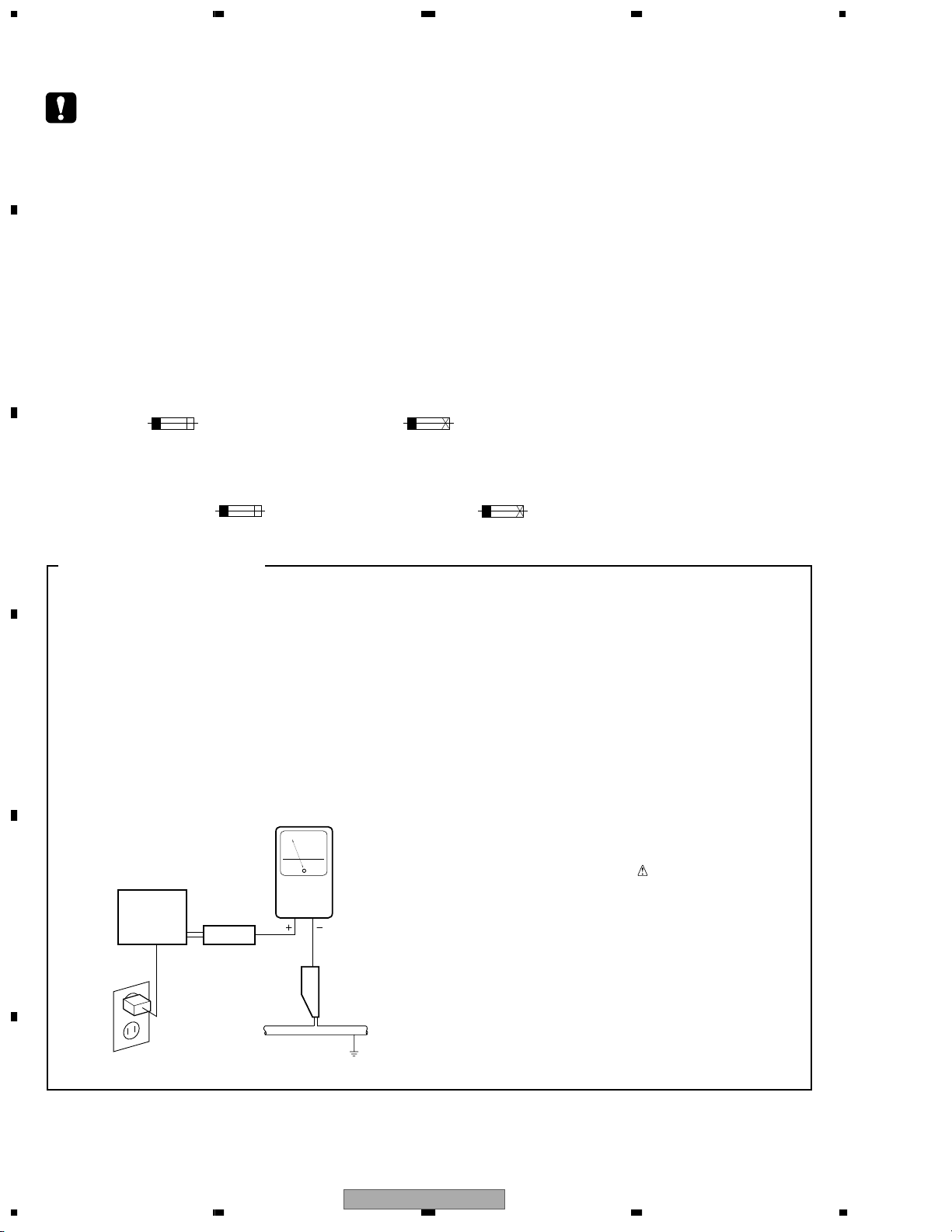
LEAKAGE CURRENT CHECK
Measure leakage current to a known earth ground
(water pipe, conduit, etc.) by connecting a leakage
D
E
current tester such as Simpson Model 229-2 or
equivalent between the earth ground and all exposed
metal parts of the appliance (input/output terminals,
screwheads, metal overlays, control shaft, etc.). Plug
the AC line cord of the appliance directly into a 120V
AC 60 Hz outlet and turn the AC power switch on. Any
current measured must not exceed 0.5 mA.
Reading should
not be above
0.5 mA
Earth
ground
Device
under
test
Also test with
plug reversed
(Using AC adapter
plug as required)
Test all
exposed metal
surfaces
Leakage
current
tester
AC Leakage Test
ANY MEASUREMENTS NOT WITHIN THE
LIMITS OUTLINED ABOVE ARE INDICATIVE
OF A POTENTIAL SHOCK HAZARD AND
MUST BE CORRECTED BEFORE RETURNING THE APPLIANCE TO THE CUSTOMER.
2. PRODUCT SAFETY NOTICE
Many electrical and mechanical parts in the appliance
have special safety related characteristics. These are
often not evident from visual inspection nor the
protection afforded by them necessarily can be obtained
by using replacement components rated for voltage,
wattage, etc. Replacement parts which have these
special safety characteristics are identified in this
Service Manual.
Electrical components having such features are
identified by marking with a
on the parts list in this Service Manual.
The use of a substitute replacement component which
does not have the same safety characteristics as the
PIONEER recommended replacement one, shown in the
parts list in this Service Manual, may create shock, fire,
or other hazards.
Product Safety is continuously under review and new
instructions are issued from time to time. For the latest
information, always consult the current PIONEER
Service Manual. A subscription to, or additional copies
of, PIONEER Service Manual may be obtained at a
nominal charge from PIONEER.
on the schematics and
F
2
1234
DJM-3000
Page 3
5678
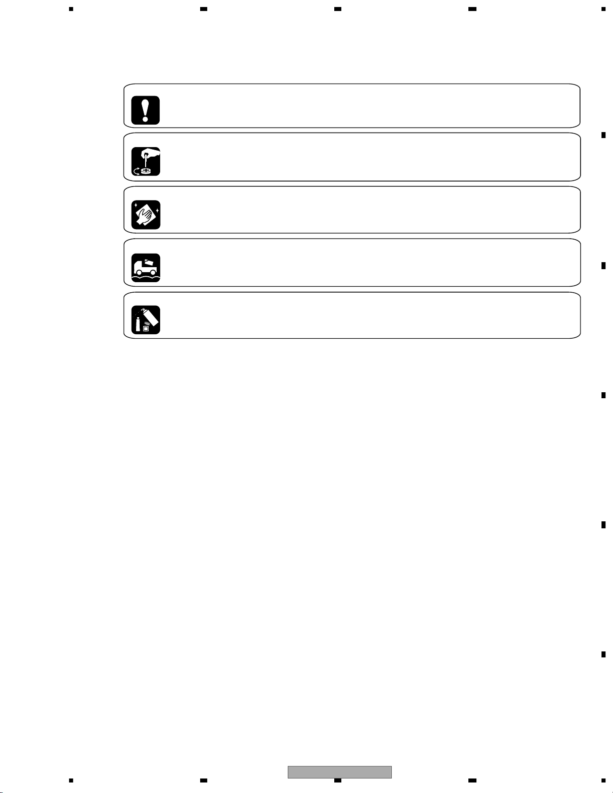
[ Important symbols for good services ]
In this manual, the symbols shown-below indicate that adjustments, settings or cleaning should be made securely.
When you find the procedures bearing any of the symbols, be sure to fulfill them:
A
1. Product safety
You should conform to the regulations governing the product (safety, radio and noise, and other regulations), and
should keep the safety during servicing by following the safety instructions described in this manual.
2. Adjustments
To keep the original performances of the product, optimum adjustments or specification confirmation is indispensable.
In accordance with the procedures or instructions described in this manual, adjustments should be performed.
3. Cleaning
For optical pickups, tape-deck heads, lenses and mirrors used in projection monitors, and other parts requiring cleaning,
proper cleaning should be performed to restore their performances.
4. Shipping mode and shipping screws
To protect the product from damages or failures that may be caused during transit, the shipping mode should be set or
the shipping screws should be installed before shipping out in accordance with this manual, if necessary.
5. Lubricants, glues, and replacement parts
Appropriately applying grease or glue can maintain the product performances. But improper lubrication or applying
glue may lead to failures or troubles in the product. By following the instructions in this manual, be sure to apply the
prescribed grease or glue to proper portions by the appropriate amount.For replacement parts or tools, the prescribed
ones should be used.
B
C
D
56
DJM-3000
E
F
7
8
3
Page 4

1234
CONTENTS
SAFTY INFORMATION . . . . . . . . . . . . . . . . . . . . . . . . . . . . . . . . . . . . . . . . . . . . . 2
A
B
C
D
E
F
1. SPECIFICATIONS . . . . . . . . . . . . . . . . . . . . . . . . . . . . . . . . . . . . . . . . . . . . . . .5
2. EXPLODED VIEWS AND PARTS LIST . . . . . . . . . . . . . . . . . . . . . . . . . . . . . . . . . . . .6
2.1 PACKING . . . . . . . . . . . . . . . . . . . . . . . . . . . . . . . . . . . . . . . . . . . . . . . . . 6
2.2 EXTERIOR(1/2) SECTION . . . . . . . . . . . . . . . . . . . . . . . . . . . . . . . . . . . . . . . .8
2.3 EXTERIOR(2/2) SECTION . . . . . . . . . . . . . . . . . . . . . . . . . . . . . . . . . . . . . . . 10
3. BLOCK DIAGRAM AND SCHEMATIC DIAGRAM . . . . . . . . . . . . . . . . . . . . . . . . . . . . . . 12
3.1 BLOCK DIAGRAM . . . . . . . . . . . . . . . . . . . . . . . . . . . . . . . . . . . . . . . . . . . . 12
3.2 OVERALL WIRING CONNECTION DIAGRAM . . . . . . . . . . . . . . . . . . . . . . . . . . . . . 14
3.3 TERMA(1/3) ASSY. . . . . . . . . . . . . . . . . . . . . . . . . . . . . . . . . . . . . . . . . . . . 16
3.4 TERMA(2/3) ASSY. . . . . . . . . . . . . . . . . . . . . . . . . . . . . . . . . . . . . . . . . . . . 18
3.5 TERMA(3/3) ASSY. . . . . . . . . . . . . . . . . . . . . . . . . . . . . . . . . . . . . . . . . . . . 20
3.6 TERMB(1/4) ASSY. . . . . . . . . . . . . . . . . . . . . . . . . . . . . . . . . . . . . . . . . . . . 22
3.7 TERMB(2/4) ASSY. . . . . . . . . . . . . . . . . . . . . . . . . . . . . . . . . . . . . . . . . . . . 24
3.8 TERMB(3/4) ASSY. . . . . . . . . . . . . . . . . . . . . . . . . . . . . . . . . . . . . . . . . . . . 26
3.9 TERMB(4/4) ASSY. . . . . . . . . . . . . . . . . . . . . . . . . . . . . . . . . . . . . . . . . . . . 28
3.10 VR(1/8) ASSY . . . . . . . . . . . . . . . . . . . . . . . . . . . . . . . . . . . . . . . . . . . . . 30
3.11 VR(2/8) and HP ASSY . . . . . . . . . . . . . . . . . . . . . . . . . . . . . . . . . . . . . . . . . 32
3.12 VR(3/8) ASSY . . . . . . . . . . . . . . . . . . . . . . . . . . . . . . . . . . . . . . . . . . . . . 34
3.13 VR(4/8) ASSY . . . . . . . . . . . . . . . . . . . . . . . . . . . . . . . . . . . . . . . . . . . . . 36
3.14 VR(5/8) ASSY . . . . . . . . . . . . . . . . . . . . . . . . . . . . . . . . . . . . . . . . . . . . . 38
3.15 VR(6/8), CF and CFCURV ASSYS ASSY . . . . . . . . . . . . . . . . . . . . . . . . . . . . . . . 40
3.16 VR(7/8) ASSY . . . . . . . . . . . . . . . . . . . . . . . . . . . . . . . . . . . . . . . . . . . . . 42
3.17 VR(8/8) ASSY . . . . . . . . . . . . . . . . . . . . . . . . . . . . . . . . . . . . . . . . . . . . . 44
3.18 MAF, CHF1-4 and MIC ASSYS. . . . . . . . . . . . . . . . . . . . . . . . . . . . . . . . . . . . . 45
3.19 DSP(1/3) ASSY. . . . . . . . . . . . . . . . . . . . . . . . . . . . . . . . . . . . . . . . . . . . . 46
3.20 DSP(2/3) ASSY. . . . . . . . . . . . . . . . . . . . . . . . . . . . . . . . . . . . . . . . . . . . . 48
3.21 DSP(3/3) ASSY. . . . . . . . . . . . . . . . . . . . . . . . . . . . . . . . . . . . . . . . . . . . . 50
3.22 EFFECT ASSY . . . . . . . . . . . . . . . . . . . . . . . . . . . . . . . . . . . . . . . . . . . . . 52
3.23 LED(1/2) ASSY . . . . . . . . . . . . . . . . . . . . . . . . . . . . . . . . . . . . . . . . . . . . . 54
3.24 LED(2/2) ASSY . . . . . . . . . . . . . . . . . . . . . . . . . . . . . . . . . . . . . . . . . . . . . 56
3.25 REG, POWER, TRANS and PSW ASSYS . . . . . . . . . . . . . . . . . . . . . . . . . . . . . . . 58
4. PCB CONNECTION DIAGRAM . . . . . . . . . . . . . . . . . . . . . . . . . . . . . . . . . . . . . . . 66
4.1 CF and MAF ASSYS. . . . . . . . . . . . . . . . . . . . . . . . . . . . . . . . . . . . . . . . . . . 67
4.2 TERMA ASSY . . . . . . . . . . . . . . . . . . . . . . . . . . . . . . . . . . . . . . . . . . . . . . 68
4.3 TERMB ASSY . . . . . . . . . . . . . . . . . . . . . . . . . . . . . . . . . . . . . . . . . . . . . . 70
4.4 VR, CFCURV, MIC, EFFECT and HP ASSYS . . . . . . . . . . . . . . . . . . . . . . . . . . . . . . 72
4.5 DSP ASSY . . . . . . . . . . . . . . . . . . . . . . . . . . . . . . . . . . . . . . . . . . . . . . . . 76
4.6 LED ASSY . . . . . . . . . . . . . . . . . . . . . . . . . . . . . . . . . . . . . . . . . . . . . . . . 80
4.7 REG, POWER, TRANS and PSW ASSYS. . . . . . . . . . . . . . . . . . . . . . . . . . . . . . . . 84
4.8 CHF1 to CHF4 ASSYS . . . . . . . . . . . . . . . . . . . . . . . . . . . . . . . . . . . . . . . . . 86
5. PCB PARTS LIST . . . . . . . . . . . . . . . . . . . . . . . . . . . . . . . . . . . . . . . . . . . . . . 87
6. ADJUSTMENT . . . . . . . . . . . . . . . . . . . . . . . . . . . . . . . . . . . . . . . . . . . . . . . . 95
7. GENERAL INFORMATION. . . . . . . . . . . . . . . . . . . . . . . . . . . . . . . . . . . . . . . . . . 96
7.1 DIAGNOSIS . . . . . . . . . . . . . . . . . . . . . . . . . . . . . . . . . . . . . . . . . . . . . . . 96
7.1.1 DISASSEMBLY . . . . . . . . . . . . . . . . . . . . . . . . . . . . . . . . . . . . . . . . . . . . 98
7.2 PARTS . . . . . . . . . . . . . . . . . . . . . . . . . . . . . . . . . . . . . . . . . . . . . . . . . 100
7.2.1 IC . . . . . . . . . . . . . . . . . . . . . . . . . . . . . . . . . . . . . . . . . . . . . . . . . . 100
7.3 OPTIONAL PARTS . . . . . . . . . . . . . . . . . . . . . . . . . . . . . . . . . . . . . . . . . . 101
8. PANEL FACILITIES . . . . . . . . . . . . . . . . . . . . . . . . . . . . . . . . . . . . . . . . . . . . 104
4
1234
DJM-3000
Page 5
5678
1. SPECIFICATIONS
Audio Section
Input terminal (input level/impedance)
PHONO(1-4)
MIC 1
MIC (2-3)
LINE(1-7)
....................................
...........................................
...........................................
............................................
–54dBV (2mV)/47kΩ
–54dBV (2mV)/3kΩ
–60dBV (1mV)/3kΩ
–14dBV (200mV)/22kΩ
Output terminal (output level/impedance)
MASTER OUT1 (RCA)
MASTER OUT2 (XLR)
REC OUT (RCA)
BOOTH MONITOR
SEND
PHONES
.................................................
............................................
....................
....................
.................................
...........................
DIGITAL OUT 1(COAXIAL)
DIGITAL OUT 2(COAXIAL)
..............
..............
0dBV (1V)/1kΩ
4dBm (1.23V)/600Ω
–10dBV (1V)/1kΩ
0dBV (1V)/1kΩ
–14dBV (1V)/1kΩ
0dBV (0.63V)/22Ω
0.5V/75Ω
0.5V/75Ω
Frequency characteristics
LINE/MIC
PHONO(RIAA)
SN ratio
LINE
PHONO
MIC
............................................
.....................................
.........................................
.........................................
................................................
20Hz to 20kHz
20Hz to 20kHz
85dB (with effects off)
75dB
64dB
Total harmonic distortion rate
LINE/PHONO
Cross talk(1kHz)
....................................
..............................
Below 0.02%
Over 70dB
Electrical Section, etc.
Power supply voltage
KUC model
WY model
RLB model
Power Consumption
KUC model
WY model
RLB model
Operating temperature
Operating humidity
External dimensions
Weight (without package)
...............................................
.........................................
............................
.......................................................................
.......................................................................
.......................................................................
..........................................................................
AC 110-120V/220-240V 50/60Hz
...................................
..........................................
...........
Accessories Parts
Short-circuit pin plug
Operating instruction
Warranty
...............................................................................
...........................................................
.........................................................
AC 120V, 60Hz
AC 220- 240V 50/60Hz
41W
48W
49W
+5˚C to +35˚C
5% to 85%
482 (W) x220 (D) x 107 (H) mm
6.7kg
2
1
1
A
B
C
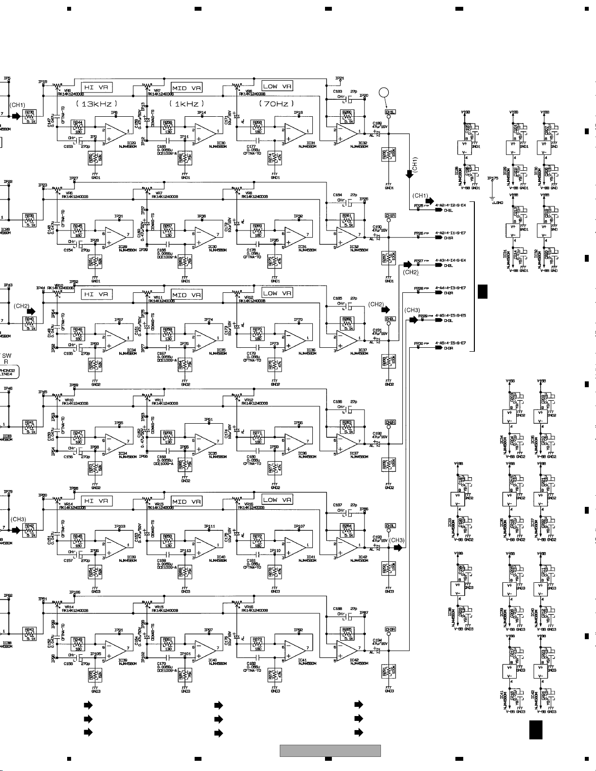
Channel equalizer(LINE/PHONO/MIC3)
.................................................
HI
.................................................
MID
.................................................
LOW
+12dB, –26dB (13kHz)
+12dB, –26dB (1kHz)
+12dB, –26dB (70Hz)
Microphone equalizer(MIC1, 2)
TREBLE
BASS
Effector
DELAY and ECHO
PAN, TRANS, FILTER and FLANGER
REVERB
PITCH
.........................................
.........................................
.............................
..............................................
..............................................
+12dB, –12dB (10kHz)
+12dB, –12dB (100Hz)
1 to 3500mSec
10 to 16000mSec
1 to 100%
0 to ±100%
Specifications and the design are subject to possible modifications
without notice, due to improvements.
D
E
F
56
DJM-3000
7
8
5
Page 6
1234
2. EXPLODED VIEWS AND PARTS LIST
NOTES:
A
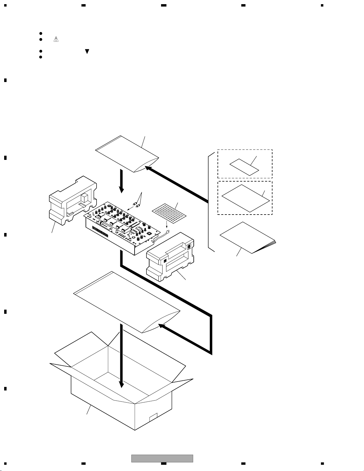
2.1 PACKING
B
C
Parts marked by "NSP" are generally unavailable because they are not in our Master Spare Parts List.
The mark found on some component parts indicates the importance of the safety factor of the part.
Therefore, when replacing, be sure to use parts of identical designation.
Screws adjacent to mark on product are used for disassembly.
For the applying amount of lubricants or glue, follow the instructions in this manual.
(In the case of no amount instructions, apply as you think it appropriate.)
4
9
5
To
PHONO (CH4)
6
8
RLBXCN
Type Only
KUCXCN
Type Only
2
7
D
3
E
1
F
6
1234
DJM-3000
Page 7

5678
PACKING parts List
Mark
No. Description Part No.
1 Packing Case See Contrast table(2)
2 Packing L 222302090
3 Packing R 222302100
4 Polyethylene Bag 222402210
(340 x 230 x 0.05)
5 Short Pin Plug AKM7008
Mark No. Description Part No.
6 Air Cap Sheet 222402260
7 Operating Instructions See Contrast table(2)
NSP 8 Warranty Card See Contrast table(2)
NSP 9 Caution Card 220V See Contrast table(2)
(2) CONTRAST TABLE
DJM-3000/KUCXCN, RLBXCN and WYXCN type are constructed the same except for the following :
A
Mark NO Symbol and Description
1 Packing Case 222302120 222302110 222302070
7 Operating Instructions (English/ French) DRB1314 Not used Not used
7 Operating Instructions
(English/ Spanish/ Chinese)
7 Operating Instructions (English/ French/
German/ Italian/ Dutch/ Spanish)
NSP 8 Warranty Card ARY7043 Not used Not used
NSP 9 Caution Card 220V Not used ARR7003 Not used
DJM-3000/
KUCXCN
Not used DRB1316 Not used
Not used Not used DRB1315
DJM-3000/
RLBXCN
DJM-3000/
WYXCN
B
C
D
56
DJM-3000
E
F
7
8
7
Page 8
1234
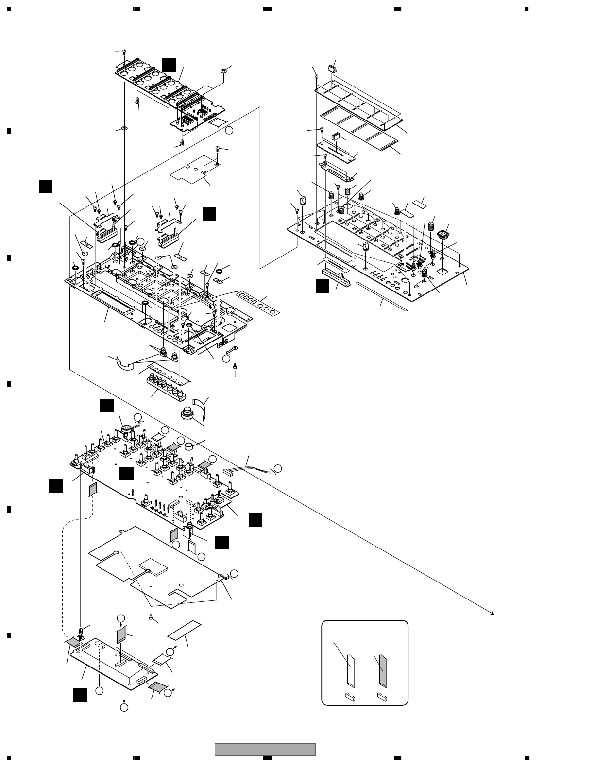
2.2 EXTERIOR(1/2) SECTION
30
A
32
69
31
38
29
28
33
31
42
40
28
36
B
C
K
2 to 5
44
33
37
33
28
33
38
K
28
31
K
32
42
38
31
40
1
33
6
38
29
29
39
F
34
29
38
D
44
28
39
41
66
55
66
65
60
66
61
D
66
50
13
56
55
47
46
58
59
57
27
60
62
64
54
67
52
63
49
49
51
53
48
14
25
35
H
10
7
D
16
K
C
B
C
11
E
E
E
E
45
20
18
43
D
J
68
33
24
15
26
P
17
23
H
12
J
J
NON-CONTACT
SIDE
CONTACT
SIDE
B
A
9
F
19
8
G
F
I
I
8
1234
21
F
22
DJM-3000
Page 9

5678
EXTERIOR(1/2) SECTION parts List
Mark No. Description Part No.
1 LED Assy 226902720
2 CHF1 Assy 226902860CH1
3 CHF2 Assy 226902860CH2
4 CHF3 Assy 226902860CH3
5 HF4 Assy 226902860CH4
6 MAF Assy 226902940
7 VR Assy 226903690
8 DSP Assy226902640
9 HP Assy 226902760
10 MIC Assy 226902780
11 CFCURV Assy 226903700
12 EFFECT Assy 226902740
13 CF Assy 226902960
14 Rubber Key CUE 224301330
15 Rubber Key TAP 224301340
16 Rubber Key LONG 224301360
17 PCB Sheet VR Assy 225300500
18 Plastic Rivet DEC1405
19 FFC Cable 28P 226404733
20 FFC Cable 21P 226404735
21 FFC Cable 35P 226404742
22 FFC Cable 31P 226404744
23 Connector Assy DKP3336
24 Blind Sheet TAP 225401850
25 Blind Sheet CUE 225401900
26 Rubber Holder 225401890
27 Brind Sheet 225402010
28 Nut M9 DBN1004
29 Screw AMZ26P040FMC
30 Screw VBA1039
31 Screw DBA1141
NSP 32 PCB Holder PNW1861
33 Screw BBZ30P060FMC
34 Shield Plate 225401840
35 Long Packing 225401730
Mark
No. Description Part No.
NSP 36 Panel Stay 224100480
37 Detect Arm DNK3750
38 Lever SW Packing DED1120
39 Slide SW Packing B DED1125
40 SW Packing A DED1145
41 Lock Sheet 225402000
42 Fader Bracket 225401690
43 Sheet 120 x 30 DED1160
44 Screw IBZ30P060FMC
NSP 45 PCB Holder PNW2174
46 Slider Panel 224402210
47 Slider Fitting Board DNF1518
48 Control Panel 224100460
49 Rotary VR Knob B DAA1136
50 Fader Knob DAC1846
51 Power Knob Guide DNK3207
52 Rotary Knob 224301310
53 Effect SW Knob 224301510
54 Sub Panel 224301280
55 Rotary SW Knob 224301350
56 Cross Fader Knob 224402230
57 VR Knob GR 224402260
58 VR Knob GY 224402270
59 VR Knob GG 224402280
60 VR Knob BK 224301300
61 Fader Packing B DED1100
62 Fader Packing 225300460
63 Display Panel A DAH2097
64 Display Panel B DAH2096
65 Screw AMZ30P040FMC
66 Screw CBZ30P080FZK
67 Select Knob 224301320
68 Nut NKX2FUC
69 Rubber Fwt 234404450
A
B
C
D
56
DJM-3000
E
F
7
8
9
Page 10
1234
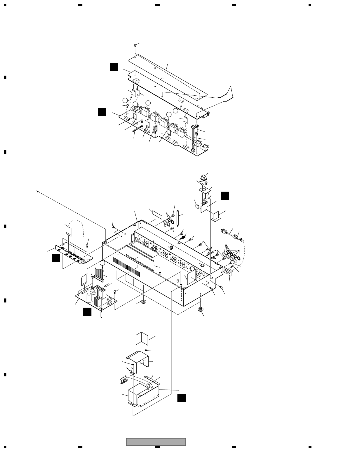
2.3 EXTERIOR(2/2) SECTION
A
3
B
51
25
2
B
C
D
B
4
L
5
A
48
25
24
23
I
25
52
10
25
17
40
39
36
16
35
49
B
C
H
A
50
34
26
38
54
29
29
53
18
30
32
24
29
30
O
1
19
8
33
31
44
29
24
12
24
47
59
41
56
46
31
55
58
44
29
22
29
14
60
57
G
M
45
37
15
43
42
28
6
E
43
9
N
F
10
1234
DJM-3000
Page 11
5678
EXTERIOR(2/2) SECTION parts List
Mark No. Description Part No.
1 PSW Assy 226902820
2 TERMA Assy 226902660
3 TERMB Assy 226902680
4 REG Assy 226902840
5 POWER Assy See Contrast table (2)
6 TRANS Assy See Contrast table (2)
7 • • • • •
8 Power Cord See Contrast table (2)
>
9 Power Transformer See Contrast table (2)
>
10 Fuse (1A) See Contrast table (2)
>
1 1 • • • • •
12 Power Cord Fitting Board DNF1640
1 3 • • • • •
14 Stand 225401830
15 Insulation Sheet L 225401990
NSP 16 Chassis 224301490
17 Nyron Rivet 3 x 4.5 RBM-003
18 Power Knob DAC1847
19 SW Insulaton Sheet 225402040
2 0 • • • • •
21 Sheet RHX1006
22 Screw PMB30P060FZK
23 Screw BBZ30P060FMC
24 Screw BBZ30P060FZK
25 Screw BMZ30P060FMC
26 Screw AMZ30P040FMC
27 Screw AMZ26P040FMC
28 Capacitor Cover 16 See Contrast table (2)
29 Screw BPZ30P080FZK
30 Washer DEC2484
Mark
No. Description Part No.
32 SW Plate 225401630
33 Cord Stopper See Contrast table (2)
NSP 34 PCB Support REC1248
35 Screw Guard 224402350
36 Clamper RNH-184
37 Wire Clamper RNH1005
38 Capacitor Cover 12.5 See Contrast table (2)
39 Binder ZCA-SKB90BK
40 PCB Sheet Rear 225300470
NSP 41 Wire Clip DEC1410
42 Trans. Shield 225300490
43 Nut M4 225401910
44 Nut NKX2FUC
45 Foot Assy REC-434
46 FFC Cable 12P 226404730
47 FFC Cable 19P 226404731
48 FFC Cable 24P 226404732
49 FFC Cable 21P 226404740
50 FFC Cable 15P 226404741
51 FFC Cable 20P 226404745
52 Connector Assy DKP3570
53 Connector Assy -DIG 226404650
54 Rubber Spacer 225401940
55 Net A 225401950
56 Net B 225401960
57 Insulation Sheet 225401970
NSP 58 Mini Clamp VEC1312
NSP 59 Serial Label See Contrast table (2)
60 Earth Ter minal AKE-03
A
B
C
31 Washer DBE1010
(2) CONTRAST TABLE
DJM-3000/KUCXCN, RLBXCN and WYXCN type are constructed the same except for the following :
Mark NO Symbol and Description
5 POWER Assy 226903790 226902700 226902700
6 TRANS Assy 226902800 226902801 226902800
>
>
>
>
NSP 16 Chassis 224301480 224301470 224301460
NSP 59 Serial Label
8 Power Cord ADG7024 VDG1061 VDG1061
9 Power Transformer 927001510 927001500 927001490
10 Fuse (1A) REK1075 Not used Not used
10 Fuse (T500MA) Not used AEK1051 AEK1051
33 Cord Stopper CM-22C CM-22B CM-22B
28 Capacitor Cover 16 Not used VEC1912 VEC1912
Capacitor Cover 12.5
38
DJM-3000/
KUCXCN
DRW1871
Not used
DJM-3000/
RLBXCN
RRW-168 RRW-168
225500120 225500120
DJM-3000/
WYXCN
D
E
56
DJM-3000
F
7
8
11
Page 12
1234
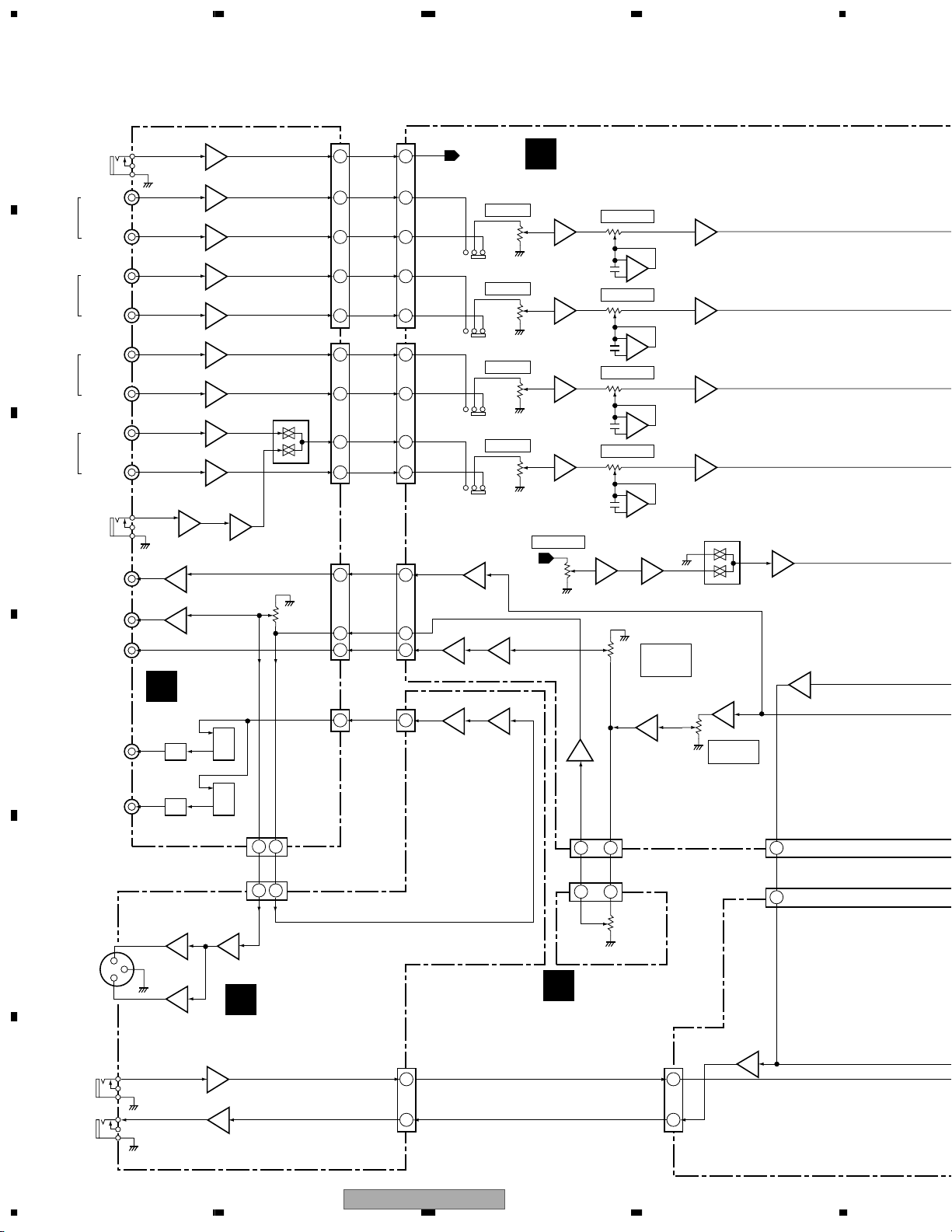
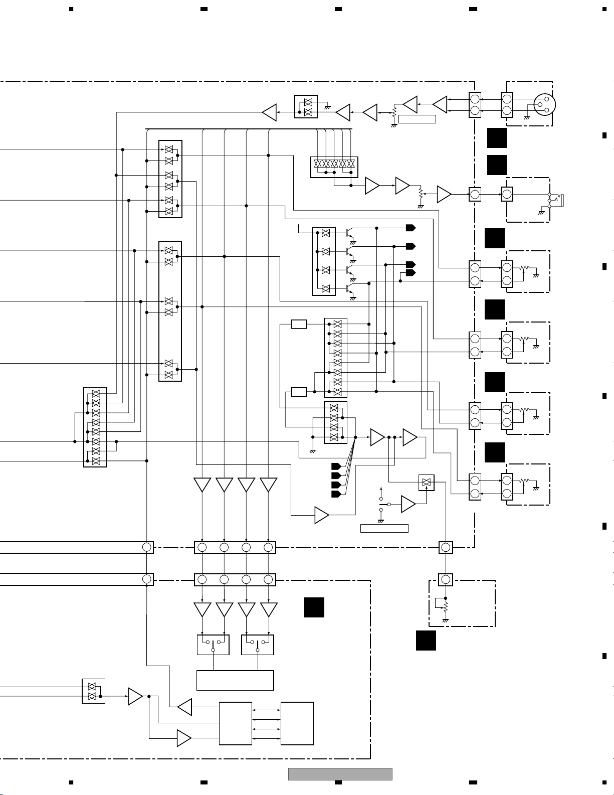
3. BLOCK DIAGRAM AND SCHEMATIC DIAGRAM
3.1 BLOCK DIAGRAM
A
IC600
3
MIC2
LINE1
CH1
(LCH)
PHONO1
/LINE2
LINE3
CH2
(LCH)
B
C
CH3
(LCH)
CH4
(LCH)
PHONO2
/LINE4
PHONO3
/LINE6
LINE5
PHONO4
LINE7
MIC3
REC OUT
MASTER
OUT1
BOOTH
MONITOR
IC502
1
1
IC17
5
IC7
A
D
DOUT1
DOUT2
4
4
1
IC1
5
7
IC2
5
7
IC4
5
7
IC5
5
7
IC12
5
7
IC14
5
7
IC16
5
7
IC15
5
7
IC18
5
7
3
3
TERMA
ASSY
1
37
IC500
1
37
IC501
CN4021 CN3021
MIC2
1
CH1-L1L
4
CH1-LPL
8
CH2-L1L
14
CH2-LPL
18
CN4022 CN3022
IC19
9
11
7
CN401 CN301
VR201
CN482
MASTER2L
DGL
CN480
14 15
CH3-LPL
5
CH3-L1L
1
15
11
9
5
1
1
CH4-
P4M3L
CH4-L7L
RECL
MTL2
BOTL
DOUT
10
1
4
8
14
18
5
1
15
11
9
5
1
1
CN582
MIC2
123
123
123
12
3
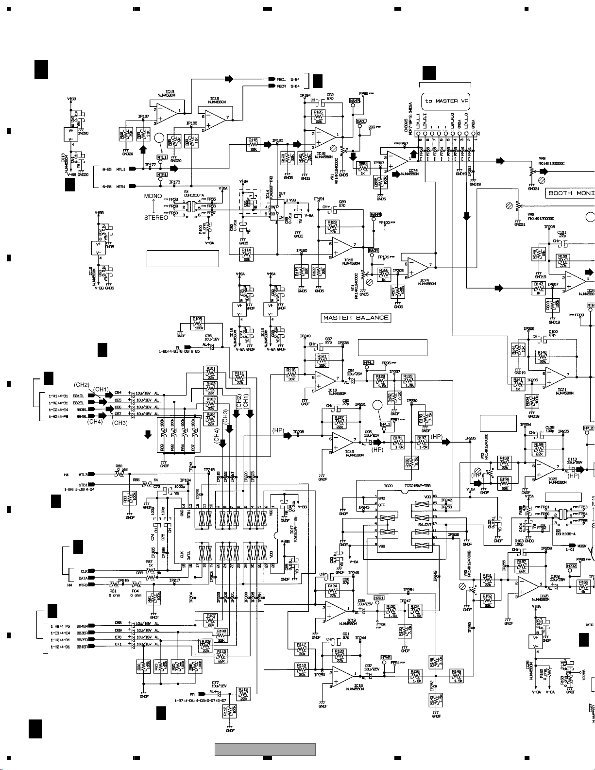
IC13
3
1
IC24
55
7
7
IC9
6
7
1
TRIM VR
VR5
S5
TRIM VR
VR9
S6
TRIM VR
VR13
S7
TRIM VR
VR21
S8
MIC2
IC23
IC9
2
VR ASSY
C
IC28
5
IC33
5
IC38
5
IC49
5
MIC LEVEL
VR26
7
7
7
7
IC704
3
1
IC21
3
LEVEL_L_O
2
EQ VR ×3
VR6
2
3
EQ VR ×3
VR10
2
3
EQ VR ×3
VR14
2
3
EQ VR ×3
VR22
2
3
IC50-IC52
IC57
13 1
VR2
IC74
1
LEVEL_L_I
CN3005
9
1
IC29-IC31
1
IC34-IC36
1
IC39-IC41
1
BOOTH
MONITOR
LEVEL
3
2
2
2
2
4
11
IC32
IC37
IC42
IC53
IC700
IC15
1
VR1
MASTER
BALANCE
1
1
1
1
CN305
IC60
3
10
3
1
IC67
6
7
19
CN205
IC101
1
SGLI
19
2
14 15
E
MASTER
OUT2
RETURN
F
SEND
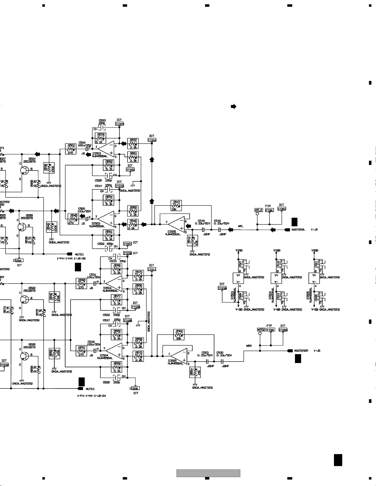
IC503
7L+
IC503
1
L–
5
2
2
IC101
7
IC102
IC505
7
B
1
6
12
CN580
5
TERMB ASSY
(1/2)
F
CN583
11
15
DJM-3000
9
2
CN335
VR32
MAF ASSY
RETURN_LRETURN_L
SEND_LSEND_L
11
15
CN261
1234
Page 13
5678
A
IC55
6
7
3
1
IC12
CN350
J3072
5
6
IC27
J3082
CN3001
CN3002
CN3003
3
1
1
CN3004
3
4 4
1
8
4
8
4
8
4
8
4
3
3
1
CN304
IC700
IC17
5V
IC4
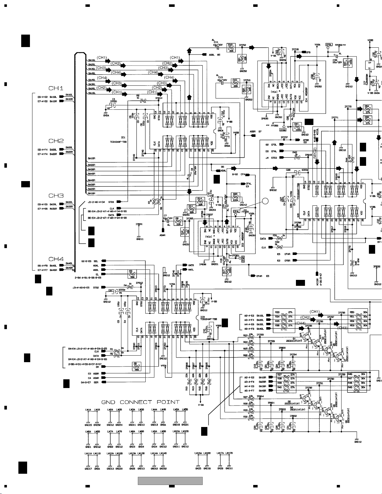
VCA
IC2
VCA
23 26
83
83
2
IC703
IC56
3
1
1
EL
BB3EL
BB2EL
BB1EL
BB4EL
7
62
10
9
2
3
5
6
1GL
2GL
3GL
4GL
IC10
IC3
345
6
IC18 IC25
676
Q1
27
Q3
25
Q5
24
Q7
IC1
3
4
5
11
10
8
7
4
2
7
IC5
MIC
MIX
1
TALK OVER SW
IC9
IC59
1
IC43
MICL
IC66
2
5
9
12
3
4
6
7
8
10
11
EL
2
3
8
9
5
6
IC44
2
3
5
6
8
9
9
BB4EL
BB3EL
BB2EL
4
10
7
4
7
10
3
3
IC7
IC73
IC8
1
1
19
17
BB1EL
3
IC6
1
21
24
2
1
S9
IC54
7
MIC1 LEVEL
7
4GL
3GL
2GL
1GL
IC11
2
4
7
5
IC71
J3071
HOT
3
COLD
MIC ASSY
H
HP ASSY
P
J3081
HSLD
1
G
CHF1 ASSY
CN331
1EL
8
1GL
4
G
CHF2 ASSY
CN331
2EL
8
2GL
4
G
CHF3 ASSY
CN331
3EL
8
3GL
4
G
CHF4 ASSY
CN331
4EL
8
4GL
4
MIC 1
PHONES
B
VR17
C
VR17
VR17
D
VR17
IC115
2
356
IC117
56
SGLO
9
7
4EL
19
5
5 3 12 13
IC110
IC124
SGLO
7
6
AINL–
21
AINL+
IC117
3EL
17
6
2
IC106
IC105
1
IC108
Microcomputer
IC122
AD/DA
21
2EL
6
IC104
7
24
144
2524
SCLK
SDT0
SDTI
LRCK
1EL
1
CN204
2
IC104
IC110
I
DSP ASSY
IC119
DSP
DJM-3000
TALK
_ML
1
CN510
VR101
TERMB ASSY
B
(2/2)
E
F
7
8
13
Page 14
6
1234
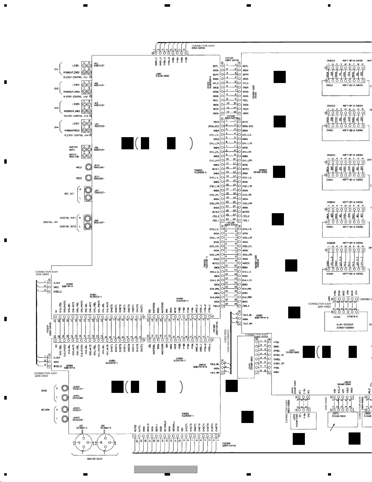
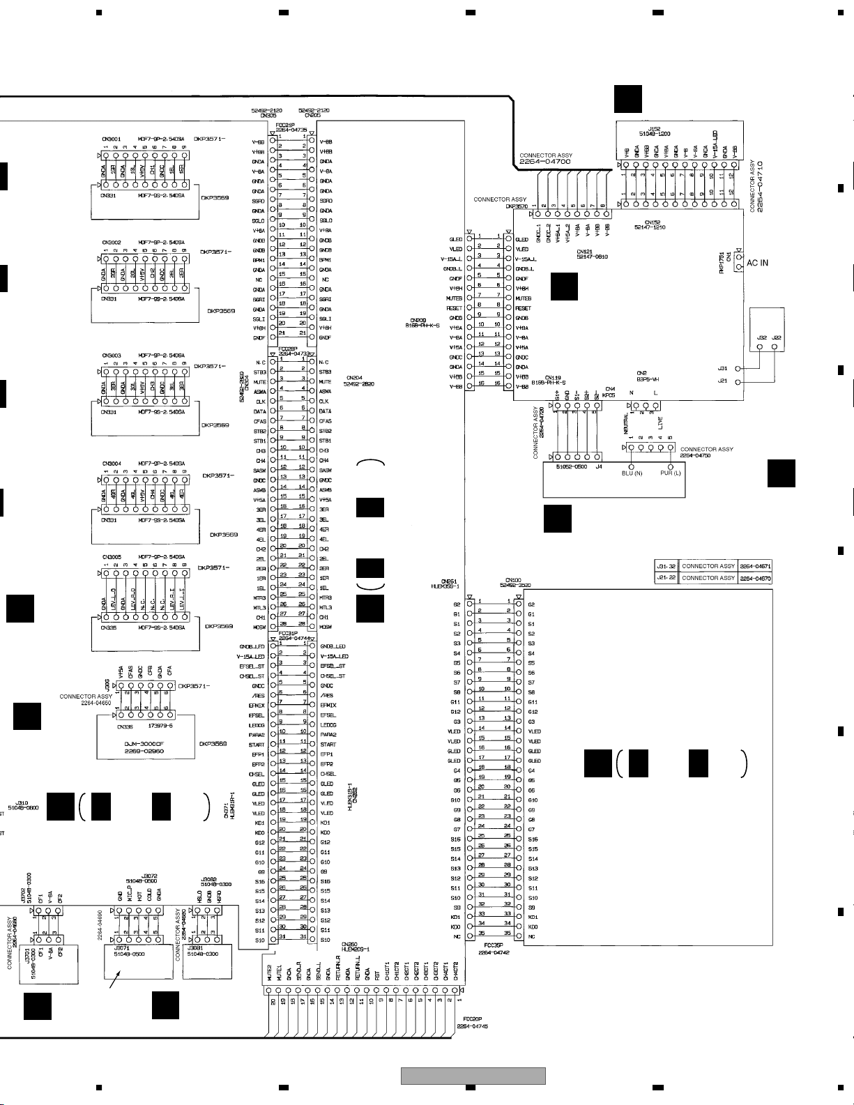
3.2 OVERALL WIRING CONNECTION DIAGRAM
A
Note : When ordering service parts, be sure to refer to "EXPLODED VIEWS and PARTS LIST" or "PCB PARTS LIST".
G
CHF1 ASSY
(226902860CH1)
B
A
TERMA ASSY
(226902660)
A 1/3- A 3/3
G
CHF2 ASSY
(226902860CH2)
G
CHF3 ASSY
(226902860CH3)
C
G
CHF4 ASSY
(226902860CH4)
F
D
MAF ASSY
(226902940)
D
CF ASSY
(226902960)
E
B
TERMB ASSY
(226902680)
B 1/4- B 4/4
J
EFFECT ASSY
(226902740)
C
VR ASSY
(226903690)
C 1/8- C 8/8
E
CFCURV ASSY
F
14
1234
DJM-3000
(226903700)
MIC ASSY
H
(226902780)
P
HP
(22
Page 15
5678
LIST".
1 ASSY
902860CH1)
F2 ASSY
6902860CH2)
3 ASSY
902860CH3)
REG ASSY
L
(226902840)
M
POWER ASSY
(KUCXCN : 226903790)
(WYXCN, RLBXCN : 226902700)
A
B
PSW ASSY
(226902820)
C
O
4 ASSY
902860CH4)
F
MAF ASSY
(226902940)
D
CF ASSY
(226902960)
C
VR ASSY
(226903690)
C 1/8- C 8/8
I 1/3- I 3/3
I
DSP ASSY
(226902640)
TRANS ASSY
N
(KUCXCN, WYXCN : 226902800)
(RLBXCN : 226902801)
K
LED ASSY
(226902720)
K 1/2, K 2/2
D
E
MIC ASSY
H
(226902780)
HP ASSY
(226902760)
P
56
DJM-3000
F
7
8
15
Page 16
1234
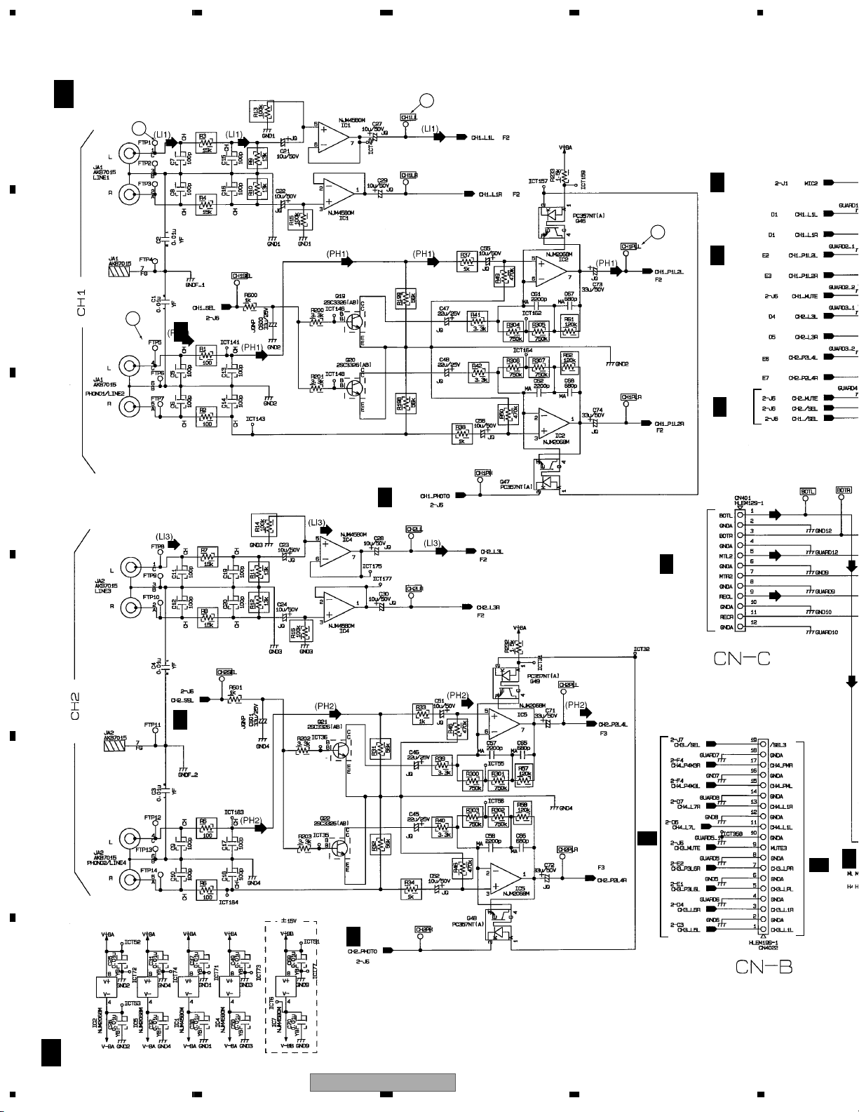
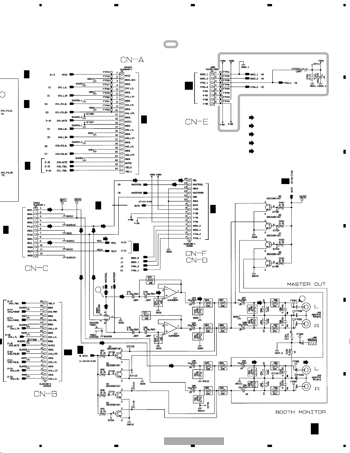
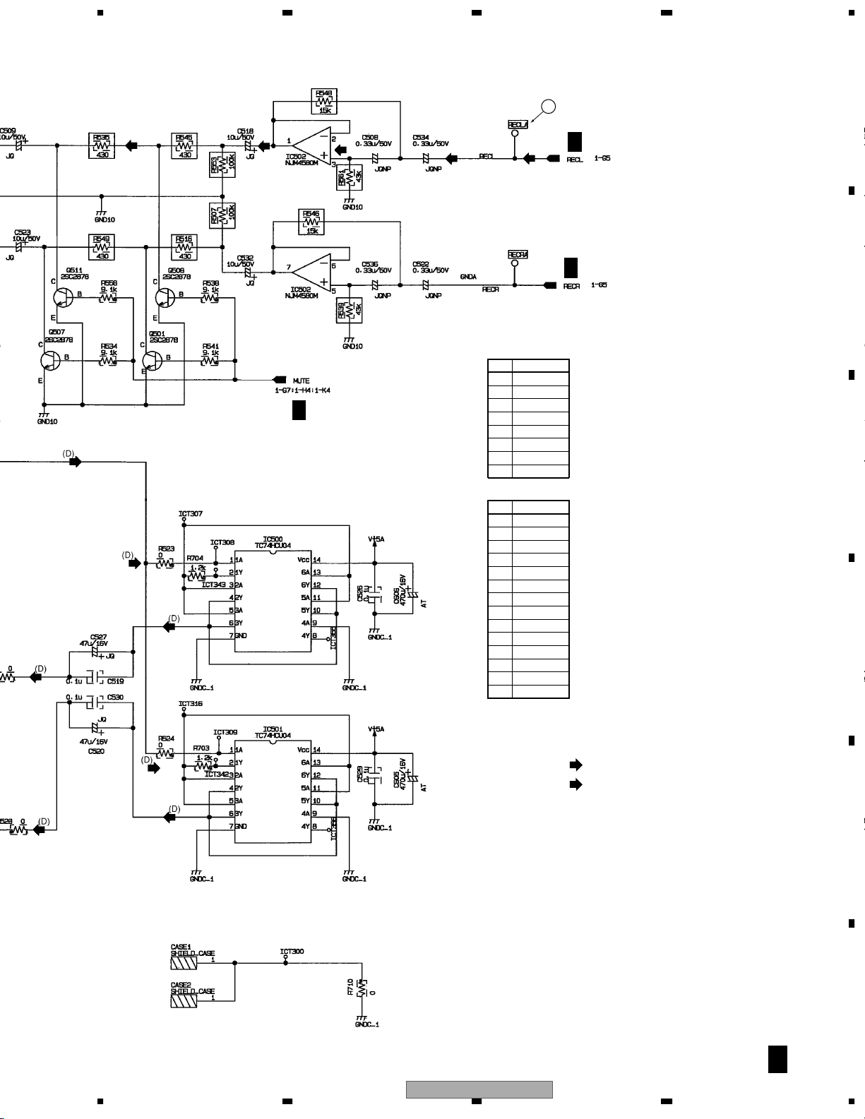
3.3 TERMA(1/3) ASSY
A
A 1/3
TERMA ASSY
2
(226902660)
1
A 2/3
6
A 2/3
B
5
A 2/3
A 2/3
C
A 2/3
C 5/8
CN301
D
A 2/3
E
A 2/3
CN3022
A
C 5/8
A 2/3
F
A 1/3
16
1234
DJM-3000
Page 17
A 2/3
5678
: The power supply is shown with the marked box.
A
A 2/3
M
6
CN121
A 2/3
B
C 3/8
CN3021
: AUDIO SIGNAL ROUTE
(LI1)
: AUDIO SIGNAL ROUTE (LINE1)
(LI3)
: AUDIO SIGNAL ROUTE (LINE3)
(PH1)
: AUDIO SIGNAL ROUTE (PHONO1)
(PH2)
: AUDIO SIGNAL ROUTE (PHONO2)
A 2/3
A 3/3
C
C 5/8
CN301
CN3022
A 3/3
C 5/8
A 3/3
3
B 1/4
CN580
A 3/3
D
4
E
56
DJM-3000
F
A 1/3
7
8
17
Page 18
1234
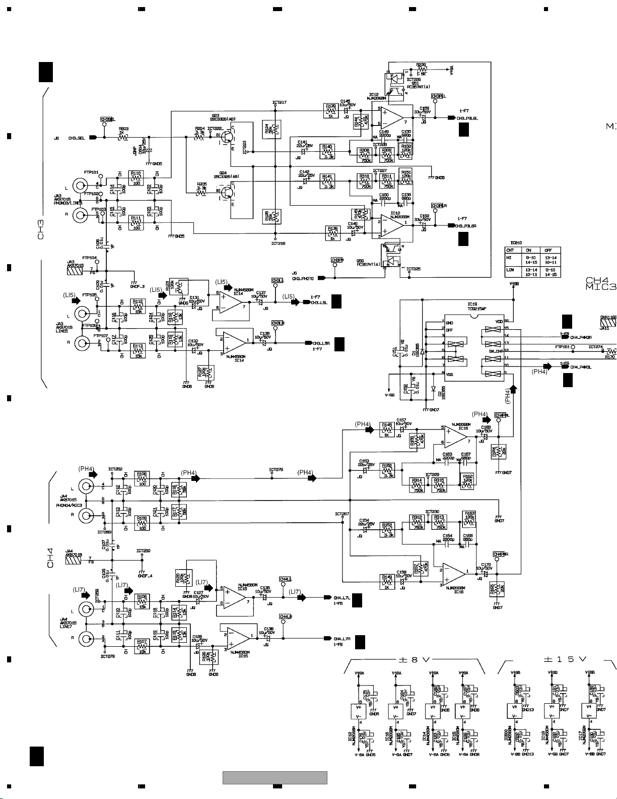
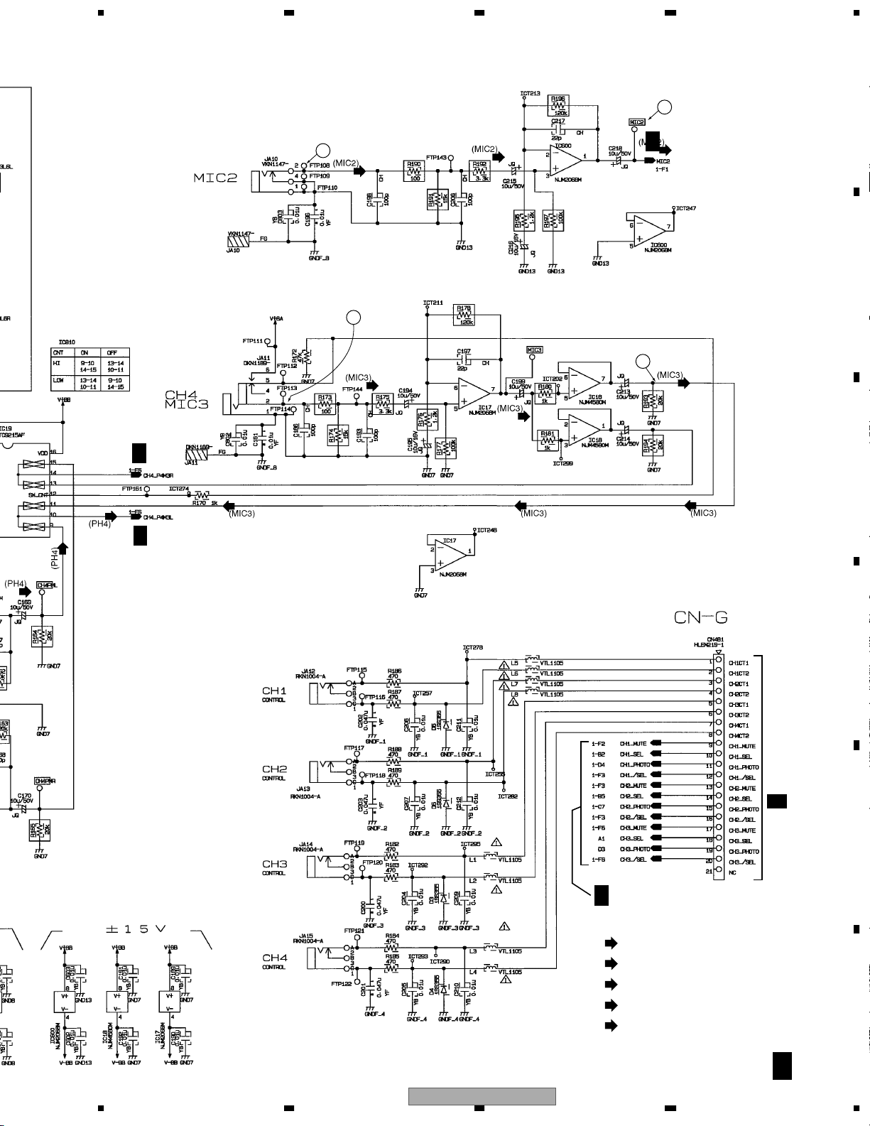
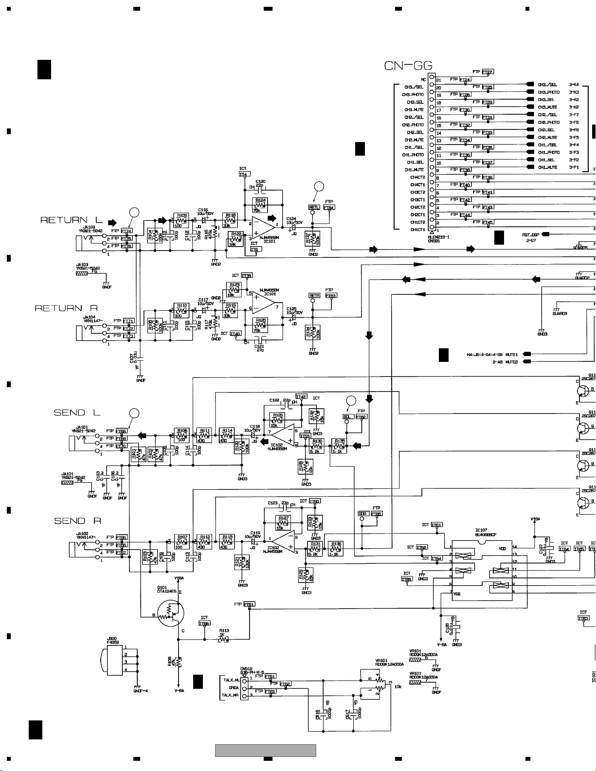
3.4 TERMA(2/3) ASSY
A
A 2/3
TERMA ASSY
(226902660)
A 1/3
B
A 1/3
A 1/3
A 1/3
C
A 1/3
A 1/3
D
E
A 1/3
A 1/3
F
A 2/3
18
1234
DJM-3000
Page 19
5678
1/3
1/3
A 1/3
8
7
9
A 1/3
10
A
B
C
A 1/3
A 1/3
(LI5)
: AUDIO SIGNAL ROUTE (LINE5)
(LI7)
: AUDIO SIGNAL ROUTE (LINE7)
(PH4)
: AUDIO SIGNAL ROUTE (PHONO4)
(MIC2)
: AUDIO SIGNAL ROUTE (MIC2)
(MIC3)
: AUDIO SIGNAL ROUTE (MIC3)
D
CN581
B 1/4
E
F
56
DJM-3000
A 2/3
7
8
19
Page 20

1234
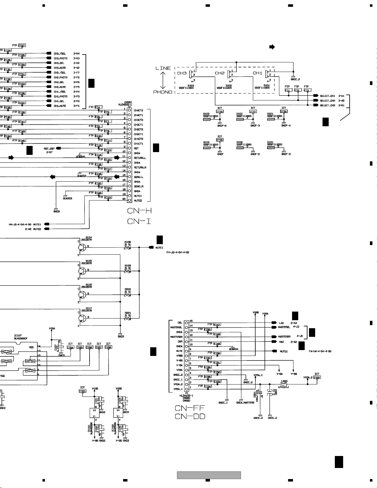
3.5 TERMA(3/3) ASSY
A
B
C
A 3/3
TERMA ASSY
(226902660)
12
13
B 2/4
CN582
PULSE TRANS. CASE
>
D
1514
>
>
E
>
Mounted Parts Side
F
A 3/3
20
PULSE TRANS. CASE
Foil Side
DJM-3000
1234
Page 21
5678
A 1/3
11
IC502
No. Voltage (V)
10
20
30
4 -15.29
50
60
70
8 14.96
IC500
No. Voltage (V)
1 2.38
2 2.57
3 2.55
4 2.51
5 2.55
6 2.51
70
8 5.01
90
10 2.51
11 2.55
12 2.51
13 2.55
14 5.01
A 1/3
A 1/3
A
B
C
D
Mounted Parts Side
Foil Side
56
DJM-3000
: AUDIO SIGNAL ROUTE
(D)
: AUDIO SIGNAL ROUTE (DOUT)
7
E
F
A 3/3
21
8
Page 22
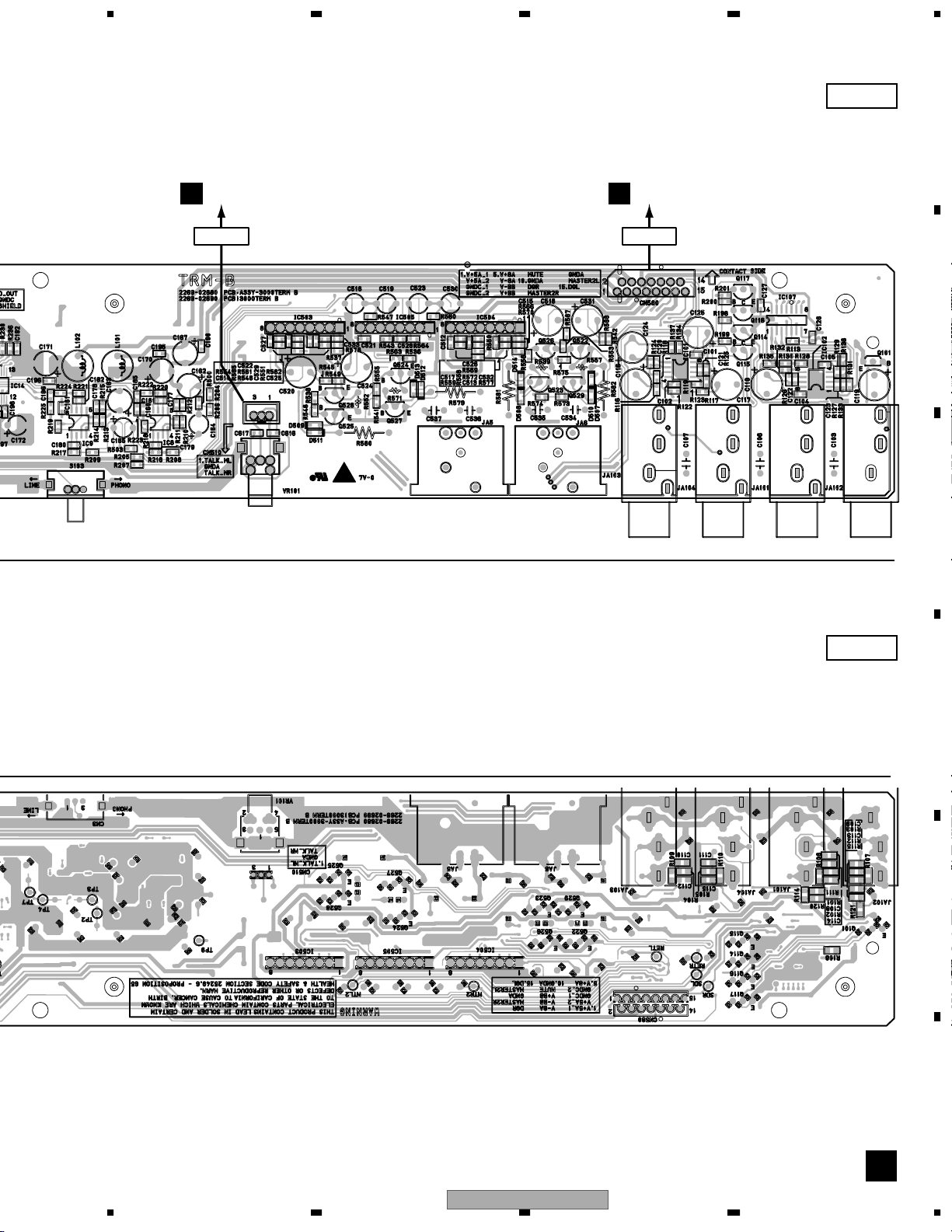
1234
B
3.6 TERMB(1/4) ASSY
A
B 1/4
TERMB ASSY
(226902680)
A 2/3
CN481
B
1
2
B 2/4
C
B 2/4
4
3
D
E
F
B 1/4
22
C 1/8
CN350
DJM-3000
1234
Page 23
5678
B 2/4
B 3/4
I 1/3
CN260
: AUDIO SIGNAL ROUTE
B 3/4
A
B
C
/4
B 4/4
A 1/3
CN480
D
B 2/4
B 4/4
B 2/4
E
56
DJM-3000
F
B 1/4
7
8
23
Page 24
1234
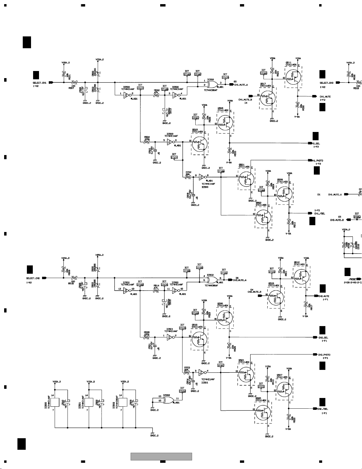
3.7 TERMB(2/4) ASSY
A
B 2/4
TERMB ASSY
(226902680)
B 1/4
B
B 1/4
C
D
E
F
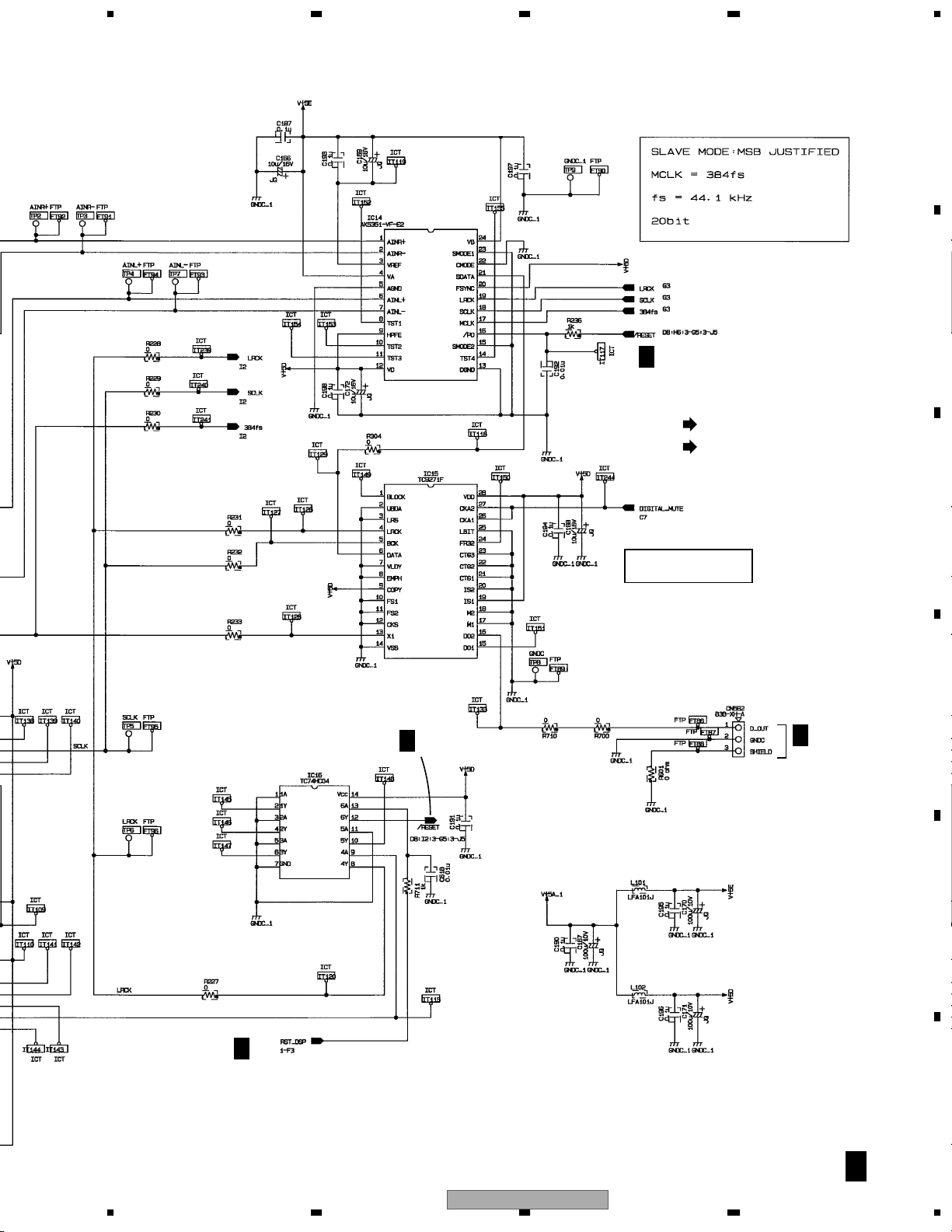
B 2/4
24
B 1/4
B 3/4
MUTE CIRCUIT OF
DIGITAL SECTION
DJM-3000
1234
Page 25
5678
A
B
B 3/4
: AUDIO SIGNAL ROUTE
(D)
: AUDIO SIGNAL ROUTE (DOUT)
B 3/4
C
2 ch MODE
GENERAL FORMAT
D
A 3/3
CN482
E
B 1/4
DJM-3000
56
F
B 2/4
7
8
25
Page 26
1234
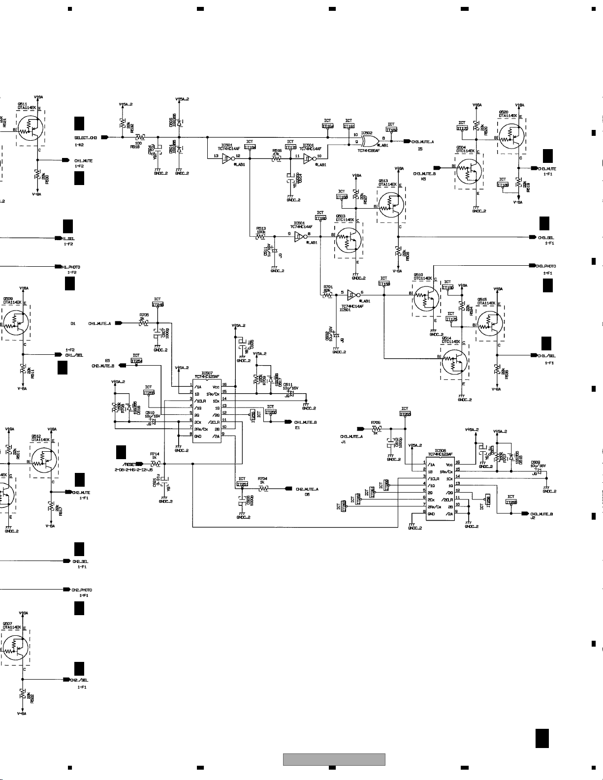
3.8 TERMB(3/4) ASSY
A
B 3/4
TERMB ASSY
(226902680)
B 1/4
B 1/4
B 1/4
B
B 1/4
B 1/4
C
B 1/4
D
B 1/4
B 2/4
B 1/4
B 1/4
E
B 1/4
F
B 3/4
26
B 1/4
DJM-3000
1234
Page 27
B 1/4
B 1/4
5678
A
B 1/4
B
B 1/4
B 1/4
B 1/4
B 1/4
B 2/4
B 1/4
B 1/4
C
B 1/4
D
B 1/4
B 1/4
B 1/4
56
DJM-3000
E
F
B 3/4
7
8
27
Page 28
1234
4
/
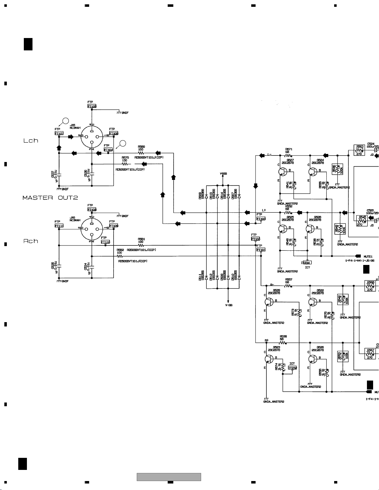
3.9 TERMB(4/4) ASSY
A
B 4/4
TERMB ASSY
(226902680)
B
C
5
6
B 1/
D
E
B 1
F
B 4/4
28
1234
DJM-3000
Page 29
5678
A
: AUDIO SIGNAL ROUTE
B
B 1/4
B 1/4
B 1/4
C
D
E
B 1/4
DJM-3000
56
F
B 4/4
7
8
29
Page 30
1234
/
3.10 VR(1/8) ASSY
A
B
C
C 1/8
C 4/8
VR ASSY
(226903690)
CROSS FADER ASSIGN
C 6/8
C
4/8,5/8
C 4/8
C 4/8
1
C 2/8,4/8
C 2/8,4/8,6/8
C 6
C 2/8,4/8,6/8
D
C
4/8,5/8
C 4/8,6/8
C 4/8
C 2/8,4/8,6/8
E
C 6/8
F
C 1/8
30
C 4/8
DJM-3000
1234
Page 31

5678
C
4/8,5/8
C 4/8
C 4/8
C 4/8
C 2/8
C
2/8
C 2/8,4/8
C 4/8,6/8
2
C 2/8
C 4/8
C 6/8
C 4/8
C 2/8
C 4/8
C 2/8
C 6/8
CN204
I 1/3
A
B
C
C
4/8,5/8
C 6/8
C 4/8
C 4/8
C 5/8
C 6/8
: AUDIO SIGNAL ROUTE
(MIC1)
: AUDIO SIGNAL ROUTE (MIC1)
(MIC2)
: AUDIO SIGNAL ROUTE (MIC2)
(CH1)
: AUDIO SIGNAL ROUTE (CH1)
(CH2)
: AUDIO SIGNAL ROUTE (CH2)
(CH3)
: AUDIO SIGNAL ROUTE (CH3)
(CH4)
: AUDIO SIGNAL ROUTE (CH4)
B 1/4
CN510
D
E
F
56
DJM-3000
C 1/8
7
8
31
Page 32
1234
1
3.11 VR(2/8) and HP ASSY
A
B
C
C 2/8
VR ASSY
(226903690)
C 6/8
C 1/8,4/8,6/8
3
MASTER
STEREO/MONO SW
C 5/8
HEADPHONE
SPLIT MONITOR SW
F
CN335
4
C 1/8,4/8
5
MONITOR
BALANCE
D
C 1/8,4/8
SPLIT SW
C 1/8,4/8,6/8
E
C 1/8,4/8
C
F
C 2/8
32
C 1/8,4/8,6/8
DJM-3000
1234
Page 33

5678
335
A
C 5/8
C 5/8
4
B
C 5/8
C 5/8
C
MONITOR
BALANCE
SPLIT SW
C 1/8
MONITOR LEVEL
C 1/8
C 1/8
: AUDIO SIGNAL ROUTE
(CH1)
: AUDIO SIGNAL ROUTE (CH1)
(CH2)
: AUDIO SIGNAL ROUTE (CH2)
(CH3)
: AUDIO SIGNAL ROUTE (CH3)
(CH4)
: AUDIO SIGNAL ROUTE (CH4)
(HP)
: AUDIO SIGNAL ROUTE (PHONES)
DJM-3000
56
HSL0
GND
HSR0
J3081
51048-0300
FTP910
1
2
3
FTP
(HP)
7
FTP
FTP912
FTP
FTP911
R502
R503
R504
C 5/8
D
E
P
HP ASSY
(226902760)
FTP
FTP914
FTP
C370
FTP913
FTP
FTP916
FTP
FTP915
(HP)
GNDB
C 2/8
12L
3
JA302
YKB21-5264
R
8
PHONES
F
P
33
1
0
(HP)
0
0
YF
0.01U
G_GND
Page 34

1234
A
A
A
3.12 VR(3/8) ASSY
A
B
C 3/8
VR ASSY
(226903690)
C 5/8
6
CN4021
C
A 1/3
D
E
F
C 3/8
34
C 5/8
(LI1)
: AUDIO SIGN
(LI2)
: AUDIO SIGN
(LI5)
DJM-3000
1234
: AUDIO SIGN
Page 35
5678
A
7
B
C 4/8,6/8
C
D
E
(LI1)
: AUDIO SIGNAL ROUTE (LINE1)
(LI2)
: AUDIO SIGNAL ROUTE (LINE2)
(LI5)
: AUDIO SIGNAL ROUTE (LINE5)
56
(PH1)
: AUDIO SIGNAL ROUTE (PHONO1)
(PH2)
: AUDIO SIGNAL ROUTE (PHONO2)
(PH3)
: AUDIO SIGNAL ROUTE (PHONO3)
(CH1)
(CH2)
(CH3)
DJM-3000
: AUDIO SIGNAL ROUTE (CH1)
: AUDIO SIGNAL ROUTE (CH2)
: AUDIO SIGNAL ROUTE (CH3)
7
F
C 3/8
35
8
Page 36

1234
H
3.13 VR(4/8) ASSY
A
C 4/8
VR ASSY
(226903690)
C 1/8,2/8
C 1/8,2/8
C 1/8,2/8,6/8
C 1/8,2/8,6/8
C 1/8
B
C 3/8,6/8
C 5/8,6/8
C 5/8,6/8
C 1/8
C 1/8,2/8,6/8
C 1/8
C
C 1/8
C 3/8,6/8
C 1/8,2/8,6/8
C 1/8,2/8
C 1/8,2/8
D
C 3/8,6/8
C 5/8,6/8
E
C 1/8,5/8
C 1/8
C 1/8,5/8
C 1/8
C 1/8
C 1/8
C 1/8
C 1/8
G
F
C 4/8
36
C 5/8,6/8
C 1/8,6/8
C 1/8,2/8,6/8
DJM-3000
1234
C
C
Page 37

5678
1/8
C 1/8,2/8,6/8
C 1/8
C 1/8,2/8
C 1/8
G
CH1
CN331
(MIC1)
(MIC2)
C 3/8,6/8
CN331
G
CH2
: AUDIO SIGNAL ROUTE (MIC1)
: AUDIO SIGNAL ROUTE (MIC2)
(CH1)
: AUDIO SIGNAL ROUTE (CH1)
(CH2)
: AUDIO SIGNAL ROUTE (CH2)
(CH3)
: AUDIO SIGNAL ROUTE (CH3)
(CH4)
: AUDIO SIGNAL ROUTE (CH4)
A
B
C
C 1/8
C 1/8
C 1/8
G
CH3
CN331
G
CH4
C 1/8
CN331
D
E
C 5/8,6/8
F
56
DJM-3000
C 4/8
7
8
37
Page 38

1234
L
C
C
H
3.14 VR(5/8) ASSY
A
C 5/8
VR ASSY
(226903690)
(
(P
(MI
(MI
(C
C 3/8
B
CN4022
A 1/3
C 3/8
C
CN401
A 1/3
C 2/8
8
H
J3071
D
E
C 3/8
F
C 5/8
38
C 1/8
DJM-3000
1234
Page 39

5678
: AUDIO SIGNAL ROUTE
(LI7)
: AUDIO SIGNAL ROUTE (LINE7)
(PH4)
: AUDIO SIGNAL ROUTE (PHONO4)
(MIC1)
: AUDIO SIGNAL ROUTE (MIC1)
(MIC2)
: AUDIO SIGNAL ROUTE (MIC2)
(CH4)
: AUDIO SIGNAL ROUTE (CH4)
A
B
C 4/8,6/8
C
3/8
9
C 4/8,6/8C 1/8,4/8
D
E
56
DJM-3000
F
C 5/8
7
8
39
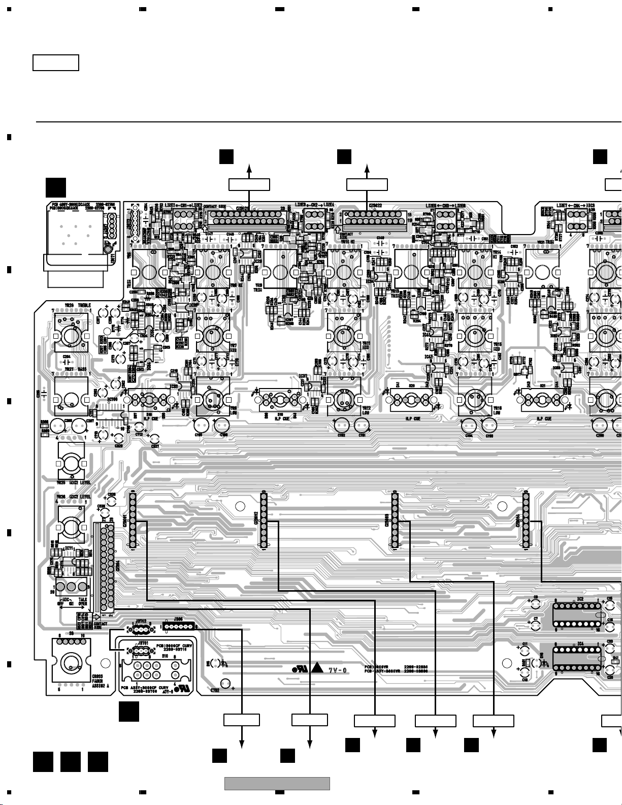
Page 40

1234
3.15 VR(6/8), CF and CFCURV ASSYS ASSY
A
D
CF ASSY
(226902960)
B
C 1/8
C
C 6/8
C 4/8,5/8
C 3/8,4/8
D
10
C 4/8,5/8
C 1/8
C 1/8,2/8,4/8
C 2/8
C 1/8,4/8
C 1/8,2/8,4/8
E
CN205
F
C 6/8
40
I 3/3
C 4/8
C 1/8,2/8,4/8
C 2/8
C 1/8,2/8,4/8
C 1/8
C 4/8,5/8
C 3/8,4/8
C 4/8,5/8
D
DJM-3000
1234
C 1/8
Page 41

5678
A
C 6/8
C 1/8
CFCURV ASSY
E
(226903700)
C 6/8
: AUDIO SIGNAL ROUTE
(MIC1)
: AUDIO SIGNAL ROUTE (MIC1)
(CH1)
: AUDIO SIGNAL ROUTE (CH1)
(CH2)
: AUDIO SIGNAL ROUTE (CH2)
(CH3)
: AUDIO SIGNAL ROUTE (CH3)
(CH4)
: AUDIO SIGNAL ROUTE (CH4)
VR ASSY
(226903690)
B
C
,5/8
8
/8
C 1/8,4/8
1/8,2/8,4/8
C 2/8
1/8
/8
D
E
8,5/8
C 1/8
56
DJM-3000
F
C 6/8
7
E
41
8
Page 42

1234
3.16 VR(7/8) ASSY
A
C 7/8
B
VR ASSY
(226903690)
C
D
CN262
I 1/3
E
C 8/8
F
C 7/8
42
J3101
J
1234
DJM-3000
Page 43

5678
A
B
C
D
E
56
DJM-3000
F
C 7/8
7
8
43
Page 44

1234
3.17 VR(8/8) ASSY
A
C 8/8
VR ASSY
(226903690)
B
C 7/8
C
C 7/8
C 7/8
D
C 7/8
E
C 7/8
C 7/8
F
C 8/8
44
1234
DJM-3000
Page 45

5678
3.18 MAF, CHF1-4 and MIC ASSYS
MAF ASSY
F
(226902940)
C 4/8
C 2/8
CN305
C 4/8
C 4/8
C 4/8
CH FADER VR
CN3001 (CH1)
CN3002 (CH2)
CN3003 (CH3)
CN3004 (CH4)
CHF1 ASSY (226902860CH1)
G
CHF2 ASSY (226902860CH2)
CHF3 ASSY (226902860CH3)
CHF4 ASSY (226902860CH4)
A
B
MIC ASSY (226902780)
H
C
CH FADER VR
D
C 5/8
J3072
E
56
DJM-3000
F
F G H
7
8
45
Page 46

1234
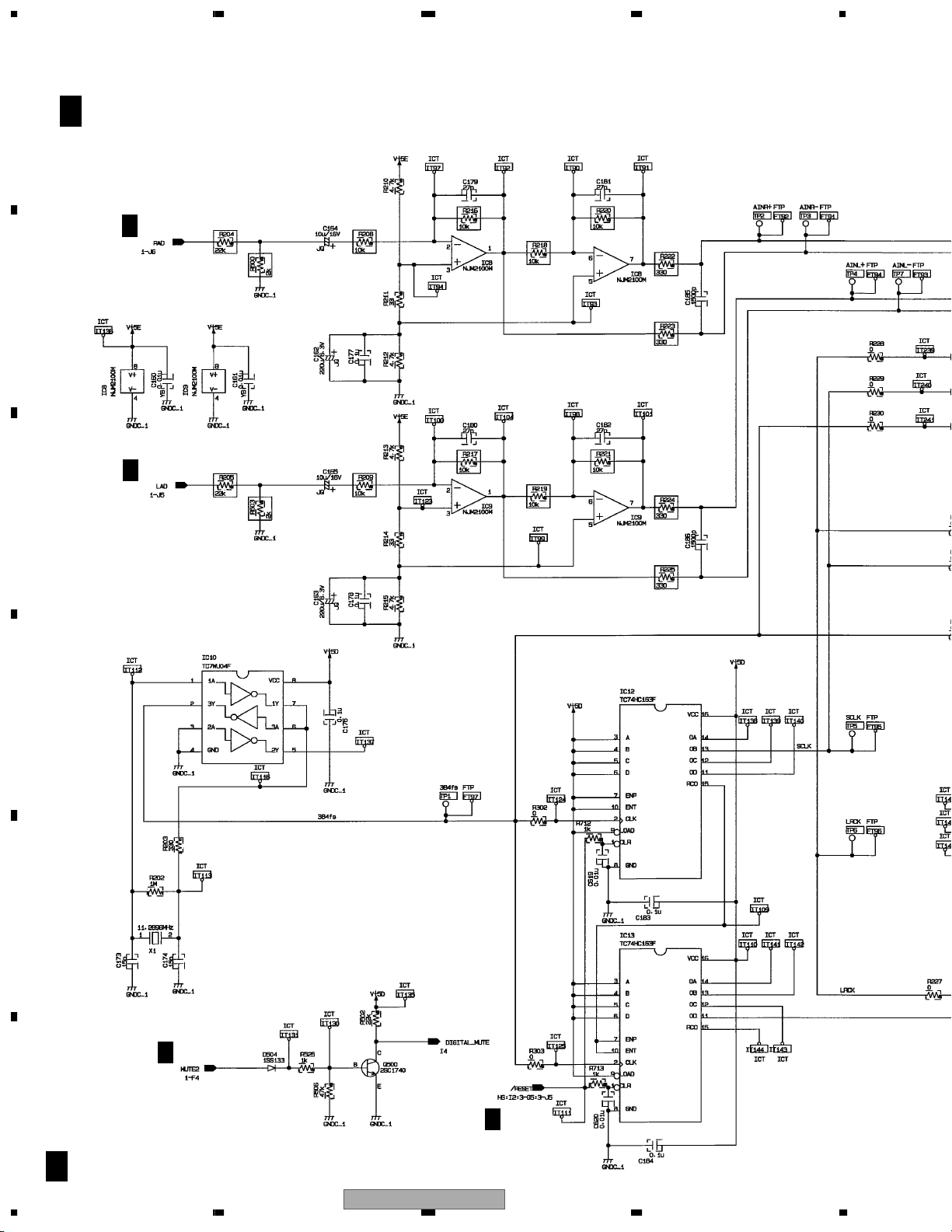
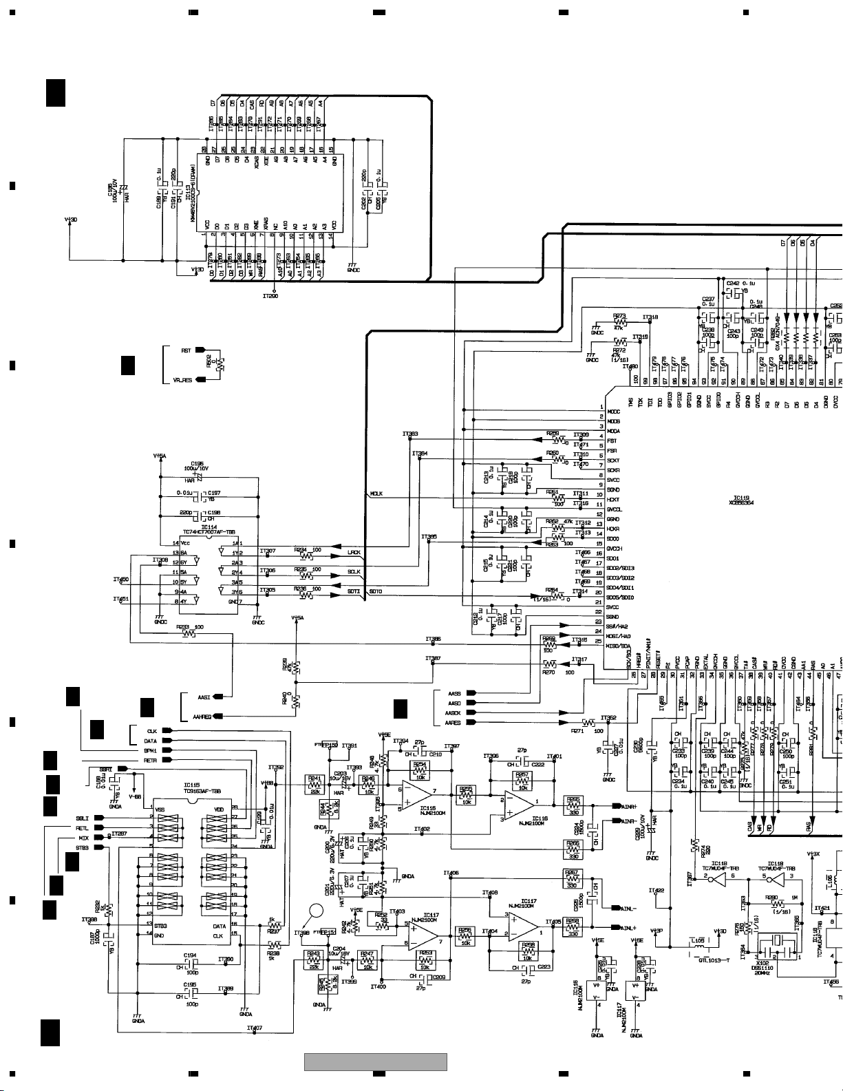
3.19 DSP(1/3) ASSY
A
I 1/3
DSP ASSY (226902640)
I 2/3
I 3/3
1
I 2/3
B
C
I 2/3,3/3
D
I 2/3
E
I 2/3
F
I 1/3
46
CN371
C 7/8
1234
DJM-3000
Page 47

5678
I 2/3
I 3/3
I 2/3
B 1/4
I 2/3
CN583
A
B
K 1/2
CN100
C
C 7/8
I 2/3
D
C 1/8
CN304
E
F
CN371
56
DJM-3000
I 1/3
7
8
47
Page 48
1234
3.20 DSP(2/3) ASSY
A
I 2/3
DSP ASSY
(226902640)
B
I 1/3
C
D
I 3/3
I 1/3
I 1/3
I 1/3
I 2/3
I 3/3
I 3/3
E
I 1/3
I 3/3
I 2/3
F
2
I 2/3
48
1234
DJM-3000
Page 49

5678
A
1.345V
5V
4.39V
1.25V
I 1/3
3
I 3/3
B
I 1/3
C
I 1/3
D
E
F
56
DJM-3000
I 2/3
7
8
49
Page 50
1234
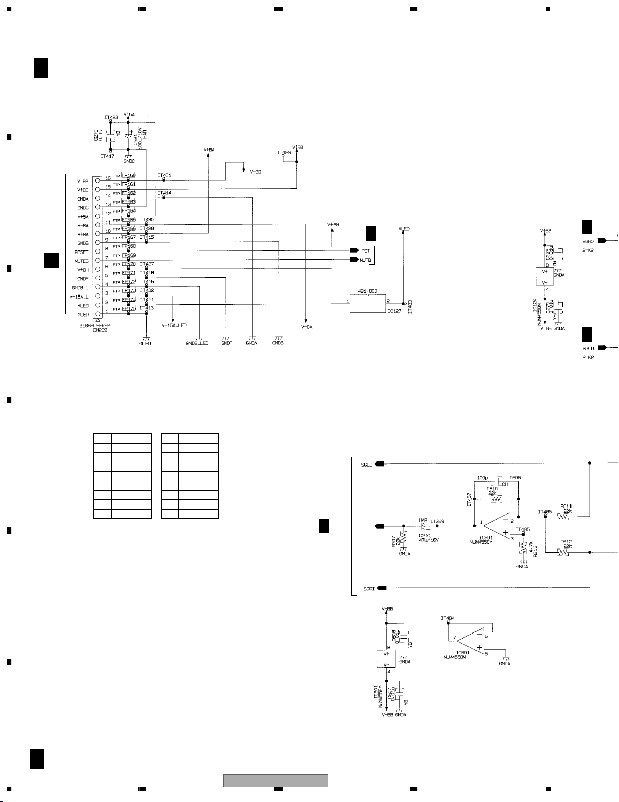
3.21 DSP(3/3) ASSY
A
B
I 3/3
DSP ASSY
I 1/3
I 2/3
CN119
M
C
>
I 2/3
IC124 IC601
No. Voltage (V)
10
D
20
30
4 -15.13
50
60
70
8 14.92
No. Voltage (V)
10
20
30
4 -15.12
50
60
70
8 14.93
I 2/3
E
F
I 3/3
50
1234
DJM-3000
Page 51

5678
A
B
I 2/3
I 2/3
5
C
4
D
I 1/3
I 1/3
I 2/3
DJM-3000
56
C 6/8
CN305
E
F
I 3/3
7
8
51
Page 52

1234
3.22 EFFECT ASSY
A
EFFECT ASSY
J
(226902740)
B
C
J310
C 7/8
D
E
F
J
52
1234
DJM-3000
Page 53

5678
A
B
C
D
E
56
DJM-3000
IC100
No. Voltage (V)
1 1.48
2 0.2
3 0.2
40
5 0.2
6 0.2
7 1.47
8 7.9
F
J
7
8
53
Page 54
1234
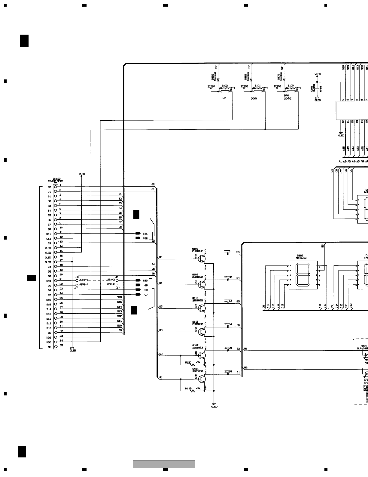
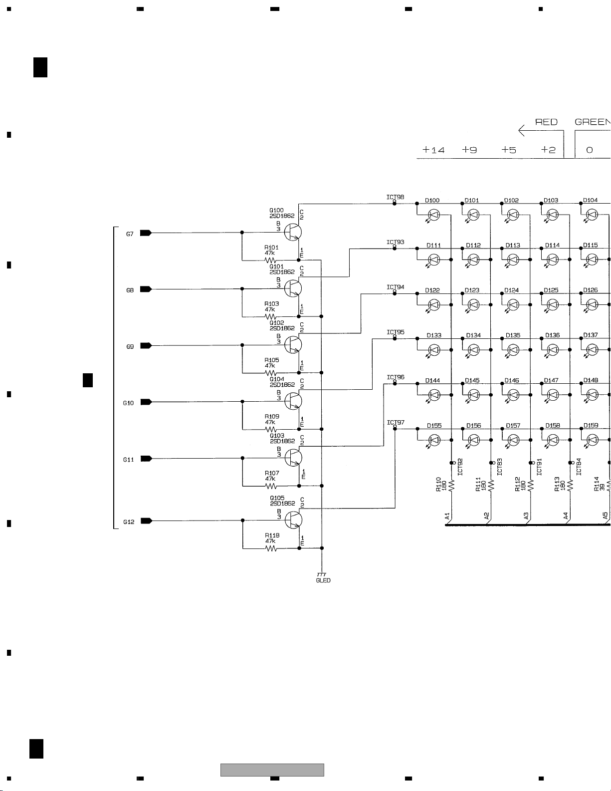
3.23 LED(1/2) ASSY
A
B
C
K 1/2
LED ASSY
(226902720)
K 2/2
CN261
D
I 1/3
K 2/2
E
JUMPER (CONNECTION POINT)
J250-1 ↔ J250-2
J251-1 ↔ J251-2
J252-1 ↔ J252-2
F
K 1/2
54
1234
DJM-3000
Page 55
5678
A
B
K 2/2
C
D
E
56
DJM-3000
F
K 1/2
7
8
55
Page 56
1234
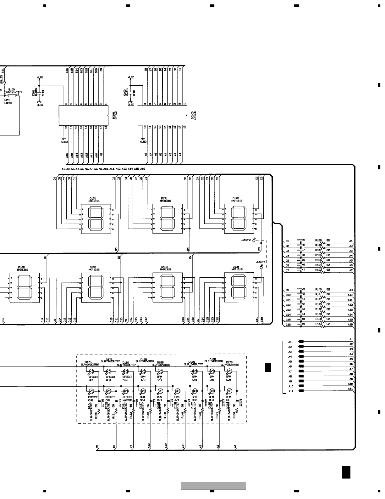
3.24 LED(2/2) ASSY
A
B
C
K 2/2
LED ASSY
(226902720)
K 1/2
D
E
F
K 2/2
56
1234
DJM-3000
Page 57

5678
A
B
C
D
E
56
DJM-3000
K 1/2
F
K 2/2
7
8
57
Page 58
1234
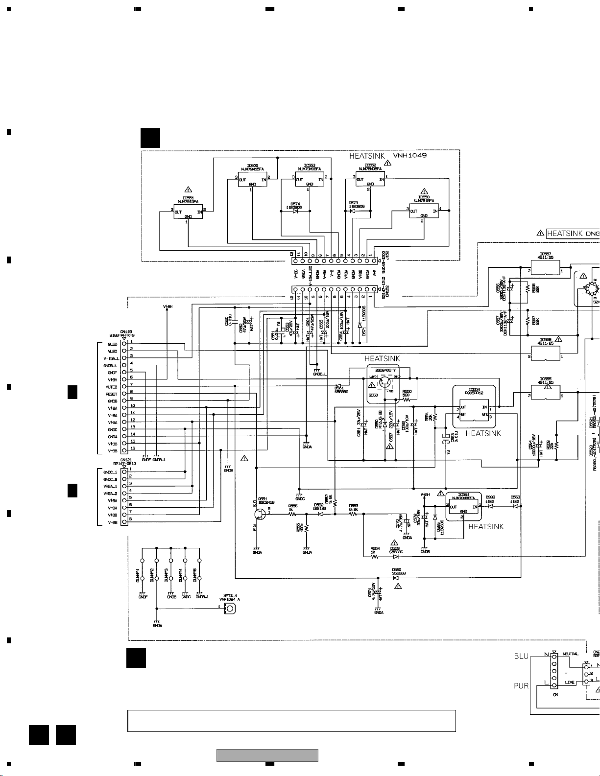
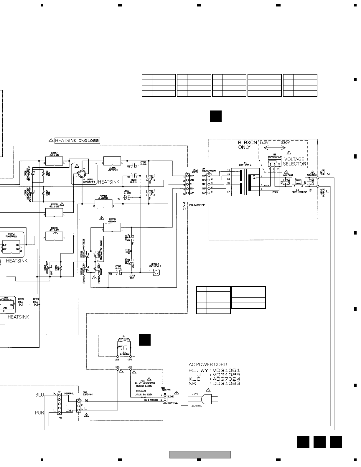
3.25 REG, POWER, TRANS and PSW ASSYS
A
REG ASSY (226902840)
L
B
>
>
>
C
I 3/3
CN209
D
>
>
>
>
E
F
L M
58
A 1/3
J460
>>
>
POWER ASSY
M
(KUCXCN : 226903790)
(WYXCN, RLBXCN : 226902700)
• NOTE FOR FUSE REPLACEMENT
CAUTION -
1234
FOR CONTINUED PROTECTION AGAINST RISK OF FIRE.
REPLACE WITH SAME TYPE AND RATINGS ONLY.
DJM-3000
>
Page 59
5678
A
REG ASSY
IC550 IC551 IC552 IC553 IC600
No. Voltage (V)
1 20.65
20
3 14.99
No. Voltage (V)
10
2 -20.92
3 -15.3
No. Voltage (V)
1 20.65
20
3 7.97
No. Voltage (V)
10
2 -20.99
3 -8.1
No. Voltage (V)
10
2 -20.92
3 -15.2
>
TRANS ASSY
N
B
(KUCXCN, WYXCN : 226902800)
(RLBXCN : 226902801)
>
>
C
>
>
>
>
D
POWER ASSY
>
>>
IC550
No. Voltage (V)
1 8.26
2 5.04
30
4 5.04
IC561
No. Voltage (V)
1 19.3
20
3 8.03
PSW ASSY
>
O
(226902820)
>
56
DJM-3000
E
F
M N O
7
8
59
Page 60

1234
WAVEFORMS
Note : The encircled numbers denote measuring point in the schematic diagram.
A
TERMA ASSY
A
DSP ASSY
I
FTP1
1
V: 1V/div. H: 200µsec/div.
(at LINE1 0dBV input)
CH1PLL
6
V: 0.2V/div. H: 200µsec/div.
RECLA
11
V: 1V/div. H: 200µsec/div.
(at LINE1 0dBV input)
FP32 (SENL)
1
V: 0.5V/div. H: 200µsec/div.
B
CH1LL
2
V: 0.5V/div. H: 200µsec/div.
FTP108
7
V: 20V/div. H: 200µsec/div.
(at MIC2 -50dBV input)
FTP147
12
V: 1V/div. H: 200µsec/div.
(at LINE1 0dBV input)
IT398 (C204)
2
V: 2V/div. H: 200µsec/div.
C
MASTER2L
3
V: 2V/div. H: 200µsec/div.
MIC2
8
V: 0.2V/div. H: 200µsec/div.
FTP156
13
V: 2V/div. H: 200nsec/div.
AINL +
3
V: 2V/div. H: 200µsec/div.
D
FTP81 (MASTER1 OUT L ch)
4
V: 2V/div. H: 200µsec/div.
E
FTP5
5
V: 20V/div. H: 200µsec/div.
(at PHONO1 -40dBV input)
FTP113
9
V: 20V/div. H: 200µsec/div.
(at MIC3 -50dBV input)
C213 − side
10
V: 0.2V/div. H: 200µsec/div.
FTP159
14
V: 0.5V/div. H: 200nsec/div.
FTP159
15
V: 0.5V/div. H: 200nsec/div.
IT371 (SGLI)
4
V: 1V/div. H: 200µsec/div.
IT380 (SGLO)
5
V: 2V/div. H: 500µsec/div.
(PAN [500] DIPTH max)
F
60
1234
DJM-3000
Page 61

5678
TERMB ASSY
B
FT74
1
V: 0.5V/div. H: 200µsec/div.
(at 0dBV input)
RETL
2
V: 1V/div. H: 200µsec/div.
FT68
3
V: 1V/div. H: 200µsec/div.
(at LINE1 0dBV input)
FT104
6
V: 5V/div. H: 200µsec/div.
VR ASSY
C
CFAL
1
V: 0.5V/div. H: 200µsec/div.
ML
2
V: 1V/div. H: 200µsec/div.
MTL1
3
V: 1V/div. H: 200µsec/div.
CH1LA
6
V: 0.2V/div. H: 200µsec/div.
CH1L
7
V: 1V/div. H: 200µsec/div.
MIC1H, L
8
V: 200mV/div. H: 200µsec/div.
(at -40dBV input)
A
B
C
SDL
4
V: 1V/div. H: 200µsec/div.
(at LINE1 0dBV input)
FT107
5
V: 20V/div. H: 200µsec/div.
HP ASSY
P
FTP913 (HSL0)
1
V: 2V/div. H: 200µsec/div.
(at LINE1 -10dBV input)
MTL
4
V: 1V/div. H: 200µsec/div.
HPL1
5
V: 1V/div. H: 200µsec/div.
CH1
CH2
MIC
9
V: 1V/div. H: 200µsec/div.
SGLI
10
V: 1V/div. H: 200µsec/div.
D
E
56
DJM-3000
F
7
8
61
Page 62

1234
VOLTAGES
A
B
C
D
E
TERMA ASSY
A
IC1
No. Voltage (V)
10
20
30
4 -8.1
50
60
70
8 7.95
IC2
No. Voltage (V)
10
20
30
4 -8.1
50
60
70
8 7.94
IC7
No. Voltage (V)
10
20
30
4 -15.29
50
60
70
8 14.97
IC17
No. Voltage (V)
10
20
30
4 -15.29
50
60
70
8 14.96
IC18
No. Voltage (V)
1 1.55
2 1.55
3 1.55
4 -15.29
5 1.55
6 1.55
7 1.55
8 14.96
IC19
No. Voltage (V)
10
20
30
40
50
60
70
8 -15.29
90
10 0
11 0
12 0
13 0
14 0
15 0
16 14.96
IC600
No. Voltage (V)
10
20
30
4 -15.29
50
60
70
8 14.96
TERMB ASSY
B
IC8 IC13 IC15
No. Voltage (V)
1 2.5
2 2.5
3 2.5
40
5 2.48
6 2.48
7 2.48
8 4.99
IC9
No. Voltage (V)
1 2.5
2 2.5
3 2.5
40
5 2.49
6 2.49
7 2.47
8 4.99
IC10
No. Voltage (V)
1 2.52
2 2.46
30
40
5 4.99
6 2.53
7 2.53
8 4.99
IC12
No. Voltage (V)
1 4.99
2 2.46
3 4.99
4 4.99
5 4.99
6 4.99
7 4.99
80
9 4.99
10 4.99
11 2.49
12 2.49
13 2.49
14 2.48
15 0
16 4.99
No. Voltage (V)
1 4.99
2 2.46
3 4.99
4 4.99
5 4.99
6 4.99
70
80
9 4.99
10 0
11 2.49
12 2.49
13 2.49
14 2.49
15 0
16 4.99
IC14
No. Voltage (V)
1 2.46
2 2.5
3 2.35
4 4.98
50
6 2.47
7 2.5
80
9 4.99
10 0
11 0
12 4.99
13 0
14 0
15 0
16 4.99
17 2.46
18 2.48
19 2.49
20 4.99
21 1.58
22 0
23 0
24 4.99
No. Voltage (V)
10
20
30
4 2.49
5 2.48
6 1.58
70
80
9 4.99
10 0
11 0
12 0
13 2.46
14 0
15 2.43
16 2.38
17 0
18 0
19 4.99
20 0
21 0
22 0
23 0
24 2.49
25 0
26 0
27 0
28 4.99
IC16
No. Voltage (V)
10
2 4.99
30
4 4.99
50
6 4.99
70
8 2.49
9 2.49
10 4.99
11 0
12 4.99
13 0
14 4.99
IC101 IC502
No. Voltage (V)
10
20
30
4 -15.28
50
60
70
8 14.97
IC102
No. Voltage (V)
10
20
30
4 -15.29
50
60
70
8 14.97
IC107
No. Voltage (V)
10
20
30
40
5 7.93
67 -8.11
8-
910 11 12 13 7.93
14 7.95
IC500
No. Voltage (V)
10
2 5.02
35
40
5 4.97
60
70
8 4.99
90
10 0
11 5
12 5.02
13 0
14 5.02
No. Voltage (V)
10
20
30
40
50
60
70
80
90
10 0
11 0
12 0
13 0
14 5.02
IC503
No. Voltage (V)
10
20
30
4 -15.29
50
60
70
8 14.96
IC505
No. Voltage (V)
10
20
30
4 -15.29
50
60
70
8 14.96
IC507
No. Voltage (V)
10
2 5.02
3 4.99
4 5.02
50
60
7 4.99
80
90
10 5.02
11 4.99
12 5.02
13 0
14 0
15 4.99
16 5.02
F
62
DJM-3000
1234
Page 63

5678
VR ASSY
C
IC1 IC4 IC10 IC17 IC21 IC29 IC43 IC54
No. Voltage (V)
1 -15.25
20
30
40
50
60
70
80
90
10 0
11 0
12 0
13 0
14 0
15 5
16 0
17 0
18 0
19 0
20 0
21 0
22 0
23 0
24 0
25 0
26 0
27 0
28 14.92
IC3
No. Voltage (V)
1 -15.24
2-
3-
4 -14.99
5 -14.98
6 4.97
70
80
90
10 0
11 0
12 0
13 0
14 0
15 5
16 0
17 0
18 0
19 0
20 0
21 0
22 0
23 4.97
24 4.85
25 4.85
26 -8.08
27 -8.08
28 14.91
No. Voltage (V)
1 7.94
2 0.29
30
40
50
60
780
90
10 11 0
12 -8.09
13 -8.09
14 0
15 0.29
16 7.94
IC5
No. Voltage (V)
1 -15.25
20
30
40
50
60
70
80
90
10 0
11 0
12 0
13 0
14 0
15 5
16 0
17 0
18 0
19 0
20 0
21 0
22 0
23 0
24 0
25 0
26 0
27 0
28 14.92
IC6
No. Voltage (V)
10
20
30
4 -15.24
50
60
70
8 14.9
IC9
No. Voltage (V)
10
20
30
4 -15.25
50
60
70
8 14.93
No. Voltage (V)
10
20
30
4 -15.24
50
60
70
8 14.92
IC11
No. Voltage (V)
10
20
30
4 -15.25
50
60
70
8 14.92
IC12
No. Voltage (V)
10
2 4.97
30
40
50
60
70
8 -15.26
910 0
11 12 0
13 14 0
15 16 14.92
IC13
No. Voltage (V)
10
20
30
4 -15.23
50
60
70
8 14.9
IC16
No. Voltage (V)
10
20
30
4 -15.24
50
60
70
8 14.89
No. Voltage (V)
1 -15.25
20
30
40
50
60
70
80
90
10 0
11 0
12 0
13 0
14 0
15 5.01
16 0
17 0
18 0
19 0
20 0
21 0
22 0
23 0
24 0
25 0
26 0
27 0
28 14.93
IC18
No. Voltage (V)
10
20
30
4 -8.08
50
60
70
8 7.95
IC19
No. Voltage (V)
10
20
30
4 -8.08
50
60
70
8 7.95
IC20
No. Voltage (V)
10
20
30
40
50
60
70
8 -8.09
90
10 0
11 0
12 0
13 0
14 0
15 0
16 7.95
No. Voltage (V)
10
20
30
4 -15.24
50
60
70
8 14.92
IC23
No. Voltage (V)
10
20
30
4 -15.24
50
60
70
8 14.88
IC24
No. Voltage (V)
10
20
30
4 -15.24
50
60
70
8 14.88
IC25
No. Voltage (V)
10
20
30
4 -8.08
50
60
70
8 7.95
IC27
No. Voltage (V)
10
20
30
4 -8.09
50
60
70
8 8.02
IC28
No. Voltage (V)
10
20
30
4 -15.24
50
60
70
8 14.89
No. Voltage (V)
10
20
30
4 -15.24
50
60
70
8 14.89
IC30
No. Voltage (V)
10
20
30
4 -15.24
50
60
70
8 14.89
IC31
No. Voltage (V)
10
20
30
4 -15.24
50
60
70
8 14.89
IC32
No. Voltage (V)
10
20
30
4 -15.24
50
60
70
8 14.89
No. Voltage (V)
1 -15.24
20
30
40
50
60
70
80
90
10 0
11 0
12 0
13 0
14 0
15 5
16 0
17 0
18 0
19 0
20 0
21 0
22 0
23 0
24 0
25 0
26 0
27 0
28 14.9
IC44
No. Voltage (V)
1 -15.24
20
30
40
50
60
70
80
90
10 0
11 0
12 0
13 0
14 0
15 5
16 0
17 0
18 0
19 0
20 0
21 0
22 0
23 0
24 0
25 0
26 0
27 0
28 14.9
IC45
No. Voltage (V)
10
20
30
4 -15.25
50
60
70
8 14.9
No. Voltage (V)
10
20
30
4 -15.24
50
60
70
8 14.89
IC55
No. Voltage (V)
10
20
30
4 -15.24
50
60
70
8 14.89
IC56
No. Voltage (V)
10
20
30
4 -15.24
50
60
70
8 14.9
IC59
No. Voltage (V)
10
20
30
4 -15.24
50
60
70
8 14.91
IC63
No. Voltage (V)
1 4.28
23 -8.09
4 -8.1
56 -8.1
7 -8.1
8 -8.1
9 7.9
10 7.9
11 7.9
12 -8.09
13 -4.5
14 -4.46
15 4.3
16 7.94
A
B
C
D
E
F
56
DJM-3000
7
8
63
Page 64
1234
A
B
C
D
E
IC64 IC71 IC700
No. Voltage (V)
1 0.3
23 -8.1
4 -8.1
56 -8.1
7 -8.1
8 -8.1
9 7.8
10 7.8
11 7.9
12 -8.09
13 0
14 0
15 0
16 7.93
IC65
No. Voltage (V)
1 4.29
20
30
4 -8.1
50
60
70
8 4.98
IC66
No. Voltage (V)
1 -15.24
20
30
40
50
60
70
80
90
10 0
11 0
12 0
13 0
14 0
15 5
16 0
17 0
18 0
19 0
20 0
21 0
22 0
23 0
24 0
25 0
26 0
27 0
28 14.91
IC67
No. Voltage (V)
10
20
30
4 -15.26
50
60
70
8 14.92
No. Voltage (V)
1 7.92
2 2.47
3 3.72
40
5 1.23
6 2.47
70
8 4.98
IC72
No. Voltage (V)
10
20
30
4 -15.24
50
60
70
8 14.9
IC74
No. Voltage (V)
10
20
30
4 -15.24
50
60
70
8 14.89
IC76
No. Voltage (V)
1 1.2 to 2
20
3 1.2 to 2
40
50
60
70
8 1 to 2
90
10 0
11 0
12 0
13 0
14 4.96
IC78
No. Voltage (V)
1 5.01
20
3 4.96
4-
5-
6 4.96
70
80
9 0.3
10 0
11 4.96
12 13 14 4.96
15 0
16 4.96
No. Voltage (V)
10
20
30
40
50
60
70
8 -15.24
90
10 0
11 0
12 7.92
13 0
14 0
15 0
16 14.89
IC703
No. Voltage (V)
10
20
30
4 -15.24
50
60
70
8 14.9
IC704
No. Voltage (V)
10
20
30
4 -15.24
50
60
70
8 14.9
F
64
1234
DJM-3000
Page 65

5678
DSP ASSY
I
IC108 IC119
No. Voltage (V) No. Voltage (V) No. Voltage (V) No. Voltage (V)
1 0 to 5.06 21 0 to 5.06 41 0 to 5.06 61 0 to 5.06
2 0 to 5.06 22 0 to 5.06 42 0 to 5.06 62 0 to 5.06
3 0 to 5.06 23 0 to 5.06 43 0 to 5.06 63 0 to 5.06
4 0 to 5.06 24 0 to 5.06 44 0 to 5.06 64 0 to 5.06
5 0 to 5.06 25 0 to 5.06 45 0 to 5.06 65 0 to 5.06
6 0 to 5.06 26 0 to 5.06 46 0 to 5.06 66 0 to 5.06
7 0 to 5.06 27 0 to 5.06 47 0 to 5.06 67 0 to 5.06
8 5.06 28 0 to 5.06 48 0 68 0 to 5.06
9 0 to 5.06 29 5.06 49 0 to 5.06 69 0 to 5.06
10 0 to 5.06 30 5.06 50 0 to 5.06 70 0 to 5.06
11 0 to 5.06 31 0 51 0 to 5.06 71 0
12 0 to 5.06 32 0 to 5.06 52 5.06 72 0 to 5.06
13 0 to 5.06 33 0 53 0 to 5.06 73 0 to 5.06
14 0 to 5.06 34 0 to 5.06 54 0 to 5.06 74 0 to 5.06
15 0 to 5.06 35 0 to 5.06 55 0 to 5.06 75 0 to 5.06
16 0 to 5.06 36 0 to 5.06 56 0 to 5.06 76 0 to 5.06
17 0 to 5.06 37 0 to 5.06 57 0 to 5.06 77 0 to 5.06
18 0 to 5.06 38 0 to 5.06 58 0 to 5.06 78 0 to 5.06
19 0 to 5.06 39 0 to 5.06 59 0 to 5.06 79 0 to 5.06
20 0 40 0 to 5.06 60 0 to 5.06 80 0 to 5.06
No. Voltage (V) No. Voltage (V) No. Voltage (V) No. Voltage (V)
1 3.45 26 0 to 3.45 51 0 to 3.45 76 0 to 3.45
2 0 27 0 to 3.45 52 0 to 3.45 77 0 to 3.45
3 3.45 28 0 53 0 to 3.45 78 0 to 3.45
4 0 to 3.45 29 0 to 3.45 54 0 to 3.45 79 3.45
5 0 30 0 55 3.45 80 0
6 0 to 3.45 31 3.45 56 0 81 0 to 3.45
7 0 32 0 to 3.45 57 0 to 3.45 82 0 to 3.45
8 3.45 33 0 58 0 to 3.45 83 0 to 3.45
9 0 34 3.45 59 0 to 3.45 84 0 to 3.45
10 2.5 35 3.45 60 0 to 3.45 85 0
11 3.45 36 0 61 3.45 86 0
12 0 37 3.45 62 0 87 3.45
13 0 38 0 63 3.45 88 0
14 0 to 3.45 39 0 to 3.45 64 0 89 3.45
15 3.45 40 0 to 3.45 65 0 90 0
16 0 41 0 to 3.45 66 3.45 91 0
17 0 42 3.45 67 0 92 3.45
18 0 43 0 68 0 93 0
19 0 44 0 69 0 94 0
20 0 to 3.45 45 0 to 3.45 70 0 95 0
21 3.45 46 0 to 3.45 71 3.45 96 0
22 0 47 0 to 3.45 72 0 97 0
23 5 48 3.45 73 0 98 1.7
24 0 to 3.45 49 0 74 0 99 1.7
25 0 to 3.45 50 0 to 3.45 75 0 to 3.45 100 3.45
A
B
IC101
No. Voltage (V)
10
20
30
4 -15.13
5 15.12
60
70
8 14.93
IC102
No. Voltage (V)
1 0.35
2 0.35
3 0.35
4 -15.12
5 0.35
6 0.35
7 0.35
8 14.92
IC105
No. Voltage (V)
1 0.35
2 0.35
3 0.35
4 -15.13
5 0.35
6 0.35
7 0.35
8 14.92
IC106
No. Voltage (V)
1 0.35
2 0.35
3 0.35
4 -15.13
5 0.35
6 0.35
7 0.35
8 14.91
IC109
No. Voltage (V)
1 2.5
2 1.5
3 1.51
4 1.68
5 2.54
60
70
80
9 4.18
10 4.18
11 4.18
12 3.04
13 0
14 0
15 2.33
16 5.04
IC110
No. Voltage (V)
10
20
30
40
50
60
70
80
9 4.2
10 4.2
11 4.2
12 0
13 0
14 0
15 0
16 5.04
IC111
No. Voltage (V)
1 5.05
2 0 to 5.05
3 0 to 5.05
4 5.05
5 0 to 5.05
60
70
80
90
10 5.05
11 0
12 0
13 5.05
14 5.05
IC113 IC115 IC122 IC600
No. Voltage (V)
1 3.45
20
30
40
50
6 3.45
7 3.45
80
9 3.45
10 3.45
11 3.45
12 3.45
13 3.45
14 3.45
15 0
16 3.45
17 3.45
18 3.45
19 3.45
20 3.45
21 3.45
22 3.45
23 3.45
24 0
25 0
26 0
27 0
28 0
IC114
No. Voltage (V)
1 1.72
2 2.52
3 1.72
4 2.52
50
60
70
80
90
10 0
11 0
12 0
13 0
14 5.04
IC116
No. Voltage (V)
1 2.48
2 2.48
3 2.48
40
5 2.5
6 2.5
7 2.5
8 4.98
No. Voltage (V)
1 -15
20
30
40
50
60
70
80
90
10 0
11 0
12 0
13 0.5
14 0
15 5
16 0.6
17 0
18 0
19 0
20 0
21 0
22 0
23 0
24 0
25 0
26 0
27 0
28 14.96
No. Voltage (V)
1 4.96
20
3 2.48
4 2.48
5 2.48
6 2.48
7 4.96
80
90
10 4.96
11 5.06
12 5.06
13 5.06
14 0
15 2.48
16 5.06
17 0
18 0
19 0
20 0
21 5.06
22 0
23 5.06
24 5.06
25 5.06
26 4.06
27 4.06
28 2.48
No. Voltage (V)
10
20
3 5.01
4 5.01
5 5.01
60
70
80
9 4.21
10 0
11 0
12 0
13 0
14 0
15 0
16 5.06
C
D
E
F
56
DJM-3000
7
8
65
Page 66
1234
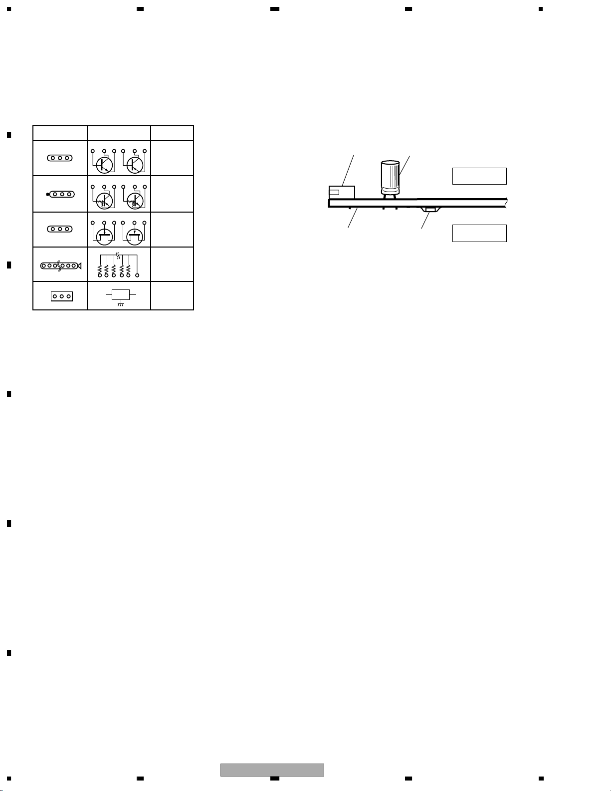
4. PCB CONNECTION DIAGRAM
A
NOTE FOR PCB DIAGRAMS :
1. Part numbers in PCB diagrams match those in the schematic
diagrams.
2. A comparison between the main parts of PCB and schematic
diagrams is shown below.
Symbol In PCB
Diagrams
BCE
B
BCE
D
Symbol In Schematic
Diagrams
BCEBCE
BCE
DGGSS
BCE
DGS
Part Name
Transistor
Transistor
with resistor
Field effect
transistor
Resistor array
3-terminal
regulator
3. The parts mounted on this PCB include all necessary parts for
several destinations.
For further information for respective destinations, be sure to
check with the schematic diagram.
4. View point of PCB diagrams.
Connector
Capacitor
SIDE A
P.C.Board
Chip Part
SIDE B
C
D
E
F
66
DJM-3000
1234
Page 67
5678
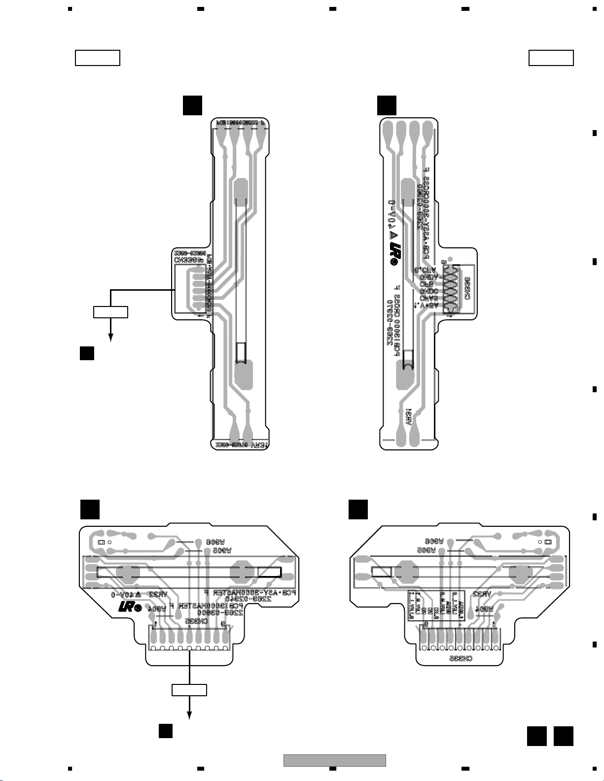
4.1 CF and MAF ASSYS
SIDE A SIDE B
CN336
CF ASSY(226902960)
D
CF ASSY(226902960)
D
A
B
C
J306
C
MAF ASSY(226902940)
F
MAF ASSY(226902940)
F
D
E
CN335
CN3005
C
56
DJM-3000
F
FD
7
8
67
Page 68
1234
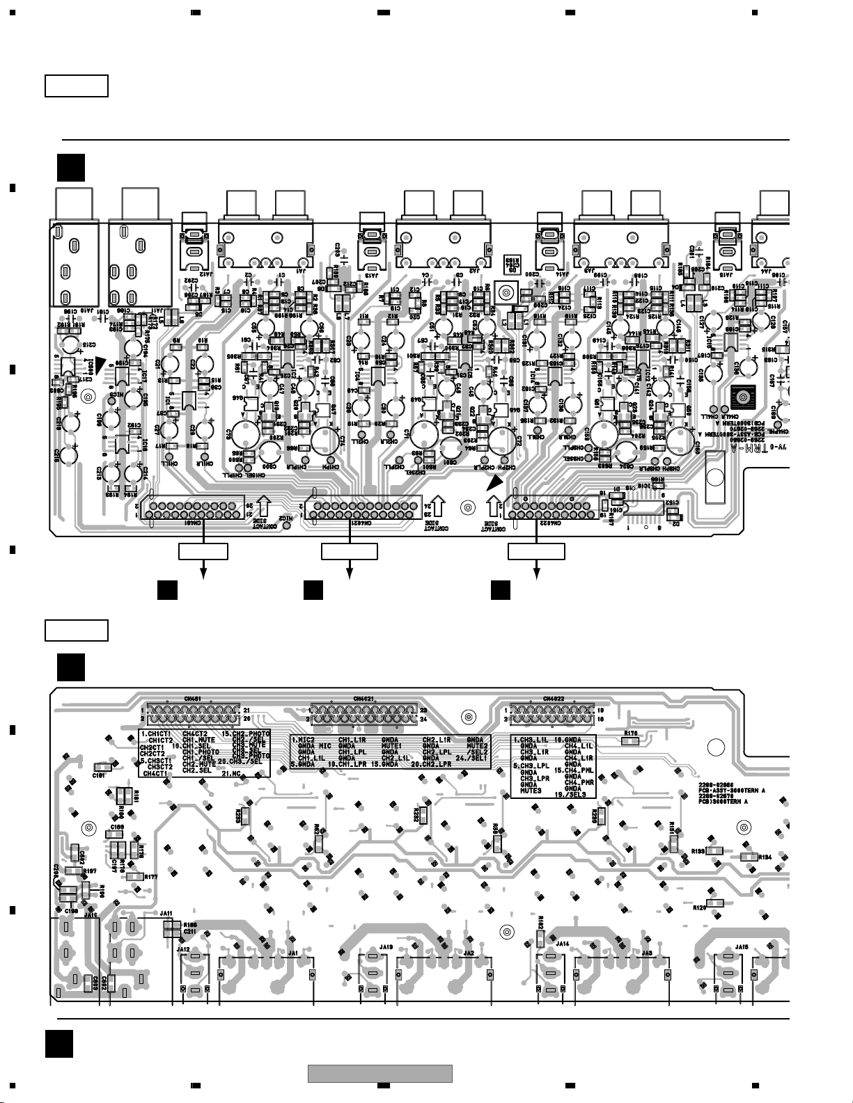
4.2 TERMA ASSY
SIDE A
A
IC600
A
B
IC17
IC18
TERMA ASSY (226902660)
IC1
IC2
Q47Q46 Q19 Q20
IC4
IC5
Q21 Q22 Q48Q49
IC14
Q51 Q23 Q24 Q50
IC19
IC15IC12
C
D
E
CN481
CN581
B
SIDE B
TERMA ASSY (226902660)
A
CN4021
CN3021
C
CN4022
CN3022
C
F
A
68
1234
DJM-3000
Page 69

5678
IC15
IC16 Q3 Q4
Q7 Q8
CN401
J460
IC7 Q508 Q501
Q511 Q507
IC502
CN480
CN580
B
IC501 IC500
CN482
CN582
B
SIDE A
A
B
C
C
CN301
M
CN121
SIDE B
D
E
VR201
56
Q5
Q1
Q6
Q2
DJM-3000
F
Q507Q511
Q501Q508
A
7
8
69
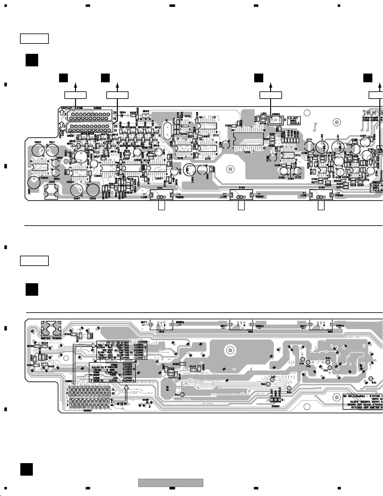
Page 70
1234
N
4.3 TERMB ASSY
SIDE A
A
TERMB ASSY (226902680)
B
CN260
I
CN583
B
C
IC501
Q501
Q506Q509
Q521
IC500 IC502 IC506 IC507
CN481
A
CN581
Q507 Q515 Q500 IC10 IC12 IC15 IC14
Q505 Q514 Q513 Q508Q520Q511Q512 IC16 IC13Q516Q502
Q510 Q503 Q519Q504 Q517Q518
A
CN582
CN482
IC9 IC8
C
C
CN5
D
E
SIDE B
TERMB ASSY (226902680)
B
Q500
F
B
70
1234
DJM-3000
Page 71
5678
4
C
CN510
CN350
A
CN580
CN480
SIDE A
A
B
C
VR101
IC9 IC8
IC503
Q528
Q525
IC505 IC504 Q117
Q524 Q526
Q527 Q523
Q522
Q529
IC101
Q116 Q101
Q114
Q115
IC107
IC102
SIDE B
D
Q527
Q529Q523Q524
Q114 – Q117
Q101Q522Q526IC504IC505
E
VR101
IC503
Q525
Q528
56
DJM-3000
F
B
7
8
71
Page 72
1234
N
C
3
N
4.4 VR, CFCURV, MIC, EFFECT and HP ASSYS
SIDE A
A
Q19
Q700 Q20 Q22
Q21IC55
IC101
MIC ASSY (226902780)
B
C
H
IC54
IC28
IC32IC700IC71
Q701
CN4021
A
CN3021
Q26IC29 Q703
Q25
Q24IC33
Q23 IC37
Q702
CN4022
A
CN3022
Q27 Q704
IC38
IC41 IC42
Q29IC34
Q705
Q28 IC39 IC49 IC52
Q30
Q817
IC53 IC2
IC4
A
C
CN
D
E
F
C E H
72
CFCURV
E
J306
CN304
CN3001
CN3002
CN3003
CN
ASSY
(226903700)
CN336
D
1234
DJM-3000
CN204
I
G
CN331
(CH1)
G
CN331
(CH2)
G
CN331
(CH3)
G
C
(
Page 73

5678
28 IC39 IC49 IC52
Q817
IC53 IC2
IC4
A
CN301
CN401
SIDE A
IC13 IC16IC50
IC74
IC702
IC78
IC23
IC24
Q17
IC20
C
IC27
IC26
Q9 Q10
VR
A
B
ASSY
(226903690)
EFFECT
J
ASSY
(226902740)
C
CN3003
CN331
(CH3)
CN3004
CN331
G
(CH4)
56
CN3005
CN335
F
CN305
CN205
I
DJM-3000
D
E
HP
P
ASSY
F
(226902760)
C J P
7
8
73
Page 74

A
1234
SIDE B
IC51
IC3
Q2 Q4 Q6 Q8
Q1 Q3 Q5 Q7
IC2 IC4
IC48 IC47
IC1
IC10
IC40
Q31
IC25 IC27
IC26
IC100IC18
IC19 Q812 Q810
Q805
IC75IC701
Q804
IC79
IC17 IC12
Q816
Q814Q801Q802
Q809
Q800 Q806
Q803
Q800
IC76
B
CN510
Q807 IC66
IC67
IC11 IC9 IC5
IC21
CN350
B
C
VR
ASSY
(226903690)
EFFECT
J
ASSY
(226902740)
C
D
E
HP
P
ASSY
CN371
(226902760)
F
CN262
I
C J P
74
1234
DJM-3000
Page 75

5678
IC51
IC3
Q6 Q8
Q5 Q7
IC2 IC4
IC48 IC47
IC1
IC10
Q31
IC40
IC44
Q815
IC35
IC36
IC63
IC46
Q813
IC45
IC30
IC31
IC43
IC72
IC8
IC73IC64 Q38IC65
IC7
IC56Q811 IC57
IC60IC59IC6
MIC ASSY
H
(226902780)
SIDE B
IC703
IC704
A
B
C
CFCURV
E
ASSY
(226903700)
D
E
F
56
DJM-3000
C E H
7
8
75
Page 76

1234
4.5 DSP ASSY
SIDE A
A
M
CN119
B
C
D
DSP ASSY
I
(226902640)
CN209
E
IC114
IC113
IC127
Q112
IC120
IC119
Q111
IC108
IC112 IC126
F
IC109
Q110
IC122
IC123IC118
I
76
1234
DJM-3000
Page 77

5678
B
CN583
CN260
SIDE A
A
B
C
IC114 IC110IC121
IC122
IC123IC118
IC115
C
CN204
CN304
D
E
56
DJM-3000
F
I
7
8
77
Page 78

A
1234
SIDE B
B
C
D
DSP ASSY
I
(226902640)
E
Q105 Q104 Q103 Q102 Q109 Q108 Q107 Q106
F
IC103
IC102
IC105IC106
IC121
IC101
IC501
IC124 IC125
I
78
1234
DJM-3000
Page 79

5678
C
CN305
CN205
K
CN100
CN261
SIDE B
A
B
C
501
IC124 IC125
IC127
IC600
IC111
CN371
C
D
CN262
E
F
56
DJM-3000
I
7
8
79
Page 80
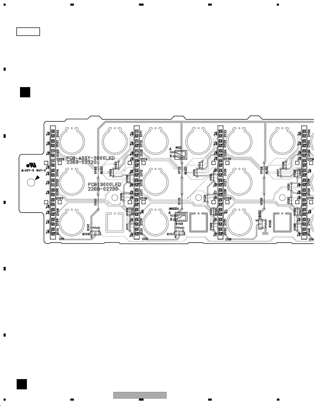
1234
4.6 LED ASSY
SIDE A
A
LED ASSY
K
B
C
D
(226902720)
E
F
K
80
1234
DJM-3000
Page 81
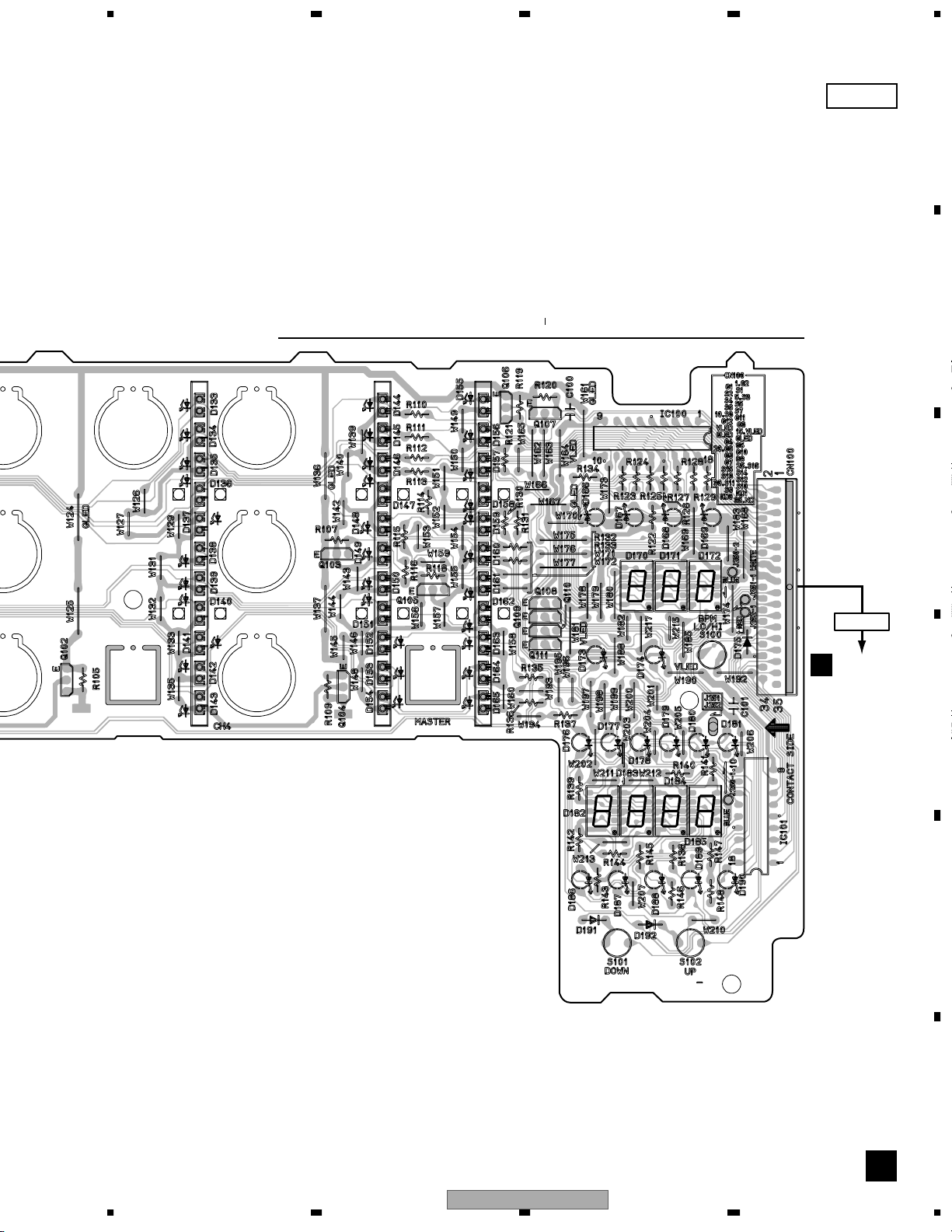
5678
Q104
Q105 Q107
Q106Q103
Q111
IC100 IC101
SIDE A
A
B
C
CN100
CN261
I
D
E
56
DJM-3000
F
K
7
8
81
Page 82
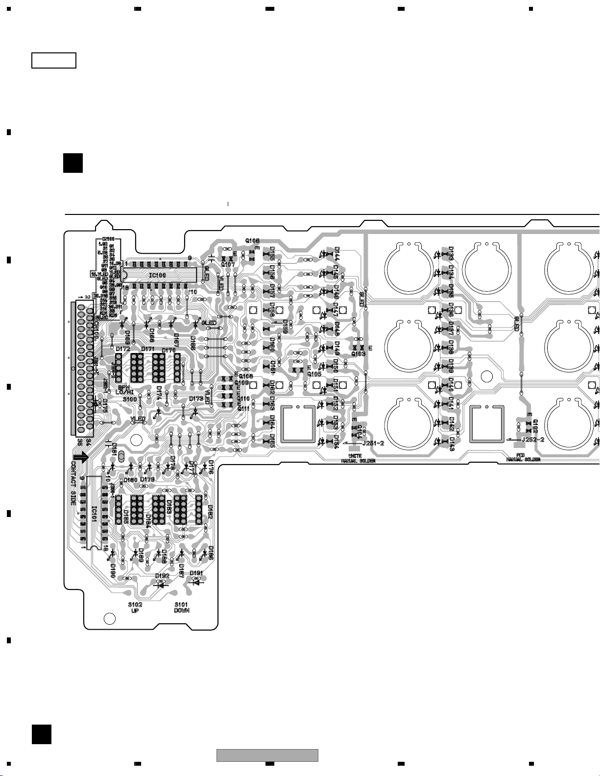
A
1234
SIDE B
LED ASSY
K
B
IC101
C
(226902720)
IC100
Q107
Q111
Q106
Q105 Q103
Q104
Q102
D
E
F
82
K
DJM-3000
1234
Page 83
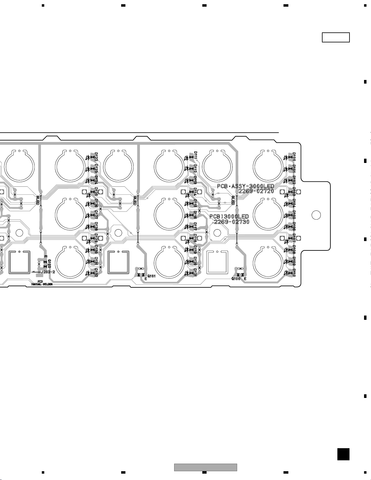
5678
Q102 Q101 Q100
SIDE B
A
B
C
D
E
F
56
DJM-3000
K
7
8
83
Page 84

1234
4.7 REG, POWER, TRANS and PSW ASSYS
SIDE A
A
IC550 IC552 IC553 IC600 IC551
J152
B
PSW
O
ASSY
(226902820)
REG
L
ASSY
(226902840)
I
CN209
CN119
C
CN152
D
CN121
A
J460
POWER ASSY
M
(226903790)
J32
J31J21
J22
CN1
CN1
CN2
CN2
CN4
LIVE
NEUTRAL
AC IN
E
F
L M N O
84
IC551 IC557
CONNECTOR
ASSY
1
2
3
4
5
1234
Q550 IC554
IC556
N
J101
J102
TRANS ASSY
DJM-3000
Q551
IC555
IC558 IC559
IC560
(226902800)
J4
Page 85

5678
REG
L
ASSY
(226902840)
O
(226902820)
POWER ASSY
M
IC600IC551
PSW
ASSY
SIDE B
A
IC550IC552IC553
B
(226903790)
C
TRANS ASSY
N
(226902800)
Q551IC560 IC555
IC558IC559
D
Q550
IC556IC554
IC557
IC561
E
F
56
DJM-3000
L M N O
7
8
85
Page 86
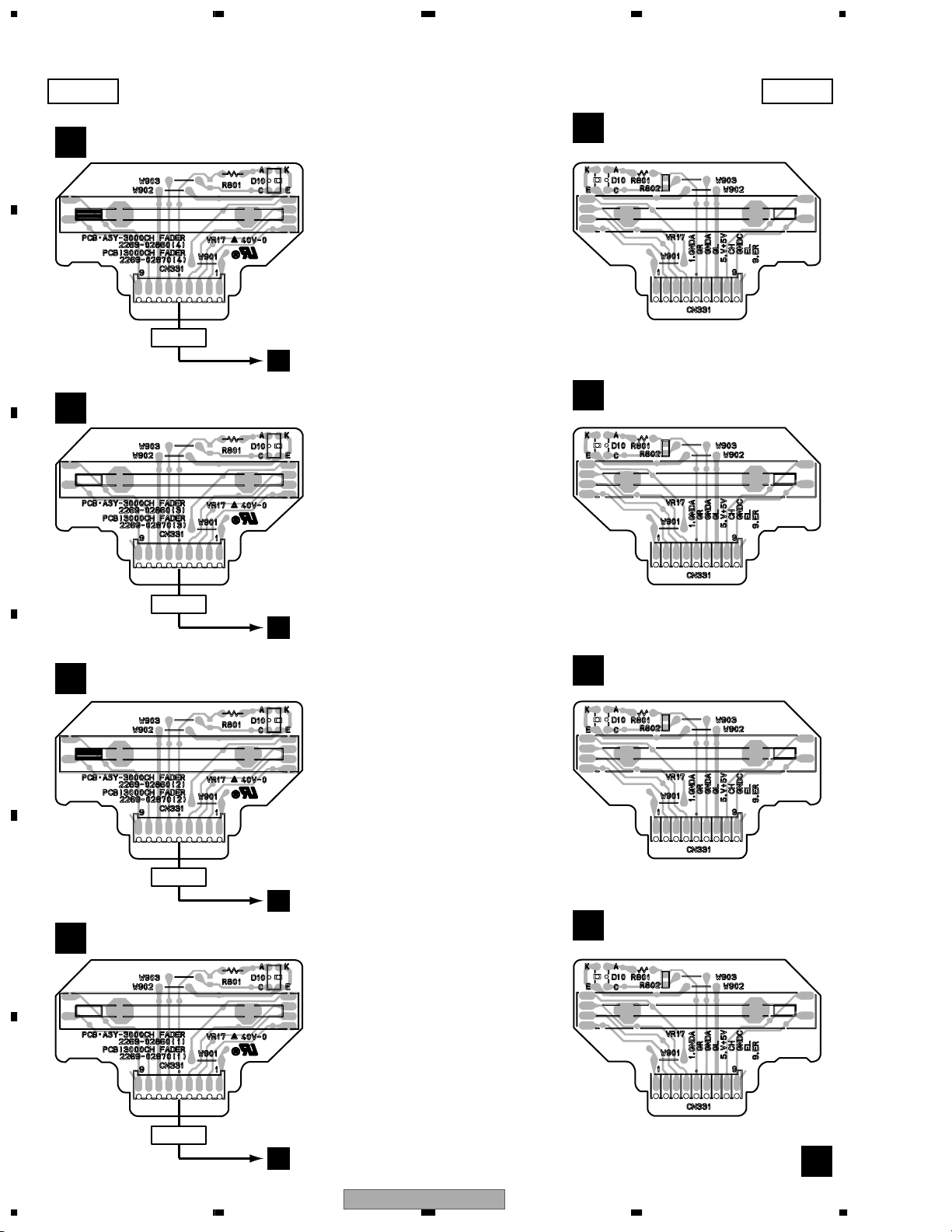
1234
4.8 CHF1 to CHF4 ASSYS
SIDE A SIDE B
A
CHF4 ASSY
CHF4 ASSY
G
B
CN331
CHF3 ASSY
G
(226902860CH4)
CN3004
C
(226902860CH3)
G
(226902860CH4)
CHF3 ASSY
G
(226902860CH3)
C
CN331
CN3003
C
CHF2 ASSY
CHF2 ASSY
G
D
CN331
E
CHF1 ASSY
G
(226902860CH2)
CN3002
C
(226902860CH1)
G
(226902860CH2)
CHF1 ASSY
G
(226902860CH1)
F
CN331
CN3001
86
C
DJM-3000
1234
G
Page 87

5678
5. PCB PARTS LIST
NOTES:
Parts marked by "NSP" are generally unavailable because they are not in our Master Spare Parts List.
The mark found on some component parts indicates the importance of the safety factor of the part.
Therefore, when replacing, be sure to use parts of identical designation.
When ordering resistors, first convert resistance values into code form as shown in the following examples.
Ex.1 When there are 2 effective digits (any digit apart from 0), such as 560 ohm and 47k ohm (tolerance is shown by J=5%,
and K=10%).
560 Ω
47k Ω
0.5 Ω
1 Ω
56 x 10
47 x 10
R50
1R0
1
3
561
473
RD1/4PU J
RD1/4PU J
RN2H K
RS1P K
Ex.2 When there are 3 effective digits (such as in high precision metal film resistors).
5.62k Ω
1
5621
RN1/4PC F562 x 10
LIST OF WHOLE PCB ASSEMBLIES
Mark Symbol and Description
TERM ASSY 226902660 226902660 226902660
TERMA ASSY 226902660 226902660 226902660
TERMB ASSY 226902680 226902680 226902680
NSP VR ASSY 226100980 226100980 226100980
VR ASSY 226903690 226903690 226903690
NSP CFCURV ASSY 226903700 226903700 226903700
NSP EFFECT ASSY 226902740 226902740 226902740
NSP MIC ASSY 226902780 226902780 226902780
NSP HP ASSY 226902760 226902760 226902760
DJM-3000/
KUCXCN
DJM-3000/WYXCN
DJM-3000/
RLBXCN
A
561
473
R50
1R0
5621
B
C
DSP ASSY 226902640 226902640 226902640
NSP SUB ASSY 226101022 226101020 226101020
CF ASSY 226902960 226902960 226902960
MAF ASSY 226902940 226902940 226902940
CHF1 ASSY 226902860CH1 226902860CH1 226902860CH1
CHF2 ASSY 226902860CH2 226902860CH2 226902860CH2
CHF3 ASSY 226902860CH3 226902860CH3 226902860CH3
CHF4 ASSY 226902860CH4 226902860CH4 226902860CH4
LED ASSY 226902720 226902720 226902720
REG ASSY 226902840 226902840 226902840
POWER ASSY 226903790 226902700 226902700
TRANS ASSY 226902800 226902800 226902800
PSW ASSY 226902820 226902820 226902820
TRANS ASSY
N
Mark Symbol and Description 226902800 226902801
S2 Voltage Selector Not used DSA1026
D
E
POWER ASSY
M
Although 226902700 and 226903790 are different in part number,
they consist of the same components.
56
DJM-3000
F
7
8
87
Page 88

1234
Mark No. Description Part No.
A
TERMA ASSY
A
SEMICONDUCTORS
IC12,IC16,IC17,IC2,IC5 NJM2068M
IC600 NJM2068M
IC1,IC14,IC15,IC18,IC4 NJM4580M
IC502,IC7 NJM4580M
IC46-IC51 PC357N1
IC500,IC501 TC74HCU04AF
IC19 TC9215AF
Q501,Q507,Q508,Q511 2SC2878
Q1,Q19,Q2,Q20-Q24 2SC3326
B
Q3-Q8 2SC3326
D1-D6 1SS355
COILS
L702,L703,L705,L706 922607040
>
L600 LRCA101J
L9,L10 PTL1003
L1-L8 (Puls Trans) VTL1105
CAPACITORS
C198,C208 CCSQCH101J50
C197 CCSQCH220J50
C
D
E
F
C10,C102,C103,C11 CCSRCH101J50
C110-C119,C12,C120-C125 CCSRCH101J50
C13-C18,C186,C19,C193 CCSRCH101J50
C20,C5-C9,C92-C97 CCSRCH101J50
C217 CCSRCH220J50
C605,C606 CEAT471M16
C195 CEJQ100M16
C127,C128,C131,C132 CEJQ100M50
C135-C138,C145,C146 CEJQ100M50
C157,C158,C169,C170,C194 CEJQ100M50
C199,C21,C213-C216,C218 CEJQ100M50
C22-C24,C27-C30,C509 CEJQ100M50
C51,C518,C52,C523,C532 CEJQ100M50
C55,C56,C83-C90 CEJQ100M50
C701 CEJQ101M10
C141,C142,C153,C154 CEJQ220M25
C45-C48 CEJQ220M25
C159,C160,C71-C74 CEJQ330M50
C520,C527 CEJQ470M16
C600,C601,C604 CEJQNP330M25
C508,C522,C534,C536 CEJQNPR33M50
C75,C76,C79,C80 CEJQNPR33M50
C1,C104-C109,C181,C196 CKCYF103Z50
C2-C4 CKCYF103Z50
C177,C178,C200-C203,C91 CKCYF473Z50
C189,C191,C211,C602 CKSQYB103K50
C802,C803 CKSQYB103K50
C519,C526,C529,C530,C700 CKSQYB104K25
C151,C152,C175,C176 CKSRYB103K50
C182-C185,C187,C188,C190 CKSRYB103K50
C192,C204-C207,C209,C210 CKSRYB103K50
C212,C25,C26,C31,C32 CKSRYB103K50
C37,C38,C49,C50,C506 CKSRYB103K50
C514,C603,C69,C70 CKSRYB103K50
C98-C101 CQMA152J50
C57,C58,C61,C62,C149 CQMA222J50
C150,C163,C164 CQMA222J50
88
1234
Mark No. Description Part No.
C65-C68,C155,C156,C167,C168 CQMA681J50
RESISTORS
R190 RN1/10SE1000D
R180,R181 RN1/10SE1001D
R120,R177,R197 RN1/10SE1003D
R176 RN1/10SE1201D
R151,R178,R58,R62 RN1/10SE1203D
R144,R145,R156,R157 RN1/10SE4703D
R45,R46,R49,R50 RN1/10SE4703D
R300-R315 RN1/10SE7503D
R1,R104,R105,R108-R111 RN1/16SE1000D
R173,R2,R5,R6 RN1/16SE1000D
R96-R99 RN1/16SE1000D
R136,R139,R148,R149 RN1/16SE1001D
R33,R34,R37,R38 RN1/16SE1001D
R123,R126,R127,R13-R16 RN1/16SE1003D
R507,R509,R542,R553 RN1/16SE1003D
R79-R82,R92-R95 RN1/16SE1003D
R195 RN1/16SE1201D
R150,R162,R163,R196,R57 RN1/16SE1203D
R61 RN1/16SE1203D
R10,R11,R114,R115 RN1/16SE1302D
R118,R119,R12,R9 RN1/16SE1302D
R106,R107,R112,R113,R174 RN1/16SE1502D
R191,R3,R4,R546,R548 RN1/16SE1502D
R7,R71,R72,R8 RN1/16SE1502D
R164,R165,R193,R194 RN1/16SE2002D
R140,R141,R152,R153,R175 RN1/16SE3301D
R192,R39-R42 RN1/16SE3301D
R516,R535,R545,R549 RN1/16SE4300D
R83-R90 RN1/16SE4300D
R539,R561,R75,R76 RN1/16SE4302D
R116,R117,R124,R125 RN1/16SE5602D
R198,R199,R31,R32 RN1/16SE5602D
R523,R524,R526,R528,R705 RS1/10S0R0J
R708,R710,R711 RS1/10S0R0J
R170 RS1/10S102J
R703,R704 RS1/10S122J
R232,R233,R239 RS1/10S152J
R182,R186 RS1/10S471J
R168,R169 RS1/10S750J
R100,R101,R67,R68 RS1/10S912J
VR201 (10kB) DCS1056
Other Resistors RS1/16S###J
OTHERS
J460 CONNECTOR ASSY 226404700
JA10 YKB CONNECTOR 950001790
JA11 YKB CONNECTOR 950001800
CN1-CN4,CN9 4P PIN JACK AKB7015
CN482 CONNECTOR B3B-XH-A
JA8 2P PIN JACK (ORG) DKB1027
CN401 FFC CONNECTOR 12P HLEM12S-1
CN480 FFC CONNECTOR 15P HLEM15S-1
CN4022 FFC CONNECTOR 19P HLEM19S-1
CN481 FFC CONNECTOR 21P HLEM21S-1
CN4021 FFC CONNECTOR 24P HLEM24S-1
JA12-JA15 REMOTE CON. JACK RKN1004
JA7 2P PIN JACK VKB1031
DJM-3000
Page 89

5678
Mark No. Description Part No.
TERMB ASSY
B
SEMICONDUCTORS
IC14 AK5351-VF
IC107 BU4066BCF
IC12,IC16,IC17,IC2,IC5 NJM2068M
IC600 NJM2068M
IC8,IC9 NJM2100M
IC503-IC505 NJM4556AL
IC101,IC102 NJM4558M
IC1,IC14,IC15,IC18,IC4 NJM4580M
IC502,IC7 NJM4580M
IC506,IC507 TC74HC123AF
IC500,IC501 TC74HC14AF
IC12,IC13 TC74HC163AF
IC502 TC74HC86AF
IC500,IC501 TC74HCU04AF
IC10 TC7WU04F
IC19 TC9215AF
IC15 TC9271F
Q500 2SC1740S
Q114-Q117,Q501,Q507,Q508 2SC2878
Q511,Q522-Q529 2SC2878
Q1,Q19,Q2,Q20-Q24 2SC3326
Q3-Q8 2SC3326
Q506-Q509,Q511-Q513,Q515 DTA114EK
Q520 DTA114EK
Q101 DTA124ES
Q501-Q505,Q510,Q514 DTC114EK
Q516-Q519,Q521 DTC114EK
D504 1SS133
D1-D5,D500-D503 1SS355
D505-D517,D6 1SS355
SWITCH
S101 945001240
COILS
L101,L102,L600,L600 LRCA101J
L1-L8 (Chip Beads BK2125LM252) VTL1105
CAPACITORS
C108-C115,C198,C208 CCSQCH101J50
C197 CCSQCH220J50
C10,C102,C103,C11 CCSRCH101J50
C110-C119,C12,C120-C125 CCSRCH101J50
C13-C18,C186,C19,C193 CCSRCH101J50
C20,C5-C9,C92-C97 CCSRCH101J50
C173,C174 CCSRCH150J50
C514,C515,C517,C522 CCSRCH151J50
C525,C526,C532,C533 CCSRCH151J50
C217 CCSRCH220J50
C120-C123,C179-C182 CCSRCH270J50
C605,C606 CEAT471M16
C164-C166,C168,C169,C172 CEJQ100M16
C195,C602,C604,C608-C611 CEJQ100M16
C116-C119,C124,C125 CEJQ100M50
C127,C128,C131,C132 CEJQ100M50
C135-C138,C145,C146 CEJQ100M50
C157,C158,C169,C170,C194 CEJQ100M50
C199,C21,C213-C216,C218 CEJQ100M50
C22-C24,C27-C30,C509 CEJQ100M50
56
Mark No. Description Part No.
C51,C518,C52,C523,C532 CEJQ100M50
C55,C56,C83-C90 CEJQ100M50
C167,C170,C171,C601,C701 CEJQ101M10
C518,C520,C524,C531 CEJQ101M25
C501,C503,C511 CEJQ1R0M50
C141,C142,C153,C154 CEJQ220M25
C45-C48 CEJQ220M25
C162,C163 CEJQ221M6R3
C159,C160,C71-C74 CEJQ330M50
C520,C527 CEJQ470M16
C600,C601,C604 CEJQNP330M25
C508,C516,C519,C522,C523 CEJQNPR33M50
C530,C534,C536,C75,C76 CEJQNPR33M50
C79,C80 CEJQNPR33M50
C103,C106 CGCYX104K25
C1,C104-C107,C107-C109 CKCYF103Z50
C181,C196,C2-C4 CKCYF103Z50
C534-C537 CKCYF103Z50
C177,C178,C200-C203,C91 CKCYF473Z50
C189,C191,C211,C602,C618 CKSQYB103K50
C620,C621,C802,C803 CKSQYB103K50
C502,C519,C526,C529,C530 CKSQYB104K25
C700 CKSQYB104K25
C613,C614 CKSQYB222K50
C606,C607,C612,C616,C617 CKSRYB102K50
C101,C102,C104,C105 CKSRYB103K50
C126,C127,C151,C152 CKSRYB103K50
C160,C161,C175,C176 CKSRYB103K50
C182-C185,C187,C188,C190 CKSRYB103K50
C192,C192,C204-C207 CKSRYB103K50
C209,C210,C212,C25,C26 CKSRYB103K50
C31,C32,C37,C38 CKSRYB103K50
C49,C50,C504,C506,C506 CKSRYB103K50
C508,C512-C514,C521 CKSRYB103K50
C527-C529,C603,C619 CKSRYB103K50
C69,C70 CKSRYB103K50
C175,C177,C178,C183,C184 CKSRYB104K25
C187,C190,C191,C193-C198 CKSRYB104K25
C509,C510,C600,C603,C605 CKSRYB104K25
C185,C186 CKSRYB152K50
C615 CKSRYB222K50
RESISTORS
R579-R582 RD1/2PM101J
R539,R552,R557,R571 RD1/4PU680J
R106,R107,R109,R110,R190 RN1/10SE1000D
R180,R181 RN1/10SE1001D
R104,R105,R120,R120,R121 RN1/10SE1003D
R177,R197 RN1/10SE1003D
R176 RN1/10SE1201D
R151,R178,R58,R62 RN1/10SE1203D
R111,R112,R114,R115 RN1/10SE4300D
R101-R103 RN1/10SE4702D
R144,R145,R156,R157 RN1/10SE4703D
R45,R46,R49,R50 RN1/10SE4703D
R300-R315 RN1/10SE7503D
R1,R104,R105,R108-R111 RN1/16SE1000D
R173,R2,R5,R6 RN1/16SE1000D
R96-R99 RN1/16SE1000D
DJM-3000
7
A
B
C
D
E
F
89
8
Page 90

1234
Mark No. Description Part No.
R136,R139,R148,R149 RN1/16SE1001D
R33,R34,R37,R38 RN1/16SE1001D
A
B
C
D
E
R208,R209,R216-R221 RN1/16SE1002D
R123,R126,R127,R13,R134 RN1/16SE1003D
R137,R14-R16,R507,R509 RN1/16SE1003D
R536,R542,R542,R549,R553 RN1/16SE1003D
R553,R79-R82,R92-R95 RN1/16SE1003D
R135,R136 RN1/16SE1101D
R195 RN1/16SE1201D
R150,R162,R163,R196,R57 RN1/16SE1203D
R61 RN1/16SE1203D
R10,R11,R114,R115 RN1/16SE1302D
R118,R119,R12,R9 RN1/16SE1302D
R106,R107,R112,R113 RN1/16SE1502D
R126-R129,R132,R133,R174 RN1/16SE1502D
R191,R3,R4,R546-R548 RN1/16SE1502D
R560,R7,R71,R72,R8 RN1/16SE1502D
R122,R123 RN1/16SE1802D
R500,R503 RN1/16SE2001D
R164,R165,R193,R194 RN1/16SE2002D
R537,R546,R550,R551,R558 RN1/16SE2201D
R565,R570,R572 RN1/16SE2201D
R204,R205 RN1/16SE2202D
R545,R563,R567,R568 RN1/16SE2700D
R222-R225 RN1/16SE3300D
R140,R141,R152,R153,R175 RN1/16SE3301D
R192,R39-R42 RN1/16SE3301D
R118,R119 RN1/16SE3302D
R516,R535,R545,R549 RN1/16SE4300D
R83-R90 RN1/16SE4300D
R539,R543,R561,R564 RN1/16SE4302D
R75,R76 RN1/16SE4302D
R554,R559,R561,R562,R566 RN1/16SE5101D
R569,R577,R578 RN1/16SE5101D
R116,R117,R124,R125 RN1/16SE5602D
R198,R199,R31,R32 RN1/16SE5602D
R130,R131 RN1/16SE6201D
R124,R125 RN1/16SE7502D
R523,R524,R526,R528,R705 RS1/10S0R0J
R708,R710,R711 RS1/10S0R0J
R170,R711,R713,R714 RS1/10S102J
R513,R526,R534 RS1/10S104J
R703,R704 RS1/10S122J
R232,R233,R239 RS1/10S152J
R182,R186 RS1/10S471J
R108,R512,R516 RS1/10S473J
R168,R169 RS1/10S750J
R701,R703 RS1/10S823J
R100,R101,R67,R68 RS1/10S912J
VR101,VR201 (10k-B) DCS1056
Other Resistors RS1/16S###J
OTHERS
JA5 NC3MAH-C 099820430
J500 PCB TERMINAL F4052 226500260
460 8P CABLE HOLDER 51048-0800
F
X1 LP-3.5 (11.2896MHz) 937006850
JA101 YKB CONNECTOR 950001790
CN510 3P CONNECTOR B3B-PH-K
CN482,CN582 3P CONNECTOR B3B-XH-A
90
1234
DJM-3000
Mark No. Description Part No.
CN401 12P CONNECTOR HLEM12S-1
CN480,CN580 15P CONNECTOR HLEM15S-1
CN4022 19P CONNECTOR HLEM19S-1
CN583 20P CONNECTOR HLEM20S-1
CN481,CN581 21P CONNECTOR HLEM21S-1
CN4021 24P CONNECTOR HLEM24S-1
JA102 VKN1147
VR ASSY
C
SEMICONDUCTORS
IC63,IC64 BU4053BCF
IC76,IC79 BU4066BCF
IC702 LB1740
IC2,IC4 M5283P
IC54,IC55 NJM2068M
IC71 NJM2903M
IC26,IC27 NJM45556AD
IC45-IC48,IC6,IC65,IC67 NJM4558M
IC7,IC72,IC73,IC8 NJM4558M
IC10,IC11,IC13,IC16 NJM4580M
IC18,IC19,IC21,IC23-IC25 NJM4580M
IC28-IC42,IC49-IC53 NJM4580M
IC56,IC57,IC59,IC60 NJM4580M
IC703,IC704,IC74,IC9 NJM4580M
IC14 TC4S66F
IC701,IC75,IC78 TC74HC175AF
IC43,IC44,IC5 TC9162AF
IC17,IC66 TC9163AF
IC1,IC3 TC9164AF
IC12,IC20,IC700 TC9215AF
Q17 2SC1740S
Q10,Q19-Q30,Q700-Q705 2SC3326
Q9 2SC3326
Q31,Q38,Q803-Q805,Q807 2SC4081
Q809,Q811,Q813,Q815,Q817 2SC4081
Q39 2SD1862
Q1-Q8 2SD2114K
Q800-Q802,Q806,Q808,Q810 DTA124EK
Q812,Q814,Q816 DTA124EK
D1,D17-D19,D2 1SS355
D20-D29,D3,D4 1SS355
D31-D52 SLI-343YCW(RST)
D11-D16 SLR-342DU3F
SWITCHES
S3,S4 947000640
S9 947000660
S11-S23,S25 ASG7005
S26 ASX7011
S1,S2 DSH1036
S24 DSH1050
S5-S8 DSK1010
CAPACITORS
C103,C108,C229-C232,C27 CCSQCH101J50
C29,C3,C343,C345 CCSQCH101J50
C358,C359,C364,C4-C6 CCSQCH101J50
C74,C75 CCSQCH101J50
C278 CCSQCH220J50
C100,C101,C122,C339-C342 CCSQCH270J50
Page 91
5678
Mark No. Description Part No.
C38,C44,C45,C47-C49 CCSQCH270J50
C87,C88,C90,C91 CCSQCH270J50
C235-C242,C279 CCSQCH470J50
C255,C258 CCSRCH101J50
C118,C119,C123,C141-C146 CCSRCH270J50
C183-C188,C261-C265 CCSRCH270J50
C292,C293,C89,C92 CCSRCH270J50
C153-C158,C270,C271 CCSRCH271J50
C272 CCSRCH470J50
C106,C107,C11,C111,C112 CEAL100M16
C13,C15,C16,C171-C176 CEAL100M16
C256,C257,C259,C26,C260 CEAL100M16
C266,C267,C273,C280,C281 CEAL100M16
C302,C303,C326-C329,C33 CEAL100M16
C332,C333,C348,C349,C41 CEAL100M16
C46,C50,C51,C64-C69 CEAL100M16
C7,C70,C71,C712,C713 CEAL100M16
C732,C733,C76,C77,C8 CEAL100M16
C126,C127 CEAL101M16
C109,C113,C286,C287 CEAL330M25
C94-C97 CEAL330M25
C189-C194,C298,C299 CEAL470M16
C715,C716 CEAL470M16
C120,C121,C124,C125 CEALNPR33M50
C147-C152,C268,C269 CFTNA473J50
C177-C182,C282,C283 CFTNA563J50
C1,C2,C225,C226,C28 CKSQYB102K50
C344,C708-C710,C73 CKSQYB102K50
C10,C105,C110,C12,C129 CKSQYB103K50
C134,C14,C17,C18 CKSQYB103K50
C207-C216,C227,C228,C23 CKSQYB103K50
C233,C234,C243-C250 CKSQYB103K50
C290,C291,C300,C301 CKSQYB103K50
C316-C319,C32,C320,C321 CKSQYB103K50
C325,C335-C338,C34,C35 CKSQYB103K50
C350-C355,C36,C37 CKSQYB103K50
C386,C387,C39,C40 CKSQYB103K50
C400,C401,C405-C410 CKSQYB103K50
C412-C414,C42,C43 CKSQYB103K50
C52,C53,C55-C59,C711 CKSQYB103K50
C714,C717-C723,C78,C79 CKSQYB103K50
C82,C83,C85,C9 CKSQYB103K50
C98,C99 CKSQYB103K50
C284,C285,C288,C289,C334 CKSQYB104K25
C346,C347,C725 CKSQYB104K25
C19-C22,C24,C25 CKSQYB224K16
C30,C31 CKSQYB224K16
C102,C128,C130,C131 CKSRYB103K50
C135-C137,C139,C140 CKSRYB103K50
C195-C206,C217-C224 CKSRYB103K50
C306,C307,C312-C315 CKSRYB103K50
C322-C324,C330,C331 CKSRYB103K50
C373-C376,C402-C404,C54 CKSRYB103K50
C60-C63,C706,C707,C726 CKSRYB103K50
C728-C731,C80,C84,C86 CKSRYB103K50
C93 CKSRYB103K50
C104 CKSRYB104K25
C294,C295 (4700pF-50v) DCE1008
C165-C170,C276,C277 (5600pF-50v) DCE1009
C159-C164,C274,C275 (0.47mF-50v) DCH1158
56
Mark No. Description Part No.
C254 (0.01mF-50v) DCH1159
RESISTORS
R198-R201 (430) DCN1137
R339 RD1/4PU101J
R774,R775 RD1/4PU332J
R141,R147,R166-R168,R171 RN1/10SE1001D
R183,R184,R375,R405-R408 RN1/10SE1001D
R222,R224,R371,R374 RN1/10SE1002D
R380,R381,R384,R385 RN1/10SE1002D
R387,R388,R390,R391,R56 RN1/10SE1002D
R61,R71,R75 RN1/10SE1002D
R105,R112,R17,R20 RN1/10SE1003D
R286-R291,R396,R397 RN1/10SE1003D
R409,R410,R43,R438,R439 RN1/10SE1003D
R527,R529,R60,R603,R604 RN1/10SE1003D
R63,R65,R69,R83 RN1/10SE1003D
R89-R95,R97,R98 RN1/10SE1003D
R66,R72 RN1/10SE1202D
R376 RN1/10SE1203D
R256-R261,R368,R369 RN1/10SE1300D
R133,R134,R137,R146 RN1/10SE1501D
R144,R149,R164,R165 RN1/10SE1502D
R202,R203,R78,R79 RN1/10SE1502D
R268-R271 RN1/10SE1800D
R129-R131,R136 RN1/10SE1801D
R101-R104,R107-R109,R11 RN1/10SE2202D
R110,R111,R113,R12,R121 RN1/10SE2202D
R124,R127,R128,R14,R148 RN1/10SE2202D
R150-R154,R157,R159 RN1/10SE2202D
R18,R19,R21,R22 RN1/10SE2202D
R295,R296,R301,R304 RN1/10SE2202D
R398,R399,R402,R404 RN1/10SE2202D
R440-R443,R64,R67,R70 RN1/10SE2202D
R73,R74,R77,R9 RN1/10SE2202D
R33-R40,R54,R55 RN1/10SE2702D
R58,R59 RN1/10SE2702D
R138,R142 RN1/10SE3001D
R116-R118,R46-R53 RN1/10SE3002D
R394,R395 RN1/10SE3301D
R192,R377 RN1/10SE3602D
R196 RN1/10SE4302D
R274-R277,R747-R750,R756 RN1/10SE4702D
R758,R762,R766 RN1/10SE4702D
R182,R191 RN1/10SE5101D
R68,R76 RN1/10SE5600D
R3,R5,R57,R62 RN1/10SE5602D
R132,R135,R139,R143 RN1/10SE7501D
R262-R267,R372,R373 RN1/10SE7502D
R716,R718,R720,R722,R724 RN1/16SE1000D
R726 RN1/16SE1000D
R155,R156,R564,R566 RN1/16SE1001D
R214-R221,R223,R225,R336 RN1/16SE1002D
R338,R363,R364,R367,R468 RN1/16SE1002D
R160,R161,R354,R41,R565 RN1/16SE1003D
R567 RN1/16SE1003D
R85,R99 RN1/16SE1102D
R178,R179,R340,R342,R345 RN1/16SE1502D
R244-R249,R272,R273 RN1/16SE1800D
R361,R362,R378,R379 RN1/16SE1800D
DJM-3000
7
A
B
C
D
E
F
91
8
Page 92

1234
Mark No. Description Part No.
R232-R237,R355,R356 RN1/16SE1802D
R343,R344,R469 RN1/16SE2002D
A
B
C
D
E
R114,R115,R119,R120 RN1/16SE2202D
R122,R123,R125,R126 RN1/16SE2202D
R180,R181 RN1/16SE2202D
R210,R211 RN1/16SE2701D
R346,R352,R386,R389,R471 RN1/16SE3301D
R193 RN1/16SE3602D
R82,R96 RN1/16SE3902D
R226-R231,R349,R350 RN1/16SE4301D
R197 RN1/16SE4302D
R278,R279,R382,R383 RN1/16SE4702D
R543,R545,R549,R551 RN1/16SE5100D
R557,R558,R702,R704,R706 RN1/16SE5100D
R708,R709,R711,R727-R730 RN1/16SE5100D
R238-R243,R280-R285 RN1/16SE5101D
R359,R360,R392,R393 RN1/16SE5101D
R250-R255,R353,R357,R358 RN1/16SE6202D
R365,R366 RN1/16SE6202D
R470 RN1/16SE6801D
R715,R717,R719,R721,R723 RN1/16SE7500D
R725 RN1/16SE7500D
R100,R213 RS1/16S0R0J
R511 RS1/16S101J
R514,R517 RS1/16S102J
R510,R512,R513,R516 RS1/16S103J
R607-R613,R805 RS1/16S103J
R476 RS1/16S104J
R475 RS1/16S113J
R782 RS1/16S153J
R772 RS1/16S182J
R194,R520,R521 RS1/16S223J
R509 RS1/16S303J
R515,R540,R541,R546,R547 RS1/16S332J
R552-R555,R560-R563,R701 RS1/16S332J
R703,R705,R707,R710,R712 RS1/16S332J
R158,R770 RS1/16S473J
R461 RS1/16S561J
R176,R177 RS1/16S912J
VR29 RK14K1240036 942001370
VR25,VR26 (10KB) DCS1050
VR10-VR12,VR14-VR16 (10KB) DCS1053
VR22-VR24,VR27,VR28,VR3 (10KB) DCS1053
VR6-VR8 (10KB) DCS1053
VR13,VR2,VR21,VR4,VR5 (10KB) DCS1054
VR9 (10KB) DCS1054
VR1 (10KB) DCS1055
Other Resistors RS1/10S###J
OTHERS
11-16 LEDS-LH-5-6 225500220
306 CONNECTOR ASSY-CF 226404660
3P CABLE HOLDER 51048-0300
5P CABLE HOLDER 51048-0500
8P CABLE HOLDER 51048-0800
Mark No. Description Part No.
CN350 CONNECTOR POST B3B-PH-K
CN3001-CN3005 DKP3576
B TO B CONNECTOR 9P
CN371 CONNECTOR HLEM31R-1
CF ASSY
D
RESISTOR
VR31 (10k-B Slide VR) DCV1006
OTHERS
CN336 MT CONNECTOR 6P 173979-6
CFCURV ASSY
E
SWITCH
S10 DSH1050
OTHERS
J3701 CONNECTOR ASSY3-L60 226404680
3701 3P CABLE HOLDER 51048-0300
MAF ASSY
F
RESISTOR
VR32 (10k-B Slide VR) DCV1010
OTHERS
CN335 B TO B CONNECTOR 9P DKP3598
CHF1-CHF4 ASSYS
G
SEMICONDUCTOR
D10 GP1S94
RESISTOR
R801 RD1/4PU181J
R802 RS1/10S393J
VR17 (10k-B Slide VR) DCV1010
OTHERS
CN331 B TO B CONNECTOR 9P DKP3598
MIC ASSY
H
CAPACITORS
C370 CKCYF103Z50
C253,C300 CKSQYB103K50
OTHERS
J3071 CONNECTOR ASSY5-L60 226404690
3071 5P CABLE HOLDER 51048-0500
307 NCJ9FI-H-0 951001640
J1 EARTH LAGU ASSY DDX1170
CN301 CONNECTOR 12P 52492-1220
F
CN3022 CONNECTOR 19P 52492-1920
CN305 CONNECTOR 21P 52492-2120
CN3021 CONNECTOR 24P 52492-2420
CN304 CONNECTOR 28P 52492-2820
92
1234
DJM-3000
DSP ASSY
I
SEMICONDUCTORS
IC127 (800mA) AEK7008
>
IC122 AK4520A
IC109,IC110,IC600 BU4053BCF
IC113 K4F160812D-FC60
Page 93

5678
Mark No. Description Part No.
IC120 M5237ML
IC116,IC117 NJM2100M
IC101-IC106,IC124,IC601 NJM4558MD
IC121 NJM78M05FA
>
IC108 PE5312B
IC111 TC74HC74AF
IC114 TC74HCT7007AF
IC112,IC602 TC7S04F
IC118,IC123 TC7WU04F
IC115 TC9163AF
IC119 XCB56364
Q112 2SB1132
Q111 2SC1740S
Q110 2SC2458
Q102-Q109 DTC124EK
D129,D130 11E2
D101-D106,D110,D111 1SS355
D114-D128,D600,D601 1SS355
D100,D107-D109,D112,D113 UDZS5.6B
COILS
L108 CHIP SOLID INDUCTOR ATL7002
L109 CHIP COIL (4.7) DTL1024
L110,L111 LRCA101J
L105,L106 CHIP SOLID INDUC. QTL1013
CAPACITORS
C194,C195,C239,C244,C249 CCSQCH101J50
C253,C261,C262,C264,C265 CCSQCH101J50
C191,C198,C202 CCSQCH221J50
C282,C283 CCSRCH100D50
C217,C219-C221,C233,C238 CCSRCH101J50
C243,C250,C254,C263,C606 CCSRCH101J50
C112,C113,C293,C302 CCSRCH150J50
C257 CCSRCH221J50
C209,C210,C222,C223 CCSRCH270J50
C104,C105,C107,C108 CCSRCH470J50
C114-C117,C122,C123 CCSRCH470J50
C106,C109,C174,C175 CEHAR100M16
C180-C185,C203,C204 CEHAR100M16
C272,C273,C305 CEHAR100M16
C284 CEHAR100M50
C155,C186,C196,C229,C260 CEHAR101M10
C277,C281,C301 CEHAR101M10
C601,C602 CEHAR1R0M50
C101,C128,C129,C134,C135 CEHAR2R2M50
C138,C139 CEHAR2R2M50
C289,C290,C294-C297,C311 CEHAR470M16
C258 CEHAR4R7M50
C200,C201,C291 CEHAT221M6R3
C604,C605 CEHAT471M16
C187 CKSQYB102K50
C136,C137,C144,C145,C148 CKSQYB103K50
C188,C197,C199,C226,C228 CKSQYB103K50
C292,C300,C303,C607,C608 CKSQYB103K50
C141,C147,C156,C189 CKSQYB104K25
C205-C207,C240,C245,C248 CKSQYB104K25
C252,C256,C266,C267 CKSQYB104K25
C269,C270,C276,C298,C314 CKSQYB104K25
C230 CKSQYB562K50
C271 CKSRYB102K50
56
Mark No. Description Part No.
C118-C121,C124,C125 CKSRYB103K50
C130-C133,C140,C142,C150 CKSRYB103K50
C163-C171,C176-C179,C227 CKSRYB103K50
C278,C279,C299,C600,C609 CKSRYB103K50
C143,C151-C154,C157-C162 CKSRYB104K25
C172,C173,C212-C215,C234 CKSRYB104K25
C237,C242,C251,C255,C259 CKSRYB104K25
C268,C274,C306,C307,C310 CKSRYB104K25
C312 CKSRYB104K25
C224,C225 CKSRYB152K50
C102,C103 CKSRYB473K25
C110,C111 (10mF-10v) DCH1160
RESISTORS
R282-R286 RAB4C0R0J
R170,R171,R175,R176,R178 RAB4C102J
R180,R182 RAB4C102J
R231 RAB4C473J
R255,R256 RN1/10SE1002D
R241 RN1/10SE2202D
R292,R293 RN1/10SE4702D
R244,R245 RN1/10SE8201D
R106 RN1/16SE1001D
R144,R145,R246,R247 RN1/16SE1002D
R253,R254,R257,R258 RN1/16SE1002D
R294,R295 RN1/16SE1202D
R243 RN1/16SE2202D
R134,R136 RN1/16SE2702D
R265-R268 RN1/16SE3300D
R296,R297 RN1/16SE6802D
R113 RN1/16SE9101D
R102,R174,R288,R614 RS1/10S0R0J
R233 RS1/10S101J
R232,R237,R238,R500,R501 RS1/10S102J
R602-R609 RS1/10S102J
R601 RS1/10S103J
R192 RS1/10S104J
R160 RS1/10S221J
R242,R248,R250,R251,R613 RS1/10S472J
R119,R221-R225 RS1/10S752J
R290 RS1/16S4301F
R289 RS1/16S7501F
Other Resistors RS1/16S###J
OTHERS
X101 CERA. RESONATOR (4.9MHz) DSS1105
X102 CERA. RESONATOR20MHz DSS1110
X103 XTAL RES (OSC)(16.9MHz) PSS1008
CN205 FCC CONNECTOR 21P 52492-2120
CN204 CONNECTOR 28P 52492-2820
CN209 CONNECTOR B16B-PH-K
CN260 CONNECTOR 20P HLEM20S-1
CN262 CONNECTOR 31P HLEM31S-1
CN261 CONNECTOR 35P HLEM35S-1
EFFECT ASSY
J
SEMICONDUCTOR
IC100 NJM3404AM
SWITCHES
DJM-3000
7
A
B
C
D
E
F
93
8
Page 94

1234
Mark No. Description Part No.
S100,S101 DSG1067
CAPACITORS
A
C100,C101 CKSQYB102K50
C102-C104 CKSQYB104K25
RESISTORS
R100,R101 RN1/10SE2001D
R102,R103 RN1/10SE2201D
R104-R107 RN1/10SE2202D
R108,R109 RN1/10SE3901D
R110,R111 RN1/10SE4702D
R112,R113 RN1/10SE8201D
B
OTHERS
J3101 CONNECTOR ASSY8-L30 226404701
3101 8P CABLE HOLDER 51048-0800
LED ASSY
K
SEMICONDUCTORS
IC100,IC101 LB1740
IC100 NJM3404AM
Q100-Q111 2SD1862
D175,D191,D192 1SS133
C
D104-D110,D115-D121 DEL1034
D126-D132,D137-D143 DEL1034
D148-D154,D159-D165 DEL1034
D100-D103,D111-D114 DEL1035
D122-D125,D133-D136 DEL1035
D144-D147,D155-D158 DEL1035
D170-D172,D182-D185 NKR131S
D166-D169,D176-D181 SLR-342DUTB7
D173,D174,D186-D190 SLR-342VRTB7
SWITCHES
D
S102 948000450
S100,S101 DSG1067
CAPACITORS
C370 CKCYF103Z50
C100,C101 CKSQYB102K50
C253,C300 CKSQYB103K50
C102-C104 CKSQYB104K25
C100,C101 (0.01/50v) DCH1159
RESISTORS
R110-R113 RD1/4PU181J
E
F
R114-R116,R133,R135-R137 RD1/4PU390J
R101,R103,R105,R107,R109 RD1/4PU473J
R118-R120 RD1/4PU473J
R121,R122,R130-R132,R134 RD1/4PU560J
R143,R146,R148 RD1/4PU560J
R123-R129,R138-R142,R144 RD1/4PU620J
R145,R147 RD1/4PU620J
R100,R101 RN1/10SE2001D
R102,R103 RN1/10SE2201D
R104-R107 RN1/10SE2202D
R108,R109 RN1/10SE3901D
R110,R111 RN1/10SE4702D
R112,R113 RN1/10SE8201D
Other Resistors RS1/10S###J
OTHERS
Mark No. Description Part No.
LEVEL METER HOLDER 224301290
J250 1007C26BL55 226404790
J251 1007C26WH140 226404800
J252 1007C26RD190 226404810
3081 3P CABLE HOLDER 51048-0300
3071 5P CABLE HOLDER 51048-0500
3101 8P CABLE HOLDER 51048-0800
CN100 CONNECTOR 35P 52492-3520
J1 DDX1170
REG ASSY
L
SEMICONDUCTORS
IC550 NJM7815FA
>
IC552 NJM78M08FA
>
IC553 NJM79M08FA
>
IC600 NJM79M15FA
>
IC551 NJM7915FA
>
D573,D574 11EQS06
>
RESISTORS
All Resistors RS1/10S###J
OTHERS
HEATSINK VR 225300450
J152 CONNECTOR ASSY 226404710
152 12P CABLE HOLDER 51048-1200
SCREW BBZ30P060FMC
POWER ASSY
M
SEMICONDUCTORS
IC555-IC557 (1.25A) AEK7010
>
IC558 (4A) AEK7018
>
IC561 NJM78M08FA
>
IC554 PQ05RR12
>
Q551 2SC2458
Q550 2SD2406
>
D563,D999 11E2
D565,D571 11EQS06
D562 1SS133
D550 MTZJ6.2B
>
D5521-D5524 RB060L-40
>
D551 S2VB20-F1
>
D559-D561 S5688G
>
CAPACITORS
C570 CEHANP4R7M50
C562 CEHAT101M10
C554,C555 CEHAT101M16
C564 CEHAT103M16
C567 CEHAT221M16
C561,C572 CEHAT330M25
C552,C553,C601 CEHAT470M25
C571 CEHAT4R7M50
C550,C551,C563 CKCYF103Z50
C558-C560,C565,C566 CKSQYB103K50
C568,C569,C602 CKSQYB103K50
C556,C557 (3300/35) DCH1132
RESISTORS
R554,R556 RD1/4PU102J
94
1234
DJM-3000
Page 95

5678
Mark No. Description Part No.
R551 RD1/4PU103J
R555 RD1/4PU104J
R557-R559 RD1/4PU223J
R550 RD1/4PU561J
R552 RD1/4PU562J
R553 RD1/4PU822J
OTHERS
TUBE 225401930
CN121 8P CONNECTOR 52147-0810
CN152 12P CONNECTOR 52147-1210
CN119 KR CONNECTOR B16B-PH-K
CN2 3P-VH CONNECTOR B3P5-VH
>
SCREW BMZ30P060FMC
HEAT SINK DNG1066
HEAT SINK DNG1085
CN4 5P CONNECTOR KPC5
SCREW PMH26P120FMC
CN1 AC CORD SOCKET RKP1751
>
H1,H2 FUSE HOLDER RKR1003
KN1,KN2 VNF1084
TRANS ASSY
N
SWITCH
S1 DSA1028
>
6. ADJUSTMENT
There is no information to be shown in this chapter.
A
B
C
COIL
L1 LINE FILTER VTL-004
>
CAPACITORS
C1 (3300P/250V) ACG7030
>
C2,C3 (10000P/250V) ACG7033
>
OTHERS
J4 5-L125 226404720
J101 CONNECTOR ASSY 226404750
4 5P CABLE HOLDER 51052-0500
PSW ASSY
O
SWITCH
S1 AC SWITCH DSA1028
>
CAPACITOR
C1 (3300P/AC250V) ACG7030
>
RESISTORS
All Resistors RS1/10S###J
OTHERS
J22 CONNECTOR ASSY 226404670
>
J32 CONNECTOR ASSY 226404671
>
D
E
HP ASSY
P
RESISTORS
R502-R504 RS1/10S0R0J
OTHERS
J3081 CONNECTOR ASSY 226404680
JA302 YKB CONNECTOR 950001700
3081 3P CABLE HOLDER 51048-0300
56
DJM-3000
F
7
8
95
Page 96

1234
7. GENERAL INFORMATION
7.1 DIAGNOSIS
A
How to Enter the Test Mode
1. Power supply OFF
2. EFFECT MIX: OFF
3. Turn ON the power while pressing the EFFECT Key and ROLL Key.
When entered the test mode, [ F] is displayed on the lower 7 seg and test mode starts when releases the Key.
Then the LED indication (lighting) will change when presses the EFFECT key as follows.
Level Meter 7 SEG BPM CH BPM H/L EFFECT CH BEAT LED
1 Lights out All "0" display Lights out Lights out CH-1 lighting 1/2 LED lighting
2 -15 lighting All "1" display CH-1 lighting LowLED lighting CH-2 lighting 2/3 LED lighting
B
C
3 -10 lighting All "2" display CH-2 lighting HighLED lighting CH-3 lighting 1/1 LED lighting
4 -7 lighting All "3" display CH-3 lighting
5 -4 lighting All "4" display CH-4 lighting MIC lighting 4/1 LED lighting
6 -2 lighting All '5' display
7 0 lighting All "6" display
8 2 lighting All "7" display
9 5 lighting All "8" display
0 9 lighting All "9" display
- 14 lighting
=
-22 lighting
Repeat 2 to =
afterward
Repeat 1 to 0
afterward
Repeat 1 to 5
afterward
Repeat 1 to 3
afterward
CH-4 lighting 2/1 LED lighting
Master lighting
Repeat 1 to 6
afterward
Repeat 1 to 5
afterward
Indication A/B
Lights out Lights out Lights out Lights out Lighting
1
Indication A lighting CH1 lighting ECHO lighting CH-1 monitor lighting
2
Indication B lighting CH2 lighting ZIP lighting CH-2 monitor lighting
D
3
Repeat 1 to 3
4
afterward
5
6
7
FADER START EFFECT MIX Key
CH3 lighting ROLL lighting CH-3 monitor lighting
CH4 lighting CH-4 monitor lighting
Repeat 2 to 5
afterward
Repeat 2 to 4
afterward
CH Monitor EFFECT Key
Master monitor
lighting
Effect monitor lighting
Repeat 2 to 7
afterward
Lighting
Lights out
Repeat 1 to 3
afterward
4. When release from the test mode, return to normal mode by turn on the power once again in the status that nothing
presses.
E
F
96
1234
DJM-3000
Page 97
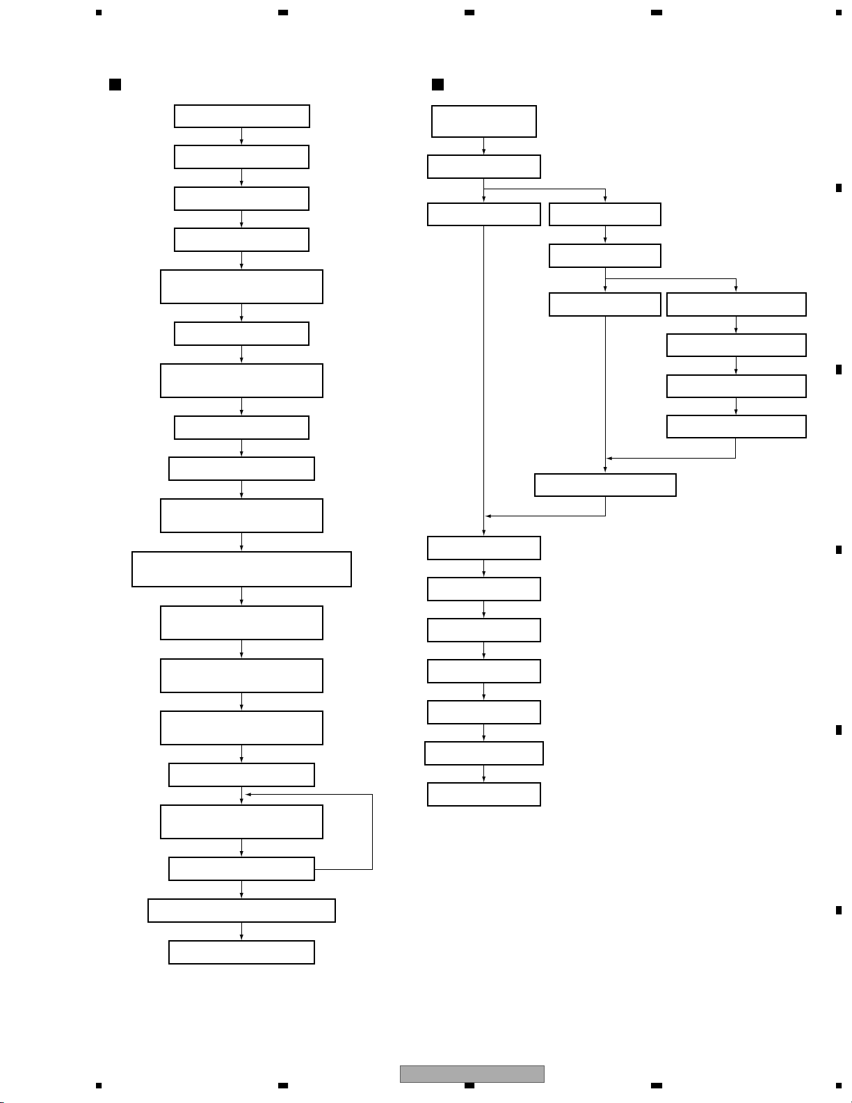
5678
Power ON
Register set of CPU
I/O port setting of CPU
Timer setting
A/D setting
Microcomputer inside RAM
initialization (zero clear)
FIP controller setting
Output mute set (the same
from power ON)
IC reset set
Analog SW initial setting
Main Start
Loop timer clear
(10 msec)
Check during mute
(during mute)
A
(mute completion)
RAM clear check
B
(during RAM clear) (RAM clear completion)
Effect CH select check
Effect mode select
Effect mode processing
C
Level meter processing
Wait for voltage stability
50 msec
Test mode check :
Route diverges to the normal and test
DSP software 1 transfer :
DSP initial setting
5 msec wait
DSP software 2 transfer :
Filter initial setting
5 msec wait
DSP software 3 transfer :
RAM initial setting
1000 msec wait
Wait for DRAM clear
DSP software 4 transfer :
Sharing program transfer
7 seg initial setting
Various effect & RAM initializing
Key check
SW check
Fader start control
Display control
Timer control
DSP data reception
Return to Main
D
E
Mute OFF timer set
1000 msec
∗ Mute time is 2000 msec in total.
DJM-3000
56
F
7
8
97
Page 98
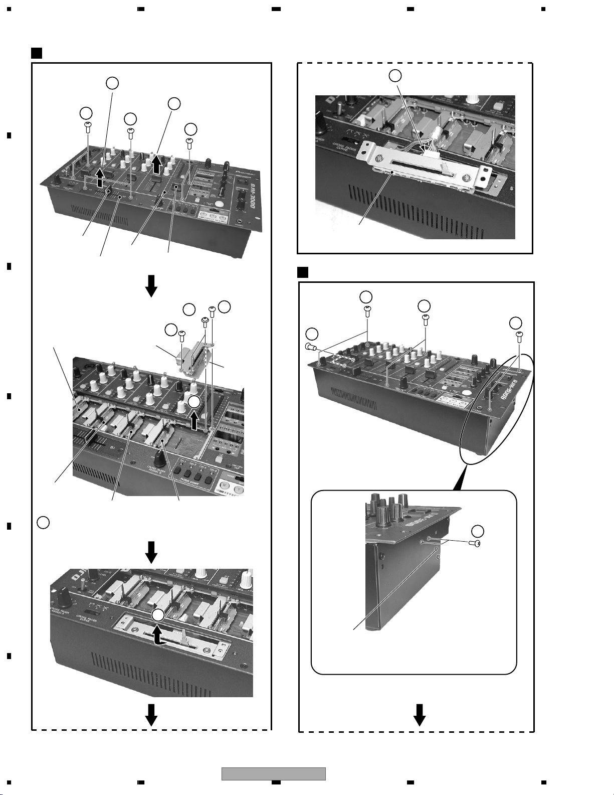
1234
7.1.1 DISASSEMBLY
Fader VR Section
A
1
×2
B
CROSS FADER
Knob
Slider Panel
C
CHF1 Assy
CROSS FADER Knob
4
Slider Panel
3
×2
Sub Panel
FADER Knob
5
Fader Bracket
FADER Knob ×5
2
Sub Panel
1
×2
6
×2
Disconnect a connector (CN336).
10
CF Assy
×5
Control Panel Section
×2
5
1
×2
2
×2
1
×2
1
MAF Assy
7
D
CHF2 Assy
CHF3 Assy
Remove other Fader VR Assys (CHF1 to CHF4 Assys) as
8
same as steps 5 to 7.
E
CHF4 Assy
×2
2
9
Caution:
These one screws are for the power switch section.
Do not remove two screws because the power supply
may short circuit.
F
98
1234
DJM-3000
Page 99

5678
TERMA and TERMB Assys
6
Tear off a adhesive tape.
4
CN305
5
Remove the Control Panel section.
• Rear Panel side
CN371
A
1
3
2
Screw
Nut
2
Washer ×4
×4
Screw ×4
2
Washer ×4
7
VR Assy
MIC Assy
DSP Assy
8
PCB Sheet VR Assy
POWER Assy
TRANS
Assy
7
3
6
REG Assy
5
3
B
7
C
PCB Support
×3
10
CN305
9
CN371
HP
Assy
PSW Assy
4
Cutting Pliers, etc.
VR Assy
7
PCB Sheet Rear
D
TERMB
Assy
TERMA
Assy
EFFECT
Assy
Diagnosis
56
DJM-3000
TERMB Assy
8
TERMB Assy
Wire Saddle Clip
Diagnosis
7
E
TERMA Assy
F
99
8
Page 100
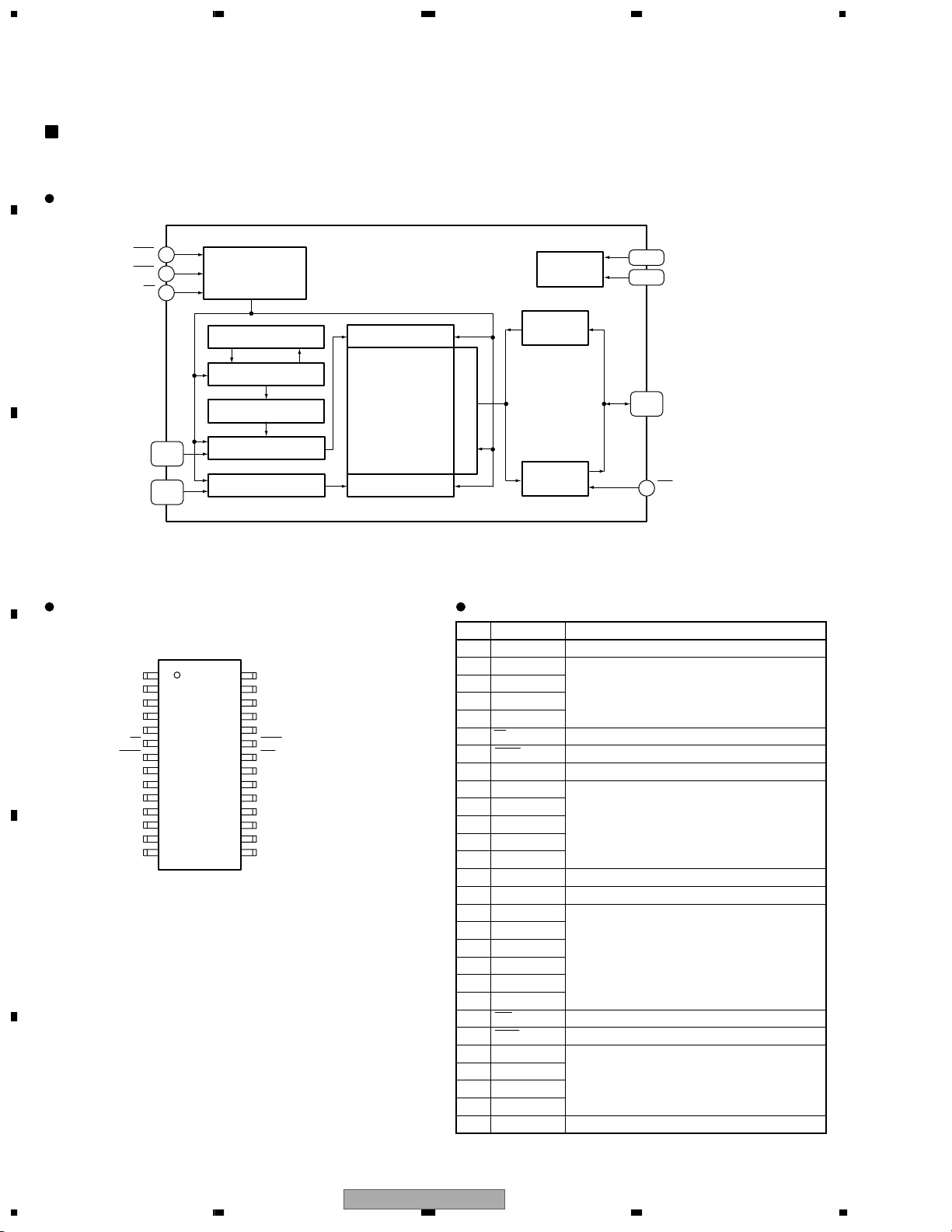
1234
7.2 PARTS
7.2.1 IC
• The information shown in the list is basic information and may not correspond exactly to that shown in the schematic diagrams.
A
K4F160812D-FC60 (DSP ASSY: IC113)
• CMOS DRAM
Block Diagram
RAS
CAS
7
23
6
W
Control
Clocks
VBB
Generator
B
Data In
Refresh Timer
Row Decoder
Buffer
Refresh Control
Memory Array
2,0970,152×8
Cells
Sense Amps & I/O
A0 to A10
9-13,
16-21
Refresh Counter
Row Address Buffer
Data Out
A0 to A8
10-13,
16-20
Col. Address Buffer Column Decoder
Buffer
C
1,14
15,28
2-5,
24-27
22
OE
Vcc
Vss
DQ0 to DQ7
Pin Arrangement (Top View) Pin Function
No. Pin Name Pin Function
1 Vcc Power supply (+3.3V)
Vcc 1
DQ0 2
D
DQ1 3
DQ2 4
DQ3 5
W6
RAS 7
N.C 8
A10 9
A0 10
A1 11
A2 12
A3 13
Vcc
Vss
28
DQ7
27
DQ6
26
DQ5
25
DQ4
24
CAS
23
OE
22
A9
21
A8
20
A7
19
A6
18
A5
17
A4
16
Vss14
15
E
F
2 DQ0
3 DQ1
4 DQ2
Data In/Out
5 DQ3
6 W Read/Write input
7 RAS Row address Strobe
8 N.C No connection
9 A10
10 A0
11 A1
Address inputs
12 A2
13 A3
14 Vcc Power supply (+3.3V)
15 Vss Ground
16 A4
17 A5
18 A6
19 A7
Address input
20 A8
21 A9
22 OE Data output enable
23 CAS Column address strobe
24 DQ4
25 DQ5
26 DQ6
Data In/Out
27 DQ7
28 Vss Ground
100
1234
DJM-3000
 Loading...