

LG DGS2028EKD, DGS2038EKD, DGS1858EKD, DGS1818EKD, DES2038EKD Service Manual
...
U.S.A Website: http://us.lgservice.com
Canadian Website: http://lg.ca
ELECTRIC & GAS DRYER
SERVICE MANUAL
CAUTION
READ THIS MANUAL CAREFULLY IN ORDER TO
PROPERLY DIAGNOSE PROBLEMS AND TO SAFELY
PROVIDE QUALITY SERVICE ON THESE DRYERS.
DGS2028EKD DGS2038EKD DGS1828EKD DGS1838EKD
DGS1858EKD DGS1818EKD DES2038EKD
DLE1101W DLG1102W
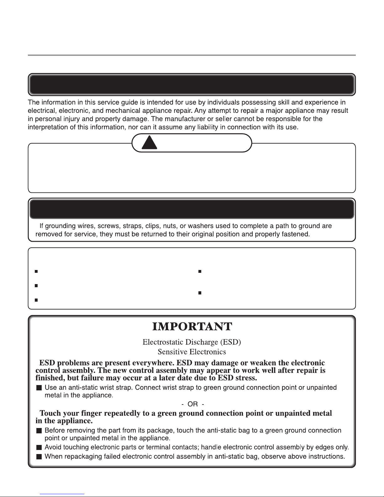
IMPORTANT SAFETY NOTICE
WARNING !
!
To avoid personal injury, disconnect power before servicing this product. If electrical power is required
for diagnosis or test purposes, disconnect the power immediately after performing the necessary checks.
To reduce the risk of personal injury, adhere to all industry recommended safety procedures including the
use of long sleeved gloves and safety glasses. Failure to follow all of the safety warnings in this manual
could result in property damage, injury to persons or death.
RECONNECT ALL GROUNDING DEVICES
WHAT TO DO IF YOU SMELL GAS:
Do not try to light a match, or cigarette, or turn on
any gas or electrical appliance.
Do not touch any electrical switches. Do not use
any phone in your building.
Clear the room, building or area of all occupants.
Immediately call your gas supplier from a
neighbor’s phone. Follow the gas supplier’s
instructions carefully.
If you cannot reach your gas supplier, call the fire
department.
2

CONTENTS
1. SPECIFICATIONS ............................................................................................................... 4
2. FEATURES AND BENEFITS .................................................................................................. 6
3. INSTALLATION INSTRUCTIONS .......................................................................................... 6
4. DRYER CYCLE PROCESS ..................................................................................................... 9
5. COMPONENT TESTING INFORMATION ............................................................................10
6. MOTOR DIAGRAM AND SCHEMATIC .............................................................................. 13
7. WIRING DIAGRAM .......................................................................................................... 14
8. FLOW SENSOR FUNCTION ............................................................................................. 15
8-1. FLOW SENSOR ...................................................................................................... 15
8-2. INSTALLATION TEST ................................................................................................ 16
8-3. TROUBLESHOOTING FOR FLOW SENSOR DRYER ................................................... 18
9. DIAGNOSTIC TEST .......................................................................................................... 19
9-1. TEST 1 120V AC ELECTRICAL SUPPLY ..................................................................... 20
9-2. TEST 2 THERMISTOR TEST - MEASURE WITH POWER OFF ....................................... 21
9-3. TEST 3 MOTOR TEST .............................................................................................. 22
9-4. TEST 4 MOISTURE SENSOR ................................................................................... 23
9-5. TEST 5 DOOR SWITCH TEST .................................................................................. 24
9-6. TEST 6 HEATER SWITCH TEST - ELECTRIC TYPE ........................................................ 25
9-7. TEST 7 GAS VALVE TEST - GAS TYPE ...................................................................... 26
9-9. TEST 8 MOTOR ASSEMBLY, DC, PUMP .................................................................... 27
10. CHANGE GAS SETTING (NATURAL GAS, PROPANE GAS) ......................................... 28
11. DISASSEMBLY INSTRUCTIONS .................................................................................... 30
12. EXPLODED VIEW............................................................................................................ 37
12-1. CONTROL PANEL AND PLATE ASSEMBLY .............................................................. 37
12-2. CABINET AND DOOR ASSEMBLY .......................................................................... 38
12-3-1. DRUM AND MOTOR ASSEMBLY: ELECTRIC TYPE ................................................. 39
12-3-2. DRUM AND MOTOR ASSEMBLY: GAS TYPE ........................................................ 40
3
1
SPECIFICATIONS
Name: Electric and Gas Dryer
Power supply: Refer to the rating label on the dryer.
Size: 27” X 403/16” X 29” (inch)
Dryer capacity: IEC 7.3 cu.ft.
Weight: 125.5 (Ibs)
Specifications are subject to change by manufacturer.
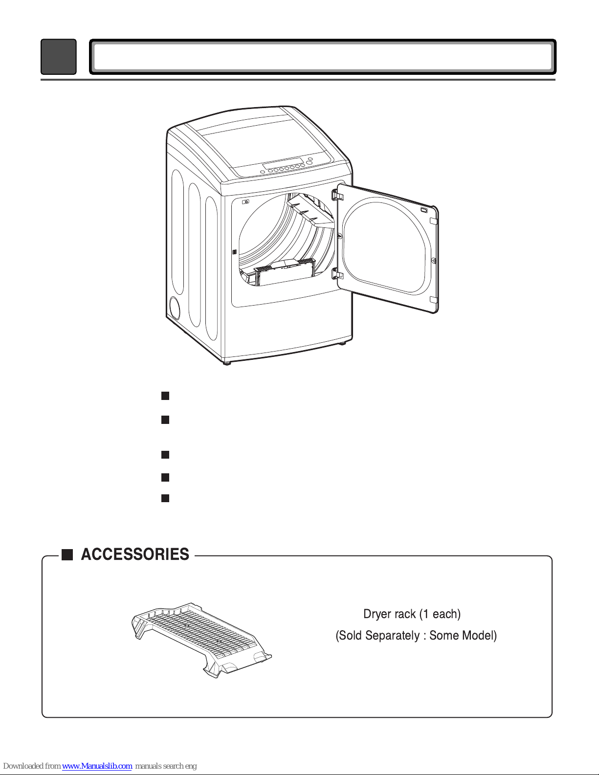
ACCESSORIES
Gas: 120 VAC Electric: 240VAC
Dryer rack (1 each)
(Sold Separately : Some Model)
See page 6 of this manual for usage instruction.
4
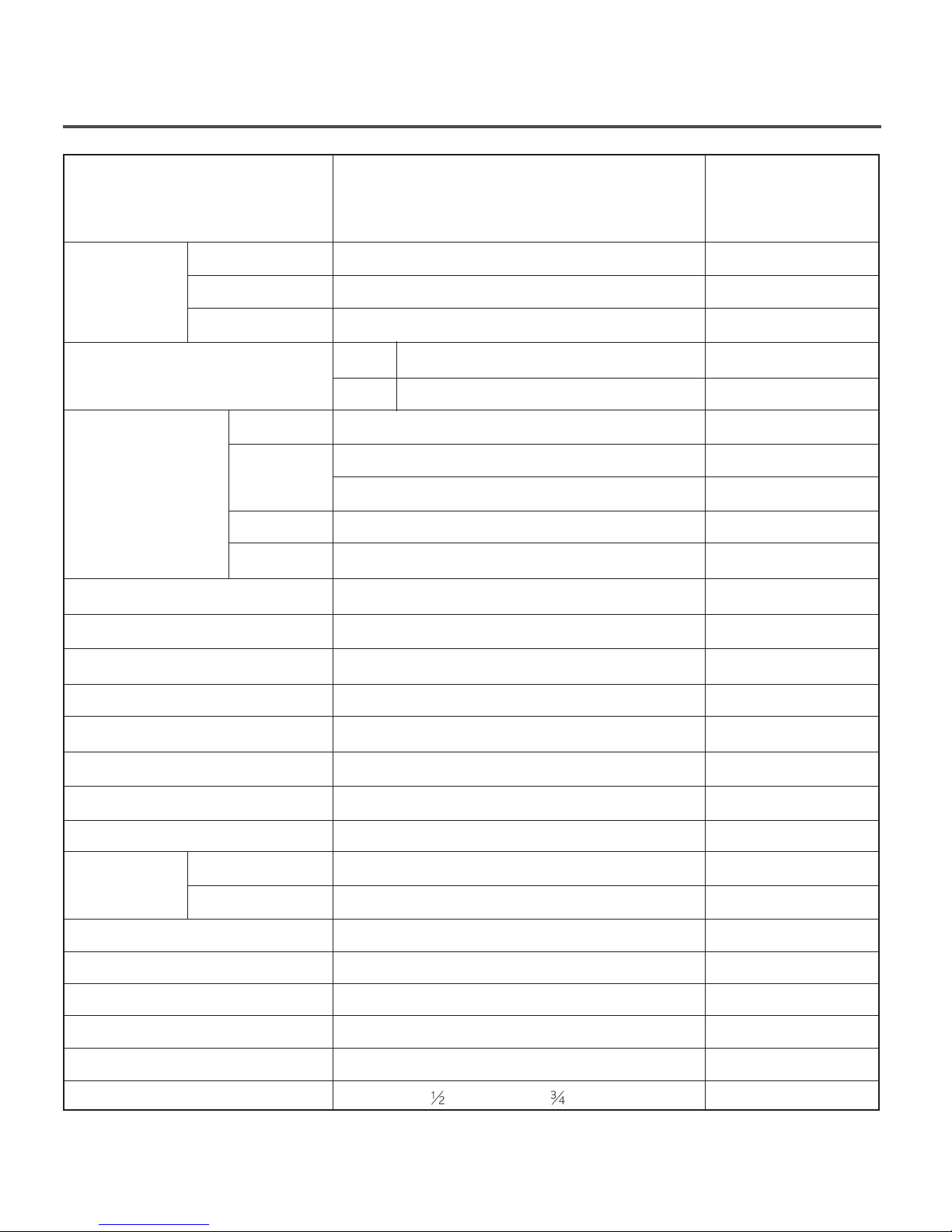
ITEM
DGS2028EKD DGS2038EKD
DGS1828EKD DGS1838EKD
DGS1858EKD DGS1818EKD
DES2038EKD
DLE1101W DLG1102W
REMARK
Material &
Finish
POWER
SUPPLY
ELECTRICITY
CONSUMPTION
CONTROL TYPE
DRUM CAPACITY
Weight (lbs) - Net
No. of Programs
Color
Top Plate
Door Trim
MOTOR
HEATER
LAMP
GAS VALVE
ELEC.
GAS
Blue White / Stainless Silver
White / Silver / Black
Chrome
120/240V 60Hz (26A)/120/208V 60Hz (23A)
120V/60Hz (11.5A)
250W (4.5A)
5400W (22.5A)
4100W (21A)
15 W (0.2A)
13 W (0.11A) x 2
Electronic
7.3 cu.ft.
124.9/144.4
9 / 12
AC 120V
AC 240V(ELECTRIC MODEL)
AC 208V(ELECTRIC MODEL)
AC 120V
AC 120V(GAS MODEL)
No. of Dry Options
No. of Temperature Controls
No. of Dry Levels
Sound levels
Moisture
Sensor
Temperature
Reversible Door
Drum
Child Lock
Interior Light
Product (WxHxD)
Packing (WxHxD)
27
”x 403/16”
29
1(on/off)
Available
Available
Available
Alcosta
Available
Available
”x 403”
5
6
4
5
x 29”(inch)
x 30
”
(inch)
Electrode sensor
Thermistor
2
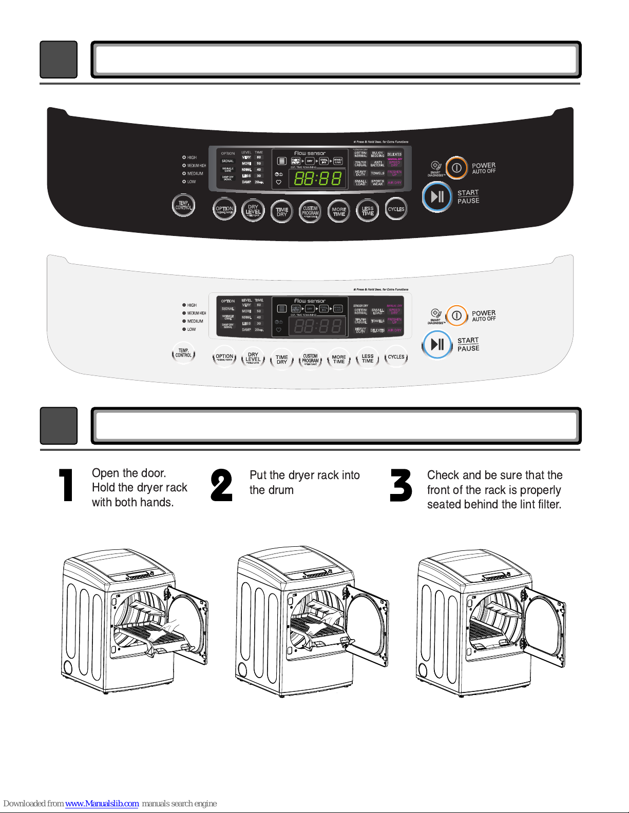
Open the door.
Hold the dryer rack
with both hands.
Put the dryer rack into
the drum
Check and be sure that the
front of the rack is properly
seated behind the lint filter.
FEATURES AND BENEFITS
3
INSTALLATION INSTRUCTIONS
6
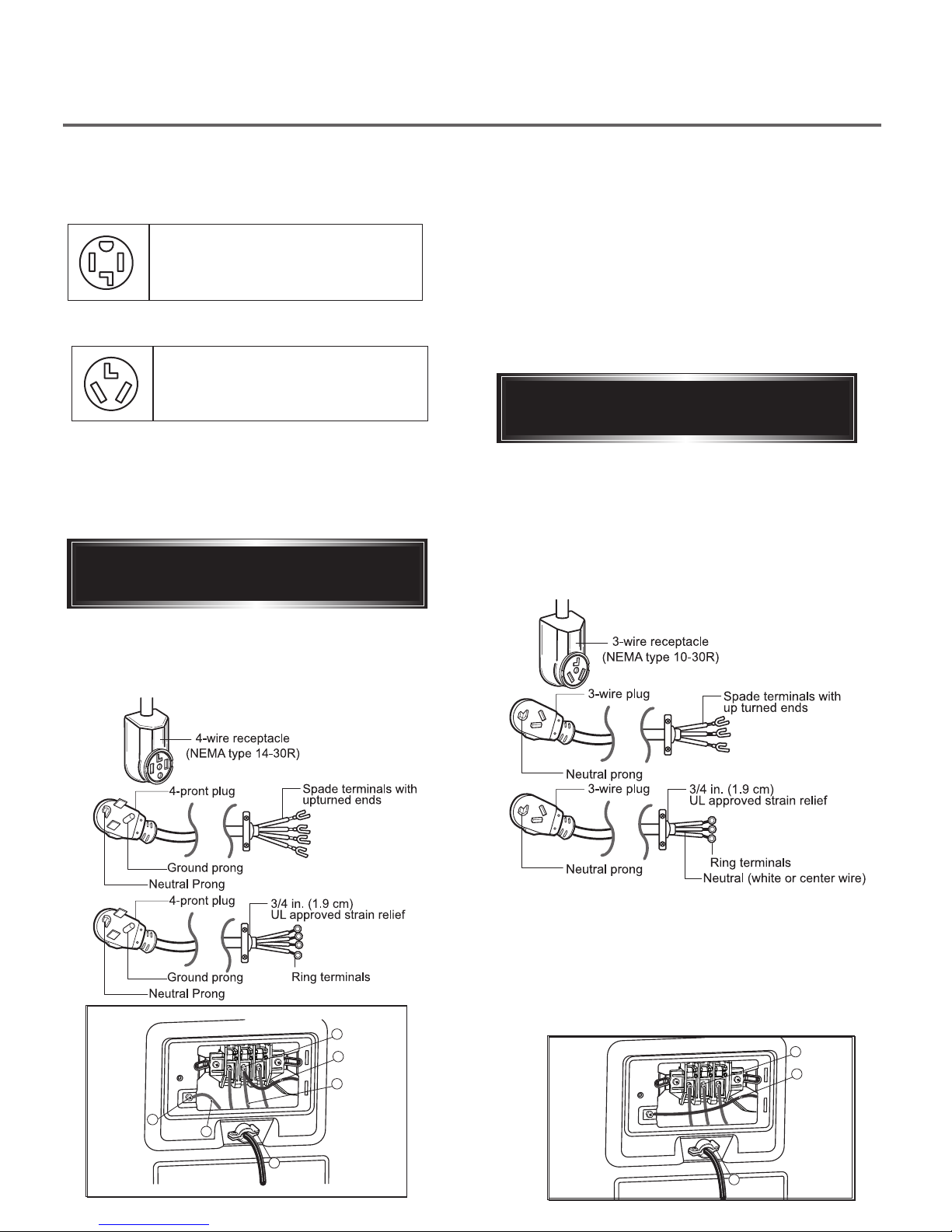
Review the following options to determine
the appropriate electrical connection for
your home:
4-wire receptacle
(NEMA type14-30R)
Use the instructions under option 1 if your home
homehas a 4-wire receptacle (NEMA type 14-30R).
3-wire receptacle
(NEMA type10-30R)
Use the instructions under option 2 or 3 if your
home has a 3-wire receptacle (NEMA type 10-30R).
Use option 2 if local codes and ordinances permit
the connection of a chassis ground to the neutral
connector. If this is not permitted, use option 3.
Option 1: 4-wire connection with
a Power supply cord.
1. Connect the neutral wire (white) of the power
cord to the center terminal block screw.
2. Connect the red and black wires to the left and
right terminal block screws.
3. Connect the ground wire (green) of the power
cord to the external ground screw. Remove the
neutral ground wire of appliance and connect it to
center screw.
4. Make sure that the strain relief screw is tightened
and that all terminal block nuts are tight and the
power cord is in the right position.
Option 2: 3-Wire Connection with
a Power Supply Cord
lf your local codes or ordinances permit the
connection of a frame-grounding conductor to the
neutral wire, use these instructions. If your local
codes or ordinances do not allow the connection of
a frame-grounding conductor to the neutral wire,
use the instructions under Section 3: Optional
3-wire connection.
• If your local codes or ordinances do not allow the
use of a 3 wire connection, or you are installing
your dryer in a mobile home, you must use a 4wire connection.
D
E
F
1. Connect the neutral (white or center) wire (B) to
the center, silver colored, screw (A) and tighten
securely.
2. Connect the other two power cord wires (red and
black) to the left and right terminal block screws
and tighten securely.
3. Tighten the strain relief screws (C) securely.
A
B
a
b
C
7
C
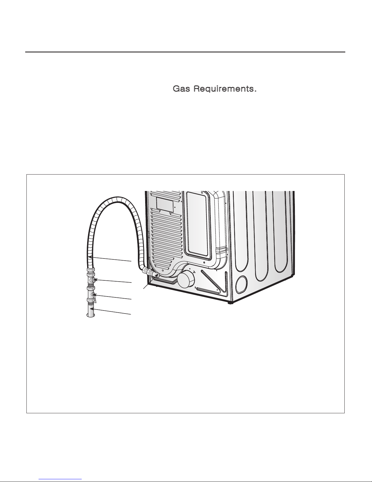
Connect Gas Supply Pipe (Gas Dryer ONLY)
For further assistance, refer to section on
Gas Requirements.
1. Make certain your dryer is equipped for use with the
type of gas in your laundry room. Dryer is equipped
3
at the factory for natural gas with a
/8” N.P.T. gas
connection.
2. Remove the shipping cap from the gas connection
at the rear of the dryer. Make sure you do not
damage the pipe thread when removing the cap.
1
3. Connect to gas supply pipe using a new flexible
stainless steel connector.
4. Tighten all connections securely. Turn on gas and
check all pipe connections (internal & external) for
gas leaks with a non-corrosive leak detection fluid.
5. For LP (Liquefied Petroleum) gas connection, refer
to section on Gas Requirements.
2
5
3
4
1 New Stainless Steel Flexible Connector
- Use only if allowed by local codes (Use
Design A.G.A. Certified Connector)
1
8
/
”NPT Pipe Plug (for checking inlet gas
2
pressure)
3 Equipment Shut-Off Valve
-Installed within 6’(1.8 m) of dryer
4 Black Iron Pipe
Shorter than 20’ (6.1 m) – Use ” pipe
Longer than 20’ (6.1 m) – Use ” pipe
3
8
5 ” NPT Gas Connection
/
8
3
8
/
1
2
/
4
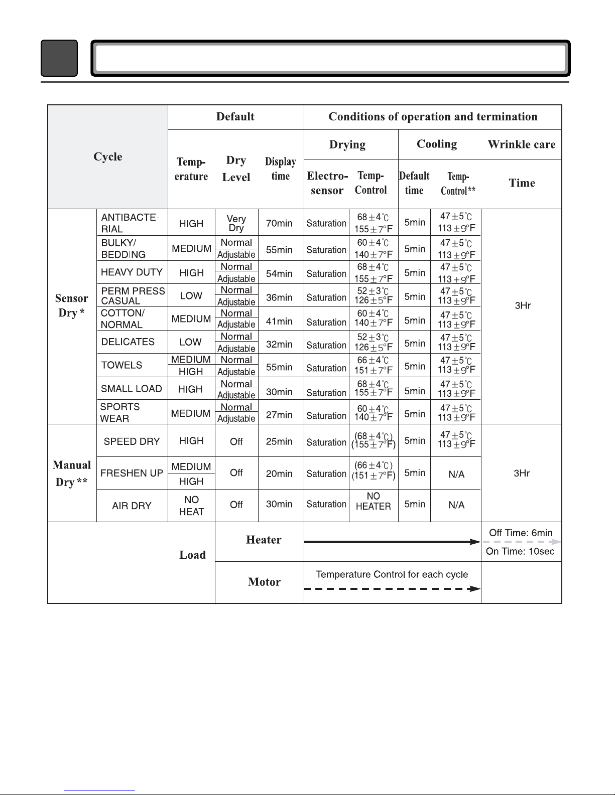
DRYER CYCLE PROCESS
* Sensor dry: Dry Level is set by users.
** Manual dry: Temperature control is set by users.
Default settings can be adjusted by users.
9
10
5
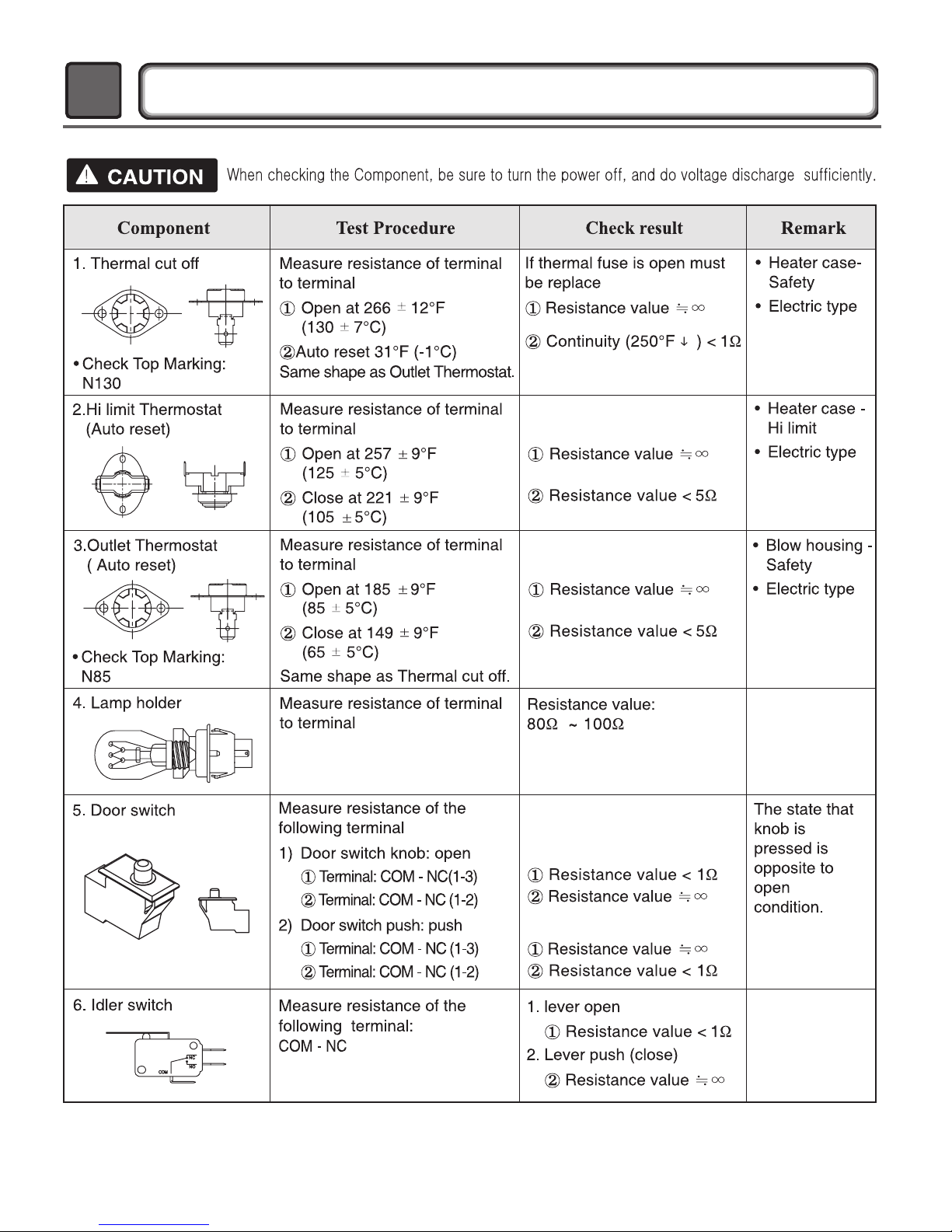
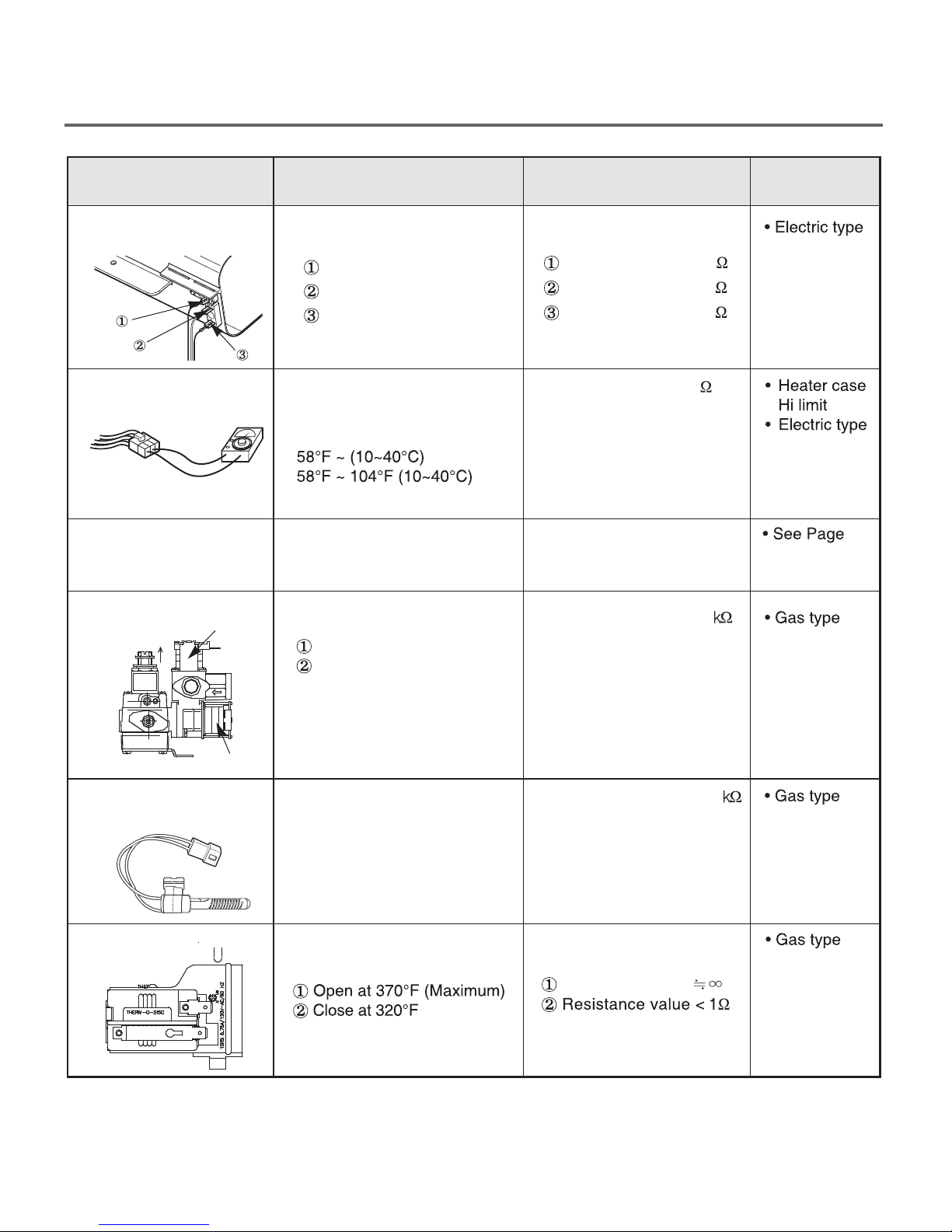
COMPONENT TESTING INFORMATION
5
Component Test Procedure
7. Heater
8. Thermistor
9. Motor
10. Gas valve
valve 1
Measure resistance of the
following terminal
Terminal: 1 (COM) - 2
Terminal: 1 (COM) - 3
Terminal: 2 - 3
Measure resistance of terminal
to terminal
Temperature condition:
Measure resistance of the
following terminal
Valve 1 terminal
Valve 2 terminal
Check result
Resistance value: 10
Resistance value: 10
Resistance value: 20
Resistance value: 10
Resistance value:1.5~2.5
Remark
13
11. Igniter
5318EL3001
12. Frame Detect
valve 2
Measure resistance from
terminal to terminal.
Measure resistance of termina
to terminal
11
Resistance value:100~800
Resistance value
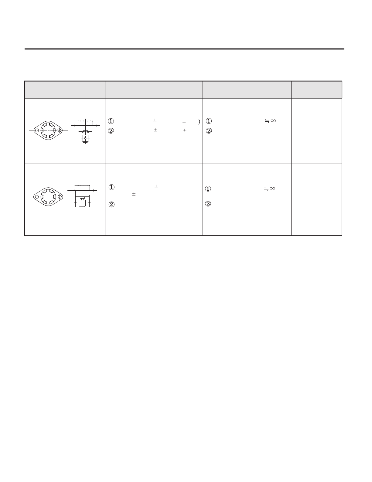
Component Test Procedure
Check result
Remark
13. Outlet Thermostat
(Auto reset)
• Check Top Marking:
N95
14. Outlet Thermostatt
(Manual reset)
• Check Top Marking:
N110
Measure resistance of terminal
to terminal
Open at 203
Close at 159 9°F (70 5°C)
Measure resistance of terminal
to terminal
Open at 212
(110
Manual reset
7°C)
7°F (95 5°C
12°F
Resistance value
Continuity < 1
If thermal fuse is open must
be replaced
Resistance value
Continuity < 1
Ω
Ω
• Gas type
• Gas funnel
• Gas type
• Gas funnel
12
 Loading...