

Page 1

Colour
Monitor
USER
BENUTZERHANDBUCH
MANUEL
GUIDA
GUIA
MODEL
GUIDE
D'UTILISATION
UTENTE
DEL
USUARIO
:
StudioWorks
7D
Page 2
FCC
Compliance
Statement
This
equipment
Class
are
equipment
cause
this
equipment
B
and
is
no
a
limits
interference
This
energy
may
there
installation.
If
reception
the
on),
one
user
or
more
-
Reorient
-
Increase
-
Connect
thattowhich
-
Consult
help.
Caution:
Electronics
to
operate
terminals,
be
attached
to
likely
resultininterference
has
been
tested
device
digital
pursuant
designedtoprovide
in
a
residential
installation.
generates,
if
not
installed
harmful
guarantee
does
(which
can
is
encouraged
of
the
or
relocate
the
separation
the
equipment
the
the
dealer
Changes
Inc.
for
the
equipment.
printers,
to
this
following
and
interference
that
interference
cause
be
determined
measures:
the
receiving
between
intoanoutlet
receiverisconnected.
or
an
or
modifications
compliance
Only
certified
etc.)
monitor.
Operation
to
and
found
to
Part
reasonable
and
radio
interference
by
to
correct
antenna.
the
not
void
can
will
turning
equipment
on
radio/TV
uses,
usedinaccordance
to
harmful
to
try
experienced
could
peripherals
to
comply
with
and
TV
radio
to
comply
15ofthe
FCC
protection
radiate
with
communications.
not
occur
to
the
the
interference
a
circuit
technician
expressly
the
user's
(digital
with
input/output
the
Class
non-certified
reception.
with
the
limits
Rules.
against
radio
the
These
harmful
frequency
instructions,
However,
in
a
particular
radioortelevision
equipment
and
the
different
approved
(or
your)
off
by
using
receiver.
from
for
by
authority
devices,
B
limits
peripherals
for
and
LG
may
is
shielded
Only
Canadian
This
Class
D.
Signal
O.
C.
B
digital
Interference-Causing
Cet
appareil
du
Reglement
numerique
sur
Cables
Notice
apparatus
Equipment
le
materiel
be
may
meets
delaclasse
brouilleur
used
with
all
requirements
Regulations.
B
respecte
du
Canada.
this
System.
toutes
of
the
les
Canadian
exigences
Page 3
Table
of
Contents
Introduction
Monitor
Registration
Important
Installation
Location
Control
On
Sound
General
Power
Image
Video
Panel
Screen
Selection
Management
Adjustment
Memory
Microphone
Audio
Features
Audio
Connections
Precautions
and
Function
Function
Display
Operation
Modes
Operation
(OSD)
and
Adjustment
System
of
Controls
Control
Adjustment
1
2
3
5
6
7
8
12
13
14
14
15
17
17
17
Low
Radiation
Self
Diagnostics
DDC
(Display
Troubleshooting
Service
Specifications
Warranty
Statement
Compliance
Data
Channel)
Tips
(MPR
II)
18
18
18
19
20
21
23
Page 4
Introduction
Thank
supports
high
operating
computers.
viewable)
environment,
see
easily.
The
microprocessor-based
to
you
different
For
greater
Swedish
For low
EPA
the
Power
Please
for
you
OSD,
resolution
modes.
The
is
excellent
where
The
adjustavarietyofimage
video
user
Nutek
cost
of
Energy
Management
review
purchasing
DDC1,
performance
It
is
17-inch
smaller
anti-glare
modes,
health
MPR
II
monitor
Star
Signalling
this
manual
a
Goldstar
DDC2B,
DDC2AB,
and
compatible
flat
Square
use
screen
treatment
On
in
Screen
for
controls,
including
and
7
pre-set
safety,
requirements
operation,
Requirements,
(DPMS)
completely
color
operation
with
a
Windows
sizes
is
easy
Display
this
for
low
this
monitor
and
protocol.
before
monitor.
and
Sound.
in
a
standard
Tube
result
on
design
or
in
the
PC
desktop
images
eyes.
(OSD)
automatically
modes.
monitor
radiation
utilizes
is
certified
complies
the
operating
This
will
It
variety
type
(15.7
controls
storing
emissions.
as
VESA
the
monitor
give
you
of
video
personal
inches
publishing
difficult
allow
to
35
up
with
the
meeting
Display
monitor.
to
1
Page 5
Monitor
The
model
These
You
should
as a
permanent
Registration
and
serial
numbers
are
record
record
numbers
unique
requested
of
your
are
to
this
information
purchase.
found
unit
on
and
here
Staple
not
the
available
and
your
rear
retain
receipt
of
this
unit.
to
others.
this
guide
here.
Date
of
Purchase
Dealer
Dealer
Dealer
Model
Serial
Notice
All
strictly
Trademark
Purchased
Address
Phone
No.
No.
rights
prohibited
reserved.
GoldStar
IBM
is
a
International
WARNING
expose
this
AVERTISSEMENT
Cela
peut
From
No.
Reproduction
without
Acknowledgments
isatrademark
registered
Business
:
To
trademark
reduce
appliance
:
Ne
entrainer
un
:
:
:
:
:
:
in
the
written
of
LG
Electronics
and
Machines
the
to
rainormoisture.
pas
incendie
Corporation.
riskoffireorelectric
placer
ou
manner,
any
permission
VGA
isatrademark
cet
appareil
une
decharge
in
whole
ofLGElectronics
Inc.
shock,
dans
un
endroit
electrique.
in
or
of
do
not
part,
Inc.
humide.
is
2
Page 6
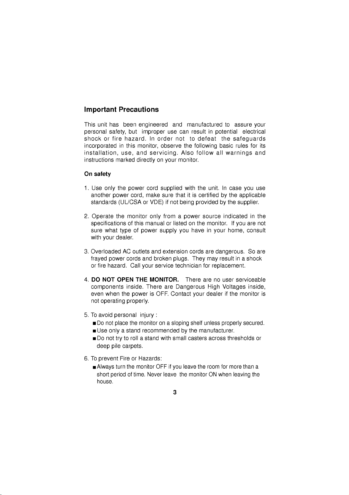
Important
This
unit
has
personal
shock
incorporated
installation,
instructions
On
or
safety
safety,
fire
Precautions
been
but
hazard.
in
this
and
use,
marked
engineered
improper
In
order
monitor,
servicing.
directly
on
use can
observe
your
and
not
monitor.
manufactured
result
to
the
following
Also
follow
defeat
in
potential
the
basic
all
to
assure
safeguards
rules
warnings
your
electrical
for
and
its
1.
Use
only
another
standards
2.
Operate
specifications
sure
what
with
your
3.
Overloaded
frayed
or
4.
power
fire
hazard.
DO
NOT
components
even
when
not
operating
5.Toavoid
Do
not
Use
only
Do
not
deep
pile
the
power
power
(UL/CSA
the
monitor
of
type
dealer.
AC
cords
OPEN
inside.
the
properly.
personal
place
a
stand
to
try
carpets.
cord
make
cord,
or
this
manual
of
power
outlets
and
Call
your
THE
There
power
injury
the
monitor
recommended
rollastand
supplied
sure
VDE)
only
supply
and
extension
broken
service
MONITOR.
is
OFF.
:
on
with
thatitis
if
not
from
a
or
listedonthe
plugs.
technician
are
Dangerous
Contact
a
sloping
small
with
being
power
you
There
by
the
unit.
certifiedbythe
provided
source
monitor.
in
have
cords
are
They
may
for
are
High Voltages
dealerifthe
your
shelf
unless
the
manufacturer.
casters
across
In
case
applicable
the
by
supplier.
indicated
If
you
home,
your
dangerous.
in
result
replacement.
no
user
serviceable
properly
thresholds
you
in
are
consult
So
a
shock
inside,
monitor
secured.
use
the
not
are
is
or
6.
To
prevent
Always
short
house.
FireorHazards:
turn
the
of
period
monitor
time.
Never
OFF
if
leave
you
3
the
leave
monitor
the
room
ON
for
when
more
leaving
than
a
the
Page 7
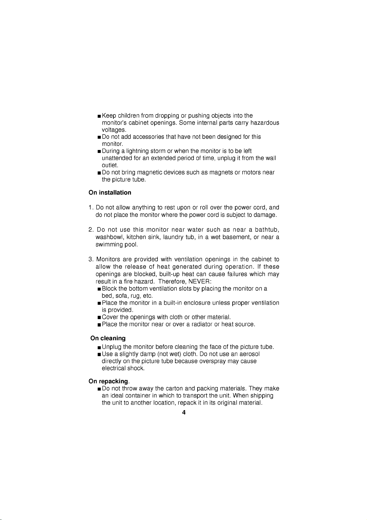
children
Keep
monitor's
voltages.
Do
not
monitor.
Duringalightning
unattended
outlet.
Do
not
the
picture
On
installation
1.
Do
not
allow
do
not
place
2.
Do
not
use
washbowl,
swimming
cabinet
add
accessories
foranextended
bring
magnetic
tube.
anything
the
this
kitchen
pool.
from
droppingorpushing
openings.
that
storm
or
devices
to
rest
monitor
monitor
sink,
where
near
laundry
Some
have
when
period
upon
the
the
such
power
water
tub,
internal
not
monitor
of
or
roll
in
been
time,
as
cord
such
a
objects
into
parts
designed
istobe
unplug
magnets
over
the
is
subjecttodamage.
as
near
wet
basement,
carry
it
or
power
the
hazardous
for this
left
from
motors
a
the
wall
near
cord,
bathtub,
or
near a
and
3.
Monitors
allow
openings
result
Block
bed,
Place
is
Cover
Place
On
cleaning
Unplug
Use
directly
electrical
On
repacking.
Do
an
the
are
the
release
are
in
a
fire
the
bottom
sofa,
rug,
the
monitor
provided.
the
openings
the
monitor
the
a
slightly
on
the
shock.
not
throw
ideal
container
unittoanother
provided
of
blocked,
hazard.
ventilation
etc.
monitor
damp
picture
away
with
heat
built-up
Therefore,
in
a
built-in
with
near
or
before
(not
tube
the
carton
in
which
location,
ventilation
generated
heat
can
NEVER:
slots
by
enclosure
clothorother
over
a
radiatororheat
cleaning
cloth.
wet)
because
and
to
packing
transport
repack
4
openings
during
cause
placing
unless
material.
the
faceofthe
Do
not
overspray
the
itinits
in
operation.
failures
the
monitor
proper
source.
use
an
may
materials.
unit.
When
original
the
cabinet
which
ventilation
picture
aerosol
cause
They
shipping
material.
on
If
tube.
to
these
may
a
make
Page 8
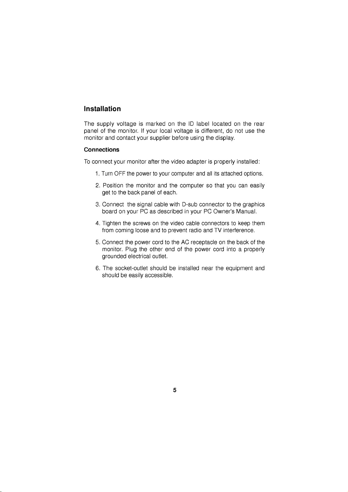
Installation
The
supply
of
panel
monitor
Connections
To
connect
1.
Turn
2.
Position
get
3.
Connect
board
4.
Tighten
from
5.
Connect
monitor.
grounded
6.
The
should
voltage
the
monitor.
and
contact
your
OFF
to
the
on
coming
socket-outlet
monitor
the
the
back
the
your
the
the
Plug
electrical
be
easily
is
marked
If
your
your
supplier
after
powertoyour
monitor
panel
cable
signal
PC
as
screws on
loose
and
cordtothe
power
the
other
outlet.
should
accessible.
on
local
the
video
and
the
of
each.
with
described
the
video
to
prevent
end
be
ID
the
voltage
before
label
is
using
adapterisproperly
computer
and
computer
D-sub
connector
in
your
cable
radio
AC
receptacle
of
the
power
installed
located
different,
the
display.
all
its
attached
so
that
PC
Owner's
connectors
TV
and
on
cord
near
the
on
the
do
not
use
installed:
options.
can
you
to
the
graphics
Manual.
to
keep
interference.
the
backofthe
into
a
properly
equipment
rear
the
easily
them
and
5
Page 9

Location
View
Front
Headphone
Jack
Microphone
Jack
Rear
View
and
Control
Function
Function
Built-in
Microphone
Panel
of
Controls
Brightness
Contrast
Adjustment
Power
Power
(DPMS)
Indicator
Adjustment
Control
ON/OFF
Switch
Control
ID
Label
MIC.
AUDIO
OUT
IN
MIC
OUT
Audio
IN
AC
Power
Socket
D-Sub
Signal
Cable
6
Page 10

Control
OSD
Select
Panel
/Adjust
Sound
Function
Control
Sound
Menu
Mute
Power
Indicator
Power
MIC
Brightness
Contrast
Button
OSD
ON/OFF
Buttons
easily
icon
you
on
through
shows
immediate
description
Power
This
monitor
Indicator,
normal
Power
This
If
power
the
ON/OFF
button
is
display
Indicator
Indicator
monitor
off),
Contrast
Adjust
located
contrast.
Brightness
Used
thumbwheel
decrease
Enter
Use
Display
this
button
Enter
the
you
of
is
in
push
this
the
beneath
to
button
this
(OSD).
an
use
a
operation.
lights
is
control
adjust
the
button
Button
frontofthe
OSD
menu.
what
the
chosen
understanding
for
each
button
used
to
turn
stand-by
the
in
DPM
indicator
display
control
located
display
will
mode,
Power
up
green
(Energy
color
to
the
this
indicatortoincrease
the
brightness.
to
start/enter
If
there
show
the
monitor
As
control
of
button.
the
monitor
indicated
Button
when
Saving)
changes
contrast
brightness
beneath
is
no
Main
Menu.
allow
you
the
again
the
and
OSD
choose
will
controls.
ON
by
to
monitor
mode
to
amber.
desired.
of
this
exit
on
Increase
Decrease
to
you
return
controls,
do.
These
The
and
an
amber
operates
adjust
following
OFF.
the
monitor
the
pictures
In
color
normally.
(stand-by/suspend/
Move
the
thumbwheel
or
decrease
the
screen.
indicator
the
from
screen,
to
the
increase
On
One
the
selected
case
the
Move
image
give
is
Power
to
display
Screen
press
a
the
its
the
or
of
7
Page 11

Adjustment
Use
this
is
also
used
Sound
Mute
Used
to
On
Screen
Making
sound
:
MIC
adjustments
on).
Built-in
parameters
Display
Control
the
available
Control
buttons.
use
of
the
adjustments
Example;
:
Note
the
the
(Monitor
screen).Asingle
Main
Menu
highlighted.
buttons
for
:
To
adjust
select
Display
of
the
system,
A
controls.
and
Control
for
selecting
selecting
mute
the
sound
on
microphone.
(OSD)
to
the
monitor
using
quick
exampleisgiven
Following
and
selections
PC
should
press
as
below,
(highlighting)
levelofthe
menu.
(means
Control
sound
Adjustment
image
is
quick
the
only
this
you
be
ON,
ENTER
of
the
with
the
selected
size,
and
ENTER
can
with
first
an
OSD
off)
position,
easy
below
section
make
button
item
icontobe
itemtobe
and
mute
with
button
to
familiarize
isanoutline
using
an
image
will
H-position(
adjusted.
off
and
the
On
and
the
or
present
adjusted.
(means
operating
Screen
Adjustment
with
you
of
the
OSD.
prompt
with
you
It
on
)
ENT:
H
POSITION
OSD
U
SEL:
8
Page 12

On
You
item
Listed
items
Screen
were
using
below
that
Display(OSD)
introduced
the
OSD
are
the
are
shown
to
the
system.
icons,
on
the
Selection
procedure
icon
names,
Menu.
and
of
and
Adjustment
selection
icon
descriptions
and
adjusting
of
an
the
Symbol
Horizontal
Position
Horizontal
Size
Vertical
Position
Vertical
Size
Side
Pincushion
OSD
To
To
To
To
To
move
adjust
move
adjust
correct
H
POSITION
50%
OSD
U
MAIN:
MAIN:
MAIN:
MAIN:
MAIN:
ADJ:
H
SIZE
50%
OSD
U
ADJ:
V
POSITION
50%
OSD
U
ADJ:
V
SIZE
50%
OSD
U
ADJ:
SPCC
50%
OSD
U
ADJ:
picture
Moves
Moves
image
Decreases
Increases
image
Moves
Moves
image
Decreases
Increases
the
Curves
Curves
Description
left
image
the
screen
the
screen
width.
the
sizeofthe
the
sizeofthe
and
down.
up
the
screen
the
screen
height.
the
sizeofthe
the
sizeofthe
in
bowing
the
the
and
image's
image's
and
image
image
image
image
edges
edges
out
left.
right.
screen
screen
up.
down.
screen
screen
of
right.
image.
image.
the
inwards.
outwards.
image.
image.
image.
Trapezoid
To
TRAPEZOID
50%
OSD
U
MAIN:
ADJ:
correct
Makes
the
Moves
geometric
the
top.
the
screen
screen
distortion.
image
wideratthe
image
narrower
at
top.
9
Page 13

Symbol
OSD
Description
Tilt
Zoom
Adjust
Mode
Recall
Degauss
Color
Select
MAIN:
MAIN:
MAIN:
MAIN:
ENT:
9300 7200
MAIN:
R
G
B
SEL:
To
TILT
50%
OSD
U
ADJ:
ZOOM
OUT:IN
OSD
U
ADJ:
RECALL
YES
:
OSD
U
ADJ:
RECALL
USER
MODE
OSD
U
ADJ:
DEGAUSS
OSD
U
ADJ:
COLOR
CODE
USER
OSD
U
ADJ:
correct
Tilts
Tilts
To
adjust
size
simultaneously.
Smaller
Bigger
If
the
monitor
mode,
preset
to
image
If
the
monitor
this
control
Used
to
move
select
demagnetize
accurate
K/
Decreases
a
To
7200
Horizontal
the
color
user.
image
the
screen
the
screen
the
the
is
this
factory
is
has
temperature,
rotation.
image
image
and
image
size.
image
operating
control
preset
operating
no
effect.
the
image
the
amount
left.
right.
Vertical
size.
will
in
in
a
mode.
a
image
factory
reset
user
picturetogive
and
color.
9300
of
colorinthe
the
mode,
K/
image.
COLOR
ADJ
50%
50%
50%
ADJ:
Increases
image.
the
amount
of
colorinthe
OSD
OSD
Adjust
To
CONTROL
H
POSITION:
V
POSITION:
OSD
U
MAIN:
ADJ:
position
OSD
correct
Moves
Moves
and
OSD
the
the
image's
Vertical
horizontal
vertical
Horizontal
position.
position.
position.
10
Page 14

Symbol
OSD
Time
OSD
OSD
TIME
SECONDS
5103060
OSD
U
MAIN:
ADJ:
To
select
Description
OSD
display
time
(seconds).
Language
Select
Mode
Information
Exit
To
LANGUAGE
ENGLISH
DEUTSCH
ESPANOL
FRANCAIS
ITALIANO
OSD
U
MAIN:
SEL:
INFORMATION
U
ADJ:
OSD
ADJ:
choose
control
To
inform
data.
To
disappear
names
the
users
language
are
displayed.
of
preset
of
the
OSD
in
which
the
and
user
mode
on
the
screen.
11
Page 15

Sound
You
item
Listed
items
were
using
below
that
Selection
introduced
the
are
OSD
are
shown
and
system.
the
Adjustment
to
the
procedure
the
icon
main
icons,
on
(
names,
Menu.
of
and
)
selection
icon
and
adjusting
descriptions
an
of
the
Symbol
Volume
Treble
Bass
Balance
MIC
Mute
OSD
VOLUME
MAIN: ADJ:
TREBEL
MAIN:
BASS
MAIN:
BALANCE
MAIN:
MICROPHONE
OFF
ON
MAIN:
Description
Raises
or
lowers
audio
50%
Raises
or
or
balance
or
lowers
lowers
disables
50%
ADJ:
Raises
50%
ADJ:
Changes
0%
ADJ:
Enables
ADJ:
level.
treble
Bass
level.
of
left/right
microphone
level.
speaker
usage.
level.
12
Page 16

General
After
following
section
operate
1.
Turn
monitor's
2.
Turn
3.
After
power
check
manual.
4.While
icons
adjustment
Operation
on
control
the
monitor.
on
the
power
on
the
booting
LED
the
connections
looking
Main
you
the
layout
monitor
PC.
(the
on
at
Menu
prefer.
general
by
indicator
PC
the
monitor
the
image
and
installation
and
function,
pressing
will
power-up
and
on
press
directions
you
the
power
Green
light
sequence
should
the
be
trouble-shooting
the
screen,
the
or
are
ready
button
or
Amber.
and
illuminated
select
buttons
and
reviewing
to
power-up
once.
The
initialization)
Green.
the
section
image
for
the
of
control
image
the
and
the
If
not,
this
13
Page 17

Power
This
during
(DPMS)
(VESA),
for
For
either
saving
indicatoronthe
When
power
If
the
monitor.Ifthe
again,
monitor
monitor
idle
reduced
the
a
states,
the
indicator
power
move
power
PC
is
Management
time,
guide
and
power
having
power
not
incorporates
following
linesofthe
is
certified
usage.
savings
and
front
indicator
power
your
in
feature
power
the
power
panel.
indicator
is
Amber,
is
indicatorisAmber
mouse
save
use,
System
new
the
Video
as
exceeding
saving
saving
is
the
monitor
Amber,
pointer
energy
circuitry
Display
Electronics
to
operate,
circuitry.
green,
press
or
touch
by
for
Power
the
EPA's
the
The
operation
operation
in
is
a
power
the
power
and
a
keyboard
turning
lowering
Management
Standards
Energy
monitor
monitor
is
indicated
is
saving
button
wish
you
it
off.
must
has
normal.
button.
energy
Association
Star
be
three
by
When
mode.
to
turn
to
use
usage
Signalling
program
used
with
power-
the
power
the
on
the
the
PC
When
the
Image
This
control
horizontal
Adjustment
monitor
system
trapezoid,
to
of
any
the
adjustments
turn
off
the
NOTE:
in
640x480
this
image
image
your
between
each
More
the
event,
640x480
The
event
display
settings
of
the
on
has
for
position,
zoom,
the
above
monitor
only
you
video
you
you
you
a
640x480
specific
image
a
microprocessor-based
vertical
the
made.
turn
you
may
video
in
DOS
to
Now
settings
mode
image
modes
the
and
Your
it
adjust
and
settings
adjusting
Rotation,
items,
you
and
time
change
mode
need
may
desire.
madeinthe
image
memory
and
levels.
items:
position,
following
height
color
microprocessor
settings
on
need
to
the
800x600
before.
an
at
to
adjust
(for
800x600
the
image
some
again
modes
an
microprocessor
video
From
800x600
made
you
in
the
video
14
On
Sound,
When
will
will
be
later
the
example,
video
controls
mode,
now
mode,
in
memory
Screen
you
side
make
Display
Horizontal
pincushion
adjustments
automatically
maintained
time.
image
you
mode
will
having
on,
the
each
modes
settings
may
for
again
memorize
already
when
monitor
of
these
even
windows).
to
you
section.
(OSD)
width,
memorize
if
again
from
go
meet
the
stored
switch
will
recall
modes.
and
you
is
a
In
the
new
Page 18

To
1)
adjust
Press
the
an
adjust.
Press
item
either
will
2)
3)Toadjust
4)
Any
image
the
monitor's
NOTE
adjust
Video
This
detect
scanning
PC
1280x1024
For
modes
described
:
Most
an
item's
Memory
multi-synchronous
and
range
this
area,
convenience,
come
below.
OSD
image
the
show
the
other
adjustments
memory.
menus
level,
display
of
relates
at
a
non-interlaced
from
controls:
select
button
or
item
controls,
will
the
Modes
several
30-65KHz
to
the
monitor
the
factory
or
(
button
to
adjust
level
and
effect
you
above
make
repeat
disappear
item's
OSD
auto-scanning
video
modes
Horizontal
a
maximum
refresh
hasa35
preset
)tohighlight
the
image.Adisplay
of
pushing
steps
will
be
after
5or6
must
stillbeshown
monitor
falling
and
50-110Hz
flicker-free
rate
of
60Hz
mode
to
popular
and
1)
stored
seconds.
within
usable
memory,
an
item
you
the
or
2).
automatically
In
on-screen.
can
automatically
the
Vertical.Inthe
resolution
Vertical.
of
video
modes
wish
for
that
keys.
order
monitor's
which
to
in
to
of
7
as
Mode
Display
1
VGA2
2
VGA3
VESA
3
VESA
4
VESA
5
VESA
6
VESA
7
If
the
monitor
video
you
may
that
had
factory
blank
now
adjust
will
also
switches
personal
Mode
720x400
640x480
640x480
800x600
1024x768
1024x768
1280x1024
card,
have
not
presets,
(empty)
the
be
to
image
detects
will
it
made
been
memory
stored
the
settings
Modes15-35
recall
will
it
OSD
mode
present
Horizontal
Frequency
31.47
KHz
31.47
KHz
37.50
KHz
46.88
KHz
56.48
KHz
60.02
KHz
63.98
KHz
are
empty
one
of
the
that
mode
before.Ifthe
before
store
a
modes
controls
in
to
mode
that
the
will
alsoberecalled.
Vertical
Frequency
and
new
(in
your
15.
monitor
70
Hz
60
Hz
75
Hz
75
Hz
70
Hz
75
Hz
60
Hz
can
accept
above
and
any
monitor
or
is
mode
this
example,
preference,
Whenever
15
Polarity
Horiz
sync
Verti
-
-
-
+
-
+
+
new
video
signals
from
stored
detects
not
one
automatically
mode
these
your
recognizes
sync
+
-
-
+
-
+
+
data.
image
a
new
of
the
video
as
Comments
Factory
may
user's
by
your
computer's
adjustments
video
above
in
one
When
15).
image
card
mode
fixed,
be
updated
setting.
mode
listed
of
settings
or
15,
your
but
the
you
PC
Page 19

A
note
about
There
isatotalof35
will
you
factory
factory,
modes
have
use
fixed
but
are
more
other7soft
modes
and add
If
that
factory,
1)
you
do
As
are
the
use
not
here's
the
control
available
encountered).
If
2)
you
monitor
datainmode
In
addition,
dataofmode
with
update
12345678910111213141516
m1m2m3m4m5m6m7m8m9m10m11m12m13m14m15m16
the
video
at
any
modes
be
may
left
blank
new
video
preset
encountered,
new
mode.
a
video
card
correspond
will
what
monitor
the
icons,
empty
have
used
encounters
15
If
the
16isdeleted
above
method,
from
mode
Example:All
memory
video
one
time.
that
cannot
overwritten
(empty).
modes,
modes
the
that
to
happen:
encounters
monitor
mode
modes
up
another
and
the
monitor
when
15tomode
35
modes
modes:
memory
Of
these
be
changed,
to
make
If
you
the
monitor
for
the
new
monitor
hasanumber
of
will
the
new
save
any
(mode
15-35
mode
old
dataofmode
encounters
and
this
monitor
35
are
modes,
generally
35
modes,
and
more
room.
use
will
the21blank
up
will
mode
delete
of
resolutions
store
storage.
the
monitor video
video
data,
the
new
15ifthisisthe
21
with
(36th
new
mode),
15isdeleted.
37th
new
data
encounters
will
37th
sequentially
filled
with
following
more
7
another
The
information
If
lowest
modes
if
you
adjust
information
video
will
it
video
replace
new
and
continuously.
333435
m33
modes
are
permanent,
7
are
remaining
modes
additional
memory
and
frequencies
in
first
modes,
store
data,
the
mode,
data
m34
m35
set
set
the
new
mode
and
the
and
the
the
than
at
in
new
mode
at
image
next
data
new
it
can
mode
data
the
21
still
the
the
the
old
16,
Because
most
available
the
with
fixed
new
fixed
monitor
28
video
your
Factory
When
12345678910111213141516
m1m2m3m4m5m6m7m8m9m10m11m12m13m14m15m16
Factory
recent
Soft
presets
dataisencountered
"m15"old
is
designed
own
modes
image
generated
settings
mode15deleted
this
way,
16
recalled
333435
m33
m34
will
you
by
always
your
automatically.
m35
have
graphics
the
card
Page 20

Microphone
On
the
left
microphone
reach
the
use
a
cable
and
into
the
Operation
side
there
is
in
PC's
here,
sound
it
may
card.Inorder
(supplied)toplug
MIC
input
jack
a
MIC
reduce
of
(Microphone)
the
long
to
use
into
the
rear
sound
your
jack.Byplugging
of
length
this
of
card
the
cable
MIC
jack,
monitor
(if
available).
needed
you
(MIC
a
need
OUT)
to
to
Audio
A
Features
major
featureofthis
conveniently
taking
up
any
can
you
attaching
result
Audio
Use
andtothe
left
the
easily
your
in
significantly
Connections
the
supplied
sound
and
right
PC
to
turn
monitor
a
space.
sound
less
in
signals
volume
stereo
to
audio
cabling
your
integrates
more
upgrade
PC
with
cabletoattachtothe
card
channel
the
up
is
audio
Because
capable
cardtothe
PC
in
one
of
the
its
built-in
and
(line
wire.
sound
amplifier
the
monitor
multimedia
back
space
rear
out).
Make
audio
system.
and
speakers
is
designed
of
this
requirements.
of
the
monitor
The
cable
sure
card
all
the
This
without
like
applications
monitor.
It
(AUDIO
will
carry
when
way.
you
use
this,
by
will
IN)
both
17
Page 21

Low
Radiation
This
monitor
low
radiation
static
screen
agency
Extremely
in
Sweden,
Low
meets
emissions,
electromagnetic
Self
Diagnostics
This
monitor
and
informs
Diagnostics
is
detected.
lighted,
can
you
OSD.
In
alerting
Compliance
one
coating.
Frequency
range.
sense
of
This
this
case
to
you
of
offering
These
limit
this
OSD
check
the
the
(ELF)
when
condition
the
message
the
(MPR
strictest
the
user
guidelines,
amount
and
there
is
by
may
pop
up
CHECK
cable connections.
signal
II)
guidelines
extra
shielding
set
forth
of
emission
Low
Very
a
possible
presenting
when
S/CABLE
available
by
Frequency
problem
you
it
is
On
and
a
government
allowed
with
but
will
today
an
anti-
in
(VLF)
present,
a
Self
no
signal
be
high
for
the
DDC
(Display
DDC
isacommunication
automatically
monitor
DDC1
the
datatothe
DDC2AB
example,
screen
NOTE:
has
and
DDC2B
PC
and
monitor
has
the
with
PC
must
informs
three
the
the
Data
monitor.
the
PC
PC
support
Channel)
the
DDC
carry
but
not
function
can
fetch
keyboard.
host
function;
out
Under
commands
of
screen
DDC
channel
system
(PC)
DDC1,
uni-directional
these
situations,
to
bi-directional
data from
functions
to
18
over
about
DDC2B,
communication
control
monitor
do
this.
which
the
the
communication.
the
its
capabilities.This
and
PC
sends
monitor
and
monitor
DDC2AB.
between
display
settings.
adjust
For
the
Page 22

Troubleshooting
Symptom:
Possible
The
signal
Symptom:
Possible
Display
These
The
signal
Check
The
frequency
the
monitor.
The
signal
Signal
Symptom:
or
not
a
Possible
current
the
image
Self
causes:
cable
The
causes:
power
is
no
cable
the
computer
cable
connector
The
rectangle
Causes:
operating
to
your
diagnostics
is
not
power
management
sync
signal.
is
not
of
the
HORZ:
VERT:
is
incorrectly
pin
assignment
image
shape.
Image
mode.
liking.
message.
connected.
LED
is
fastened
power
sync
input
30KHz-65KHz
50Hz-110Hz
on
the
adjustment
Use
the
illuminated
mode.
securely.
and
graphics
is
outside
configured
on
page
SCREEN
SELECT
orange
adapter
21
is
not
not
and
the
operating
or
connected.
for
reference.
centered,
been
or
blinking
configuration.
range
or
too
done
yet
or
buttons
orange.
Refer
small,
in
to
of
to
the
set
Symptom:The
(blinking
Possible
standard.
VESA
orange
DPMS
monitor
LED).
Causes:Computer
Either
the
PC
power
management
doesn't
or
the
enter
video
video
function.
19
the
signal
controller
power
is
card
saving
not
is
VESA
not
off
DPMS
using
mode
the
Page 23

Service
1.
Unplug
qualified
the
service
The
power
has
Liquid
The
monitor
The
monitor
instructions.
operating
result
may
qualified
The
monitor
damaged.
The
monitor
Snapping
while
the
make
occasional
changing
2.
Do
not
attempt
removing
hazards.
3.
When
replacement
verifyinwriting
characteristics
replacements
monitor
personnel
cord
or
been
spilled
has
does
Adjust
instructions.
in
damage
technician
has
exhibitsadistinct
or
popping
monitor
video
modes.
to
covers
Refer
may
all
servicingtoqualified
that
as
the
can
prevent
from
the
when
plugisdamaged
into
the
been
exposed
not
operate
those
only
An
improper
and
often
to
restore
been
dropped
from
the
is
operating.
sounds
service
parts
when
expose
are
the
replacements
the
required,
original
fire,
wall
outlet
:
monitor.
to
rain
normally
controls
or
frayed.
or
and
water.
following
that
are
refer
adjustment
requires
the
monitor
or
the
extensive
to
cabinet
normal
has
changeinperformance.
monitoriscontinuous
Itisnormal
being
monitor
you
parts.
shock,
to
Use
for
some
turned
on
yourself,asopening
dangerous
service
have
used have
and
the
of
manufacturer
other
personnel.
service
hazards.
the
covered
of
other
work
been
monitors
or
off,
voltage
the
servicing
operating
in
the
controls
a
by
operation.
or
frequent
or
when
or
other
technician
same
safety
specified
to
to
or
4.
Upon
completion
service technician
manufacturer's
5.
When
a
video
disposal
service
could
technician
of
service
monitor
result
to
any
to
perform
manual.
reaches
in
dispose
service
a
picture
or
repairs
the
safety
the
end
tube
of
the
monitor.
20
to
the
check
of
its
useful
implosion.
monitor,
described
life,
Ask
ask
in
improper
a
qualified
the
the
Page 24

Specifications
Sync
signal
Type
types
Green
video
H.
sync
V.sync
separate
(N.C
DPM
MODE
Normal
Stand-by
Suspend
Off
Signal
sync
:
no
connection)
(Display
connector
1
6
10
11
15
Power
H.sync
On
Off
On
Off
5
Video
Management)
V.sync
pin
assignment
On
On
Off
Off
Pin
10
11
12
13
14
15
1
2
3
4
5
6
7
8
9NC
H.
Video
On
Off
Off
Off
Separate
Red
Green
Blue
Ground
Self-Test
Red
Green
Blue
Ground
Ground
SDA
Horiz.Sync
Vert.Sync
SCL
sync
Power
Consumption
120W
15W
15W
Sync
Ground
Ground
Ground
V.
sync
LED
Color
Green
Amber
Amber
5W
Amber
21
Page 25

Specifications
Picture
17
Darkface,
Sync
Horizontal
Vertical
Input
Signal
Video
Display
Input
Resolution:1280
Audio
RMS
Input
Built-in
Power
Power
100-240VAC
tube
inch
(15.7
0.28
Input
Freq.
Form
input
Input
Area:
Form
Audio
Sensitivity
MIC:E.C.M
Consumption:
input
inches
Freq.
:
Separate,
:
15
:
Separate,
Output
50/60Hz
viewable)
mm
dot
pitch
:
30KHz
:
50Hz-110Hz
TTL,
D-Sub
pin
11.8"x8.9"/300x225mm
RGB
x
1024,
:
4
W
:
0.7
Vrms
type
120
2.0A
FST,
-
KHz
65
(Automatic)
(Automatic)
positive/negative
connector
Analog,
60Hz
(R+L)
Watts
Watts
Watts
Condenser
max
suspend
DPMS-Off
(Electret
15
5
Non-glare,90degree
0.7
Vp-p/75
ohm,
positive
Microphone)
mode,
stand-by
mode
deflection,
mode
Dimensions(WxHxD)
x
442
(
(42.9
x
436mm/18.3
net
)
lbs)
in
a
this
commitment
465
Weight
19.5
Information
not
represent
document
x
17.4x17.2
is
subject
on
the
part
inches
to
change
of
LG
22
without
Electronics
Inc.
notice
and
does
Page 26

LG
Electronics
to
be
defectiveinmaterial
the
date
of
original
the
during
MODEL
No
WARRANTIES,
LIMITED
U.S.A.,
INCONVENIENCE,
ARISING
BREACH
WARRANTY
Some
on
warranty
Therefore
To
To
Assistance:
For
Service
warranty
#
other
express
TO THE
INC.
OUT
statesdonot
how
longanimplied
gives
To
damagesorproblems
To
damagesorproblems
current
or
To
service
expaining
these
Prove
Warranty
Obtain
ProductorCustomer
Your
Nearest
Center:
ready.
All
Customers
Please
Call
U.S.A.,
SHALL
OF
ANY
OF
you
voltage.
calls,
the
operation
costs
In
Inc.
purchase.
periodaslong
LABOR
3
YEARS
warranty
INCLUDING
DURATION
NOT
LOSS
OF
THE
EXPRESS
MERCHANTABILITY
allow
specific
THE
which
are
CUSTOMER
Coverage:
Authorized
Canada
GOLDSTAR
LIMITED
will
or
USE
the
warranty
legal
ABOVE
which
which
do
of
paid
or
repair
workmanship
This
warranty
as
PARTS
3
YEARS
CRT
3
YEARS
is
applicable
THE
OF
BE
LIABLE
OR
ANY
OR
OF,
OR
exclusionorlimitationofincidental
lasts,
and
rights
WARRANTY
result
result
not
involve
the
unit.
the
consumer.
by
at
under
itisin
WARRANTY
IMPLIED
THE
OTHER
INABILITY
IMPLIED
so
you
from
from
defective
ASSISTANCE
its
to
APPLICABLE
WARRANTY
option
normal
is
good
the
U.S.
HOW
Call
please
ZIP
this
product.
EXPRESS
FOR
THE
DAMAGES,
these
limitationsorexclusions
also
may
delivery
misuse,
workmanship
Retain
of
Copy
time
warranty
Call
1-800-243-0000
Push
Appropriate
Call
1-800-243-0000,
have
your
(905)-670-0650
MONITOR
without
replace,
use,
during
to
only
including
PERIOD
SERVICE
1-800-243-0000,
have
your
code
ready.
THE
WARRANTY
WARRANTY
LOSS
TO
USE,
WARRANTY,
TO
have
other
DOES
or
improper
abuse,
accident,
Sales
your
Sales
your
service
product
type
charge,
the
the
original
Alaska,
IS
product
DURATION
OF
OF
THE
DIRECT
THIS
INCLUDING
THIS
PRODUCT.
or
consequential
rights
NOT
installation.
alteration,
or
material,
NUMBERS:
Receipt
Receipt
is
provided.
(Mon-Fri
Menu
Code.
24
hrs
(Monitor,
your
warranty
period
purchaser
Hawaii
HANDLED
24
hrs.
a
day,7days
(Monitor,
type
MERCHANTABILITY,
HEREIN.
USE
OF
OR
CONSEQUENTIAL,
PRODUCT
not
may
which
vary
APPLY:
or
suchashead
to
prove
must
be
submittedatthe
8am-5pm
a
day,7days
TV,
VCR)
product
and
U.S.
OF
ANY
LG
ELECTRONICS
THE
THE
damages
apply
from
incorrect
date
CST)
and
which
listed
below from
of
the
Territories
per
TV,
IMPLIED
PRODUCT,
OR
FOR
IMPLIED
or
to
statetostate.
electrical
cleaning
of
purchase.
week,
per
ZIP
proves
product
week,
VCR)
ANY
limitations
This
you.
and
please
code
and
IS
23
Page 27

COLOR
MONITOR
OWNER'S
Please
before
MODEL
P/NO:3828TUL003M
carefully
attempting
:
StudioWorks
read
to
this
operate
(S-9611)
MANUAL
manual
monitor.
your
7D
Page 28

Page 29

Page 30

 Loading...