

Page 1

Colour
Monitor
USER
BENUTZERHANDBUCH
MANUEL
GUIDA
GUIA
MODEL
GUIDE
D'UTILISATION
UTENTE
DEL
USUARIO
:
StudioWorks
74m
Page 2

Table
of
Contents
Introduction
Monitor
Important
Installation
Controls
General
Power
Image
Video
Audio
Audio
DDC
Management
Adjustment
Memory
Features
Connections
(Display
Registration
Precautions
Layout
and
Operation
Modes
Data
Descriptions
System
Channel)
1
2
3
5
6
8
9
9
10
12
12
12
Troubleshooting
Service
Input
Specifications
GoldStar
Monitor
Tips
Limited
Warranty
13
14
15
17
Page 3

Introduction
Thank
you
supports
resolution
modes.
The
17-inch
excellent
where
smaller
anti-glare
For
low
cost
EPA
the
Power
Please
Management
review
for
purchasing
DDC1,
performance
It
is
compatible
flat
for
use
screen
and
anti-static
of
monitor
Energy
this
DDC2B,
Square
in
a
windows
sizes
Star
Requirements,
Signalling
manual
a
Goldstar
DDC2AB
and
operation
with
standard
Tube
result
face
treatment
operation,
(DPMS)
completely
and
design
or
desktop
in
images
this
color
Sound.
in
a
variety
PC
type
(15.7
is
easy
monitor
and
utilizes
protocol.
before
monitor.
will
It
of
personal
inches
publishing
difficult
on
the
is
certified
to
the
operating
This
give
you
video
operating
computers.
viewable)
environment,
see
easily.
eyes.
as
VESA
the
monitor.
monitor
high
is
The
meeting
Display
1
Page 4

Monitor
The
model
These
You
should
as a
page.
Registration
and
numbers
record
permanent
serial
are
requested
record
numbers
unique
of
to
information
your
are
this
unit
purchase
found
and
here
staple
on
not
the
available
and
your
rear
retain
of
this
to
this
receipt
unit.
others.
guide
to
this
DateofPurchase
Dealer
Dealer
Dealer
Model
Serial
Notice
All
strictly
Trademark
GoldStar
IBM
International
Purchased
Address
Phone
No.
No.
rights
prohibited
is
reserved.
Acknowledgments
isatrademark
a
registered
WARNING
expose
this
appliance
No.
Business
:
To
From
Reproduction
without
reduce
the
trademark
Machines
to
rainormoisture.
:
:
:
:
:
:
in
any
of
written
LG
permission
Electronics
and
Corporation.
the
riskoffireorelectric
manner,
ofLGElectronics
Inc.
VGA
in
whole
or
isatrademark
shock,
in
part,
Inc.
do
is
of
not
AVERTISSEMENT
Cela
peut
entrainer
:
Ne
un
pas
incendie
placer
ou
cet
une
2
appareil
decharge
dans
un
electrique.
endroit
humide.
Page 5

Important
This
unit
has
personal
shock
incorporated
installation,
instructions
On
safety,
or
safety
Precautions
been
but
fire
hazard.
in
this
use
marked
engineered
improper
In
monitor,
and
servicing.
directly
order
observe
on
use
your
and
can
not
Also
monitor.
manufactured
result
to
defeat
the
following
follow
in
potential
basic
all
to
assure
the
safeguards
warnings
electrical
rules
for
your
its
and
1.
Use
another
only
the
power
standards(UL/CSA
2.
Operate
the
specifications
sure
what
dealer.
your
3.
Overloaded
4.
frayed
or
DO
fire
NOT
power
hazard.
OPEN
components
even
when
not
operating
5.Toavoid
deep
6.
To
Do
not
Use
Do
not
prevent
personal
place
only
try
pile
Always
short
period
the
house.
power
cord,
or
monitor
of
this
of
type
AC
inside.
the
outlets
cords
Call
THE
power
power
your
properly.
injury
the
monitor
a
stand
recommended
to
rollastand
carpets.
FireorHazards:
turn
the
monitor
of
time.
cord
make
VDE)
only
manual
and
and
MONITOR.
There
is
Never
supplied
sure
if
from
or
supply
extension
broken
service
are
Off.
:
on
with
Off
with
thatitis
not
being
a
power
listedonthe
have
you
plugs.
technician
There
Dangerous
Contact
a
sloping
by
small
if
leave
you
leave
the
the
unit.
certifiedbythe
provided
source
monitor.
in
your
cords
are
They
may
for
are
High
dealerIfthe
your
shelf
unless
the
manufacturer.
casters
the
monitor
across
room
In
case
applicable
the
by
home,
supplier.
indicated
If
you
consult
dangerous.
in
result
replacement.
no
user
serviceable
Voltages
monitor
properly
thresholds
for
more
On
when
you
in
are
So
a
shock
inside,
secured.
than
leaving
use
the
not
are
is
or
a
3
Page 6

children
Keep
cabinet
Do
not
monitor.
Duringalightning
foranextended
Do
not
the
picture
On
installation
1.
Do
not
allow
do
not
place
2.
Do
not
washbowl,
swimming
openings.
add
accessories
bring
tube.
anything
the
use
this
kitchen
pool.
from
droppingorpushing
Some
storm
or
of
period
monitor
sink,
devices
to
rest
where
laundry
magnetic
monitor
internal
that
have
when
time,
upon
the
near
parts
not
the
unplug
such
or
power
water
tub,
carry
been
monitor
it
from
as
roll
cord
such
in
a
objects
into
hazardous
designed
istobe
the
wall
magnets
over
wet
or
the
power
is
subjecttodamage.
as near
basement,
the
left
outlet.
motors
monitor's
voltages.
for
this
unattended
near
cord,
a
bathtub,
or
near
and
a
3.
Monitors
allow the
openings
result
bed,
Cover
On
cleaning
on
On
repacking.
an
the
in
a
Block
the
sofa,
Place
the
is
provided.
the
Place
the
Unplug
Use
a
slightly
the
picture
Do
not
ideal
unittoanother
are
release
are
fire
bottom
rug,
monitor
openings
monitor
the
monitor
throw
container
provided
of
blocked,
hazard.
ventilation
etc.
in
near
damp
tube
away
in
with
heat
generated
builtupheat
Therefore,
a
built-in
with
clothorother
or
before
(not
wet)
because
the
carton
which
location,
ventilation
NEVER:
slots
enclosure
over
a
radiatororheat
cleaning
cloth.
overspray
and
to
transport
repack
4
openings
during
can
by
placing
the
Do
may
packing
itinits
operation.
cause
failures
the
unless
material.
faceofthe
not
use an
cause
materials.
the
unit.
original
in
the
monitor
proper
source.
picture
aerosol
electrical
When
material.
cabinet
If
these
which
on
a
ventilation
tube.
directly
shock.
make
They
shipping
to
may
Page 7
Installation
The
supply
of
panel
monitor
Connections
To
connect
1.
Turn
2.
Position
get
3.
Connect
board
4.
Tighten
from
5.
Connect
monitor.
grounded
6.
The
should
*
Other
than
cable
Example:
change
supplied
voltage
the
monitor.
and
contact
your
OFF
to
the
on
coming
socket-outlet
Users:
on
the
or
adapter
from
cable
is
If
your
monitor
the
powertoyour
the
monitor
back
panel
the
signal
PC
your
the
screws
loose
the
power
the
Plug
electrical
be
cable
For
accessible.
easily
To
work
supplied,
blocktoattach the
MACII
the
high
to
a
standard
marked
your
supplier
after
local
the
on
voltage
before
video
computer
and
the
of
each.
cable
with
as
described
on
the
video
and
to
prevent
cordtothe
other
end
outlet.
should
with
be
equipment
you
users,
you
density(3row)
(2
row)
ID
the
label
is
using
different,
the
adapterisproperly
and
all its
computer
D-sub
in
cable
AC
of
the
installed
may
monitor
might
db-15
so
connector
PC
your
connectors
radio
and
receptacle
power
near
using
need
to
to
need
db-15
VGA
connector
a
purchase
located
display.
attached
that
Owner's
TV
interference.
on
cord
the
different
your
an
adapter
connector
for
on
the
do
not
use
installed:
options.
can
you
to
the
graphics
Manual.
to
keep
the
backofthe
into
a
properly
equipment
connector
an
adapter
equipment.
block
MAC
your
rear
the
easily
them
and
on
the
to
II.
*
This
Phase
product
voltage
is
230V.
also
designed
for
5
IT
power
system
with
Phase
to
Page 8

Control
Layout
and
Descriptions
Front
Rear
Ear
View
phone
Image
View
Jack
Control
Panel
Contrast
U
Volume
Brightness
Power
Power
Switch
Indicator
ID
Label
AC
Power
Connector
6
Signal
Connector
Page 9
Earphone
Contrast
Brightness
Audio
Volume
(All
(To
kinds
adjust
(To
(Adjust
of
Contrast
adjust
earphones
level)
Brightness
this
control
are
available)
level)
for
audio
volume)
Power
The
Indicator
power
operating
Power
Used
Image
Switch
to
Control
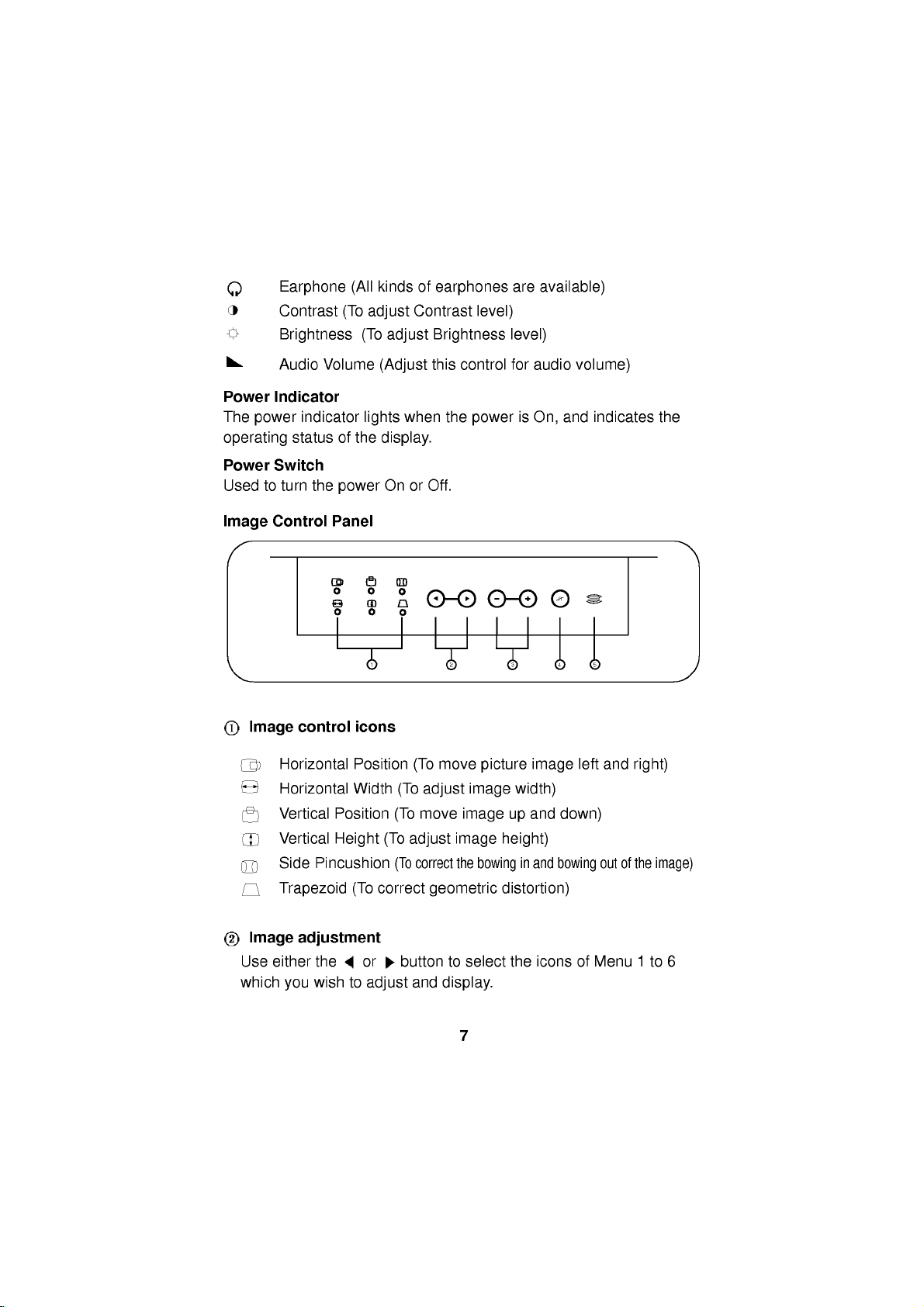
Image
indicator
status
turn
the
control
Horizontal
Horizontal
Vertical
Vertical
Side
Pincushion
Trapezoid
of
the
power
Panel
icons
Position
Width
Position
Height
(To
lights
display.
On
1
(To
(To
correct
when
or
(To
adjust
(To
the
Off.
2
move
(To
adjust
move
correct
geometric
power
image
image
image
the
bowing
is
picture
width)
up
height)
in
distortion)
On,
image
and
and
and
U
4
left
down)
bowing
indicates
53
and
out
of
the
right)
the
image)
Image
Use
which
adjustment
either
you
the
wish
to
or
buttontoselect
adjust
and
display.
7
the
iconsofMenu
1
to
6
Page 10

-/+
Used
item
Degauss
This
accurate
Mic
On
the
use
Condenser
the
rear
sound
buttons
to
set
by
pressing
button
front
of
card
digital
button
is
image
panel
the
(if
values
+
button
used
to
and
color.
there
Microphone,
monitor
(Mic
available).
for
each
for
increment
demagnetic
is
a
Condenser
you
out)
and
of
need
the
select
-
or
the
Microphone.
to
use
into
the
on
screen
button
for
decrement.
picturetogive
In
order
a
cable
to
plug
Mic
input
jack
control
a
into
of
your
more
to
To
adjust
Press
1)
an
adjust.
Press
item
either
will
2)
3)Toadjust
4)
Any
image
the
monitor's
General
After
following
section
operate
1.
2.
3.
on
Turn
on
monitor's
Turn
on
After
the
booting
power
check
manual.
4.While
icons
the
looking
Menu
prefer.
the
image
select
image
+
the
show
the
other
controls,
adjustments
memory.
Operation
the
control
the
the
LED
monitor.
monitor
power
PC.
(the
on
connections
at
1
to
layout
indicator
the
the
6
controls:
button
-
or
button
item
level
general
and
by
PC
monitor
image
and
(
to
and
repeat
you
installation
function,
pressing
will
power-up
and
on
+
press
or
)tohighlight
the
adjust
effect
of
above
make
steps
will
directions
you
the
power
amber.
light
sequence
should
the
the
be
trouble-shooting
screen,
-
or
button
an
item
image.Adisplay
pushing
1)
be
automatically
are
ready
button
illuminated
select
for
image
-
the
or
and
2).
and
reviewing
to
power-up
once.
and
initialization)
green.
section
the
image
adjustment
you
+
The
for
keys.
stored
wish
that
the
and
the
If
not,
of
this
control
you
to
in
8
Page 11
Power
This
monitor
during
(DPMS)
(VESA),
for
reduced
For
the
either
software.
saving
When
power
power
mouse
energy
Management
idle
a
operation
the
indicator
indicatorisamber
by
incorporates
time,
following
guide-lines
andiscertified
power
power
PC
having
The
power
pointer
turning
usage.
savings
power
monitor
is
indicatedbythe
indicator
is
amber,
or
touch
off
of
feature
the
System
the
the
as
saving
has
the
and
a
monitor.
new
circuitry
Display
Video
Electronics
exceeding
to
operate,
circuitry
three
power-saving
power
is
green,
monitor
wish
you
keyboard
for
Power
the
lowering
Management
Standards
EPA's
the
monitor
or
a
PC
indicatoronthe
operation
in
is
a
power
to
use
the
button.
When
Energy
must
running
states,
is
normal.
saving
PC
again,
screen
not
energy
Association
Star
be
and
front
mode.
move
in
usage
Signalling
program
used
with
blanking
the
power
panel.
When
the
If
the
your
save
use,
Image
This
monitor
following
position,
of
any
the
turn
NOTE:
in
640x480
this
image
image
your
between
each
More
the
adjustments
off
the
The
the
event
event,
display
settings
640x480
of
on
Adjustment
has
a
items:Horizontal
side
above
monitor
video
you
a
640x480
the
image
microprocessor-based
pincushion
items,
you
and
time
only
you
change
mode
may
desire.
you
made
you
image
specific
memory
and
the
made.
turn
you
video
in
DOS
need
in
settings
mode
image
modes
horizontal
width,
trapezoid.
microprocessor
Your
settings
it
on
again
need
may
modes
to
an
800x600
to
Now
the
anda800x600
the
adjust
the
microprocessor
800x600
before.
settings
in
the
to
you
control
When
will
at
some
adjust
(for
image
video
From
made
video
system
position,
you
will
automatically
be
maintained
later
the
image
example,
video
controls
mode,
now
mode,
in
memory
make
time.
you
mode
will
having
on,
the
each
for
vertical
adjustments
settings
may
for
again
memorize
already
when
monitor
of
these
modes
adjusting
height
memorize
if
even
again
from
go
windows).
to
meet
the
stored
switch
you
will
recall
modes.
section.
the
and
to
you
is
a
In
the
new
9
Page 12

Video
This
detect
scanning
Memory
multi-synchronous
and
range
convenience,
come
from
below.
display
of
the
the
factory
Modes
several
30-50KHz
monitor
auto-scanning
video
Horizontal
17
has
a
preset
to
modes
mode
popular
monitor
falling
and
50-90Hz
memory
video
can
within
modes
automatically
the
Vertical.
of
which
as
monitor's
5
modes
described
For
Mode
1
2
3
4
5
If
the
video
you
may
that
factory
blank
now
will
alsobestoredinmode
to
the
image
Mode
Display
VGA640
VGA640
VESA640
SVGA/VESA75,800
1024x768
Modes6-17
monitor
it
card,
have
had
not
presets,
(empty)
the
adjust
mode
settings
x
400
x
480
x
480
detects
will
been
that
Horizontal
Frequency
31.47
31.47
37.50
x
600
46.88KHz
48.40
are
made
and
empty
one
recall
that
before.Ifthe
present
will
it
store
memory
image
will
modes
controls
the
monitor
alsoberecalled.
KHz
KHz
KHz
KHz
can
of
mode
before
a
6.
accept
the
to
Whenever
Vertical
Frequency
70
Hz
60
Hz
75
Hz
75
Hz
60
Hz
new
video
above
and
any
monitor
or
is
new
mode
this
(in
your
example,
preference,
your
recognizes
Polarity
Horiz
sync
Verti
-
-
-
+
-
data.
signals
from
stored
detects
not
one
automatically
mode
these
video
card
as
mode
sync
+
-
-
+
-
image
a
new
of
the
6,
Comments
Factory
may
user's
by
your
computer's
adjustments
video
above
in
one
When
6).
image
or
PC
your
but
fixed,
be
updated
setting.
mode
listed
of
the
you
settings
switches
personal
10
Page 13

A
note
There
than
you
factory
left
blank
new
video
and
new
If
use
you
that
do
factory,
As
1)
the
thisisthe
If
2)
you
monitor
mode
If
even
3)
mode
summary,
last
about
are
will
fixed
(empty).
modes,
mode
a
not
here's
the
new
have
17
mode
the
a
total
of17video
use
at
modes
If
the
added
video
card
correspond
what
monitor
information
first
used
has
another
of
the
more
new
becomes
if
the17modes
17
repeatedly.
video
any
that
you
monitor
in
that
will
encounters
new
up
last
modes
the
memory
one
time.Ofthese
cannot
use
up
the
last
hasanumber
to
any
happen:
in
the
data
encountered).
modes
mode
mode.
are
17th
mode
modes:
memory
be
changed.
the12blank
will
only
17.
mode
of
the
monitor
new
video
next
available
6-17
with
it
encounters,
encountered
and
are
full
and
modes,
delete
of
12
the
generally
17
modes,
The
modes
modes
resolutions
video
data,
empty
new
will
it
by
old
new
modes
5
remaining
and
6ofthe
and
modes
the
monitor
mode
video
modes,
store
the
monitor,
mode
6isdeleted.
are
more
are
permanent,
12
still
have
last
frequencies
set
will
(mode
the
new
each
added
modes
modes
at
and
data
more
mode
save
at
new
the
6
the
the
if
in
In
By
designing
common
with
Example:All
1234567
m1m2m3m4m5m6m7
factory
When
1234567
m1m2m3m4m5m7m8
factory
your
12
own
the
video
image
17
modes
fixed
new
dataisencountered
fixed
"m6"
monitor
modes
settings
are
old
mode6deleted
this
way,
generated
recalled
filled
with
new
(
will
you
by
your
automatically.
11
following
151617
m15
data
becomes
151617
m16
always
graphics
m16
m17
have
data
m17
mode
m18
card
mode
data
18)
the
most
available,
Page 14

Audio
Features
A
major
featureofthis
conveniently
taking
easily
your
up
upgrade
PC
with
any
significantly
Audio
Use
andtothe
left
use
Otherwise,
control
An
monitor
DDC
DDC
automatically
monitor
and
and
the
DDC2AB
example,
screen
NOTE:
Connections
the
supplies
sound
and
right
the
PC
to
the
the
lower
additional
and
(Display
isacommunication
has
DDC2B
the
monitor.
monitor
has
the
with
PC
must
monitorisit's
integrates
more
to
sound
less
cabling
channel
turn
volume
a
space.
audio
capable
cardtothe
and
cabletoattachtothe
in
card
your
signals
the
up
control
volume
coming
"SPEAKER
connect
informs
three
carry
but
the
Data
the
PC
PC
support
the
Channel)
DDC
out
Under
not
function
can
keyboard.
sound
the
functions;
uni-directional
these
commands
fetch
DDC
stereo
By
volume
IN"
host
screen
space
in
connector
of
built-in
audio
amplifier
designing
multimedia
bach
of
requirements.
rear
PC
(line
out).
the
one
of
the
on
the
monitor
out
of
in
card
channel
your
system(PC)
DDC1,
communication
situations,
to
control
bi-directional
data
functions
audio
system.
and
speakers
the
monitor
like
this,
applicationsbyattaching
this
wire.
sound
the
is
to
monitor.
of
The
sound
located
over
DDC2B,
the
from
do
the
Make
card
front
PC
about
PC
the
monitor
this.
will
It
monitor
will
cable
sure
when
all
the
will
panel
card.
on
the
rear
(speaker
which
sends
communication.
out).
the
its
capabilities.This
DDC2AB.
between
display
monitor
and
This
without
you
result
(audio
both
carry
you
way.
only
of
monitor
the
data
servings.
adjust
can
in
in)
the
DDC1
PC
to
For
the
12
Page 15
Troubleshooting
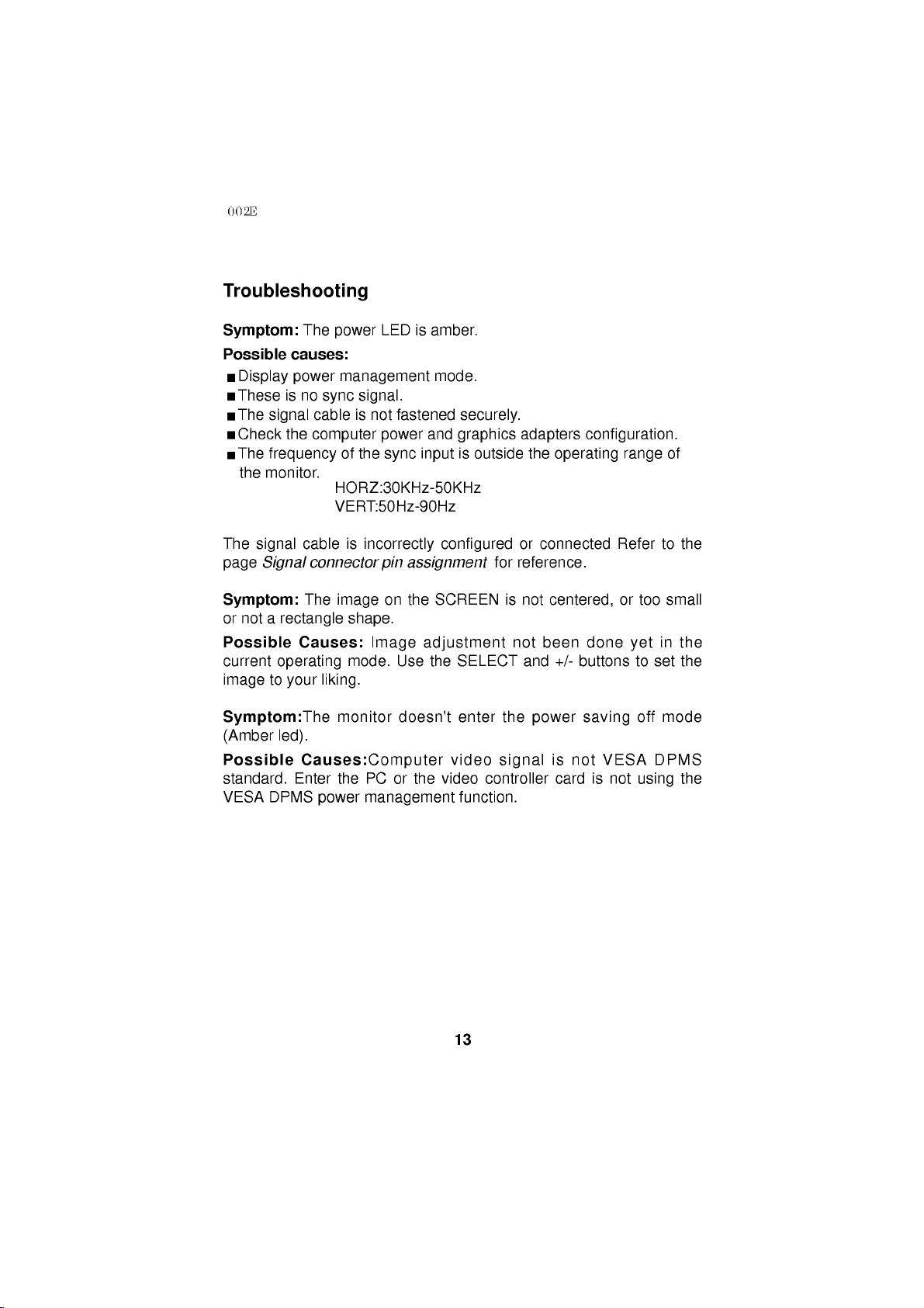
Symptom:
Possible
causes:
Display
These
The
Check
The
the
The
page
is
signal
the
frequency
monitor.
signal
Signal
Symptom:
or
not
a
rectangle
Possible
current
image
operating
to
your
Symptom:The
(Amber
Possible
standard.
VESA
led).
DPMS
The
power
no
cable
computer
cable
connector
The
power
sync
VERT:50Hz-90Hz
LED
management
signal.
is
not
power
of
the
sync
HORZ:30KHz-50KHz
is
incorrectly
pin
on
image
shape.
Causes:
Image
mode.
liking.
monitor
Causes:Computer
Enter
the
PC
power
management
is
amber.
mode.
fastened
and
input
configured
assignment
the
SCREEN
adjustment
Use
the
doesn't
or
the
securely.
graphics
is
outside
SELECT
enter
video
video
function.
adapters
the
or
for
reference.
is
not
not
and
the
signal
controller
operating
connected
centered,
been
+/-
power
is
card
configuration.
range
Refer
or
too
done
yet
buttons
saving
not
is
VESA
not
to
off
using
to
in
set
mode
DPMS
of
the
small
the
the
the
13
Page 16
Service
1.
Unplug
qualified
The
Liquid
The
The
instructions.
the
service
power
has
monitor
monitor
operating
result
may
qualified
The
monitor
The
monitor
Snapping
while
the
make
occasional
video
modes.
2.
Do
not
attempt
removing
hazards.
3.
When
replacement
verifyinwriting
characteristics
replacements
monitor
personnel
cord
or
plugisdamaged
been
spilled
has
been
does
not
Adjust
instructions.
in
damage
technician
or
monitor
covers
Refer
to
has
been
exhibitsadistinct
popping
is
sounds
to
may
all
servicingtoqualified
parts
that
as
the
can
prevent
from
the
when
into
exposed
operate
those
only
An
improper
and
restore
dropped
from
operating.
when
service
expose
are
the
replacements
original
fire,
wall
the
monitor.
to
normally
outlet
:
or
rain
controls
and
frayed.
or
water.
following
that
adjustment
often
the
monitor
or
the
requires
cabinet
to
extensive
normal
has
changeinperformance.
the
monitor
Itisnormal
being
the
monitor
you
required,
parts.
shock
is
continuous
for
turned
on
yourself,asopening
to
dangerous
service
have
used
Use
and
the
have
of
manufacture
other
personnel.
refer
the
are
covered
of
operation.
been
some
or
off,
voltage
service
the
hazards.
servicing
operating
other
controls
work
damaged.
or
frequent
monitors
or
switching
or
technician
same
specified
to
in
the
by
to
or
other
safety
a
4.
Upon
completion
service technician
manufacturer's
5.
When
disposal
service
a
video
could
technician
of
service
monitor
result
to
any
to
perform
manual.
reaches
in
dispose
service
a
picture
or
repairs
the
safety
the
end
tube
of
the
monitor.
14
to
the
check
of
its
useful
implosion.
monitor,
described
life,
Ask
ask
in
improper
a
qualified
the
the
Page 17
Input
Specifications
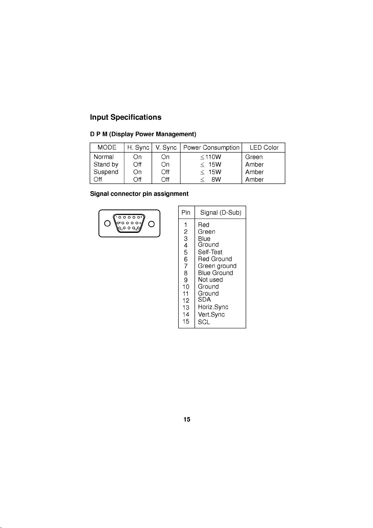
DPM
MODE
Normal
Stand
Suspend
Off
Signal
(Display
by
connector
1
6
11
Power
H.
Sync
On
Off
On
Off
15
pin
5
10
Management)
V.
Sync
On
On
Off
Off
assignment
Power
Pin
10
11
12
13
14
15
Consumption
110W
15W
15W
8W
Signal
Red
Green
Blue
Ground
Self-Test
Red
Green
Blue
Not
123456789
Ground
Ground
SDA
(D-Sub)
Ground
ground
Ground
used
Horiz.Sync
Vert.Sync
SCL
LED
Green
Amber
Amber
Amber
Color
15
Page 18
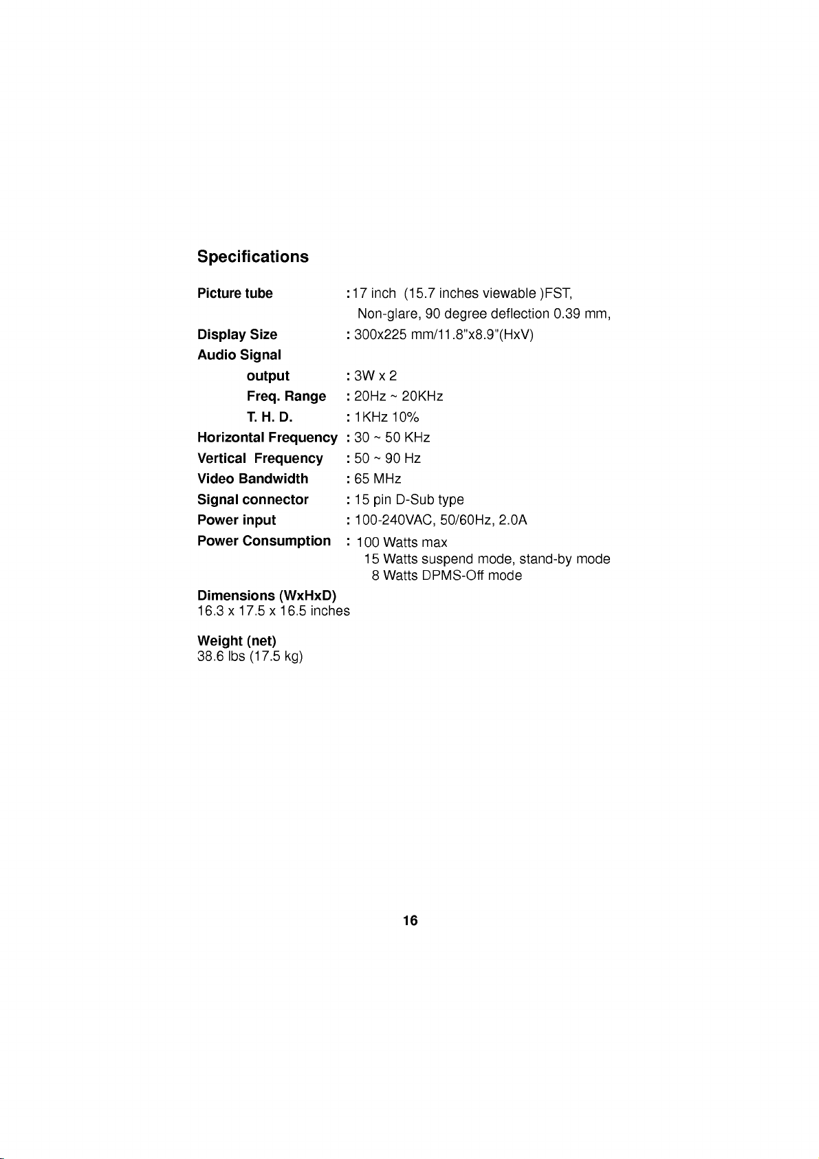
Specifications
Picture
Display
Audio
Horizontal
Vertical
Video
Signal
Power
Power
Dimensions
16.3x17.5x16.5
tube
Size
Signal
output
Freq.
Range
T.H.D.
Frequency
Frequency
Bandwidth
connector
input
Consumption
(WxHxD)
inches
:
17
inch
(15.7
inches
Non-glare,90degree
:
300x225
:3Wx2
:
20Hz~20KHz
:
1KHz
:
30~50
:
50~90
:
65
:
15
:
100-240VAC,
:
100
15
mm/11.8"x8.9"(HxV)
10%
KHz
Hz
MHz
D-Sub
pin
8
Watts
Watts
Watts
type
max
suspend
DPMS-Off
50/60Hz,
viewable
deflection
2.0A
mode,
mode
)FST,
0.39
stand-by
mm,
mode
Weight
38.6
lbs
(net)
(17.5
kg)
16
Page 19
MODEL
:
StudioWorks
74m
Page 20
FCC
Compliance
Statement
This
equipment
Class
are
equipment
B
designedtoprovide
and
a
limits
interference
This
energy,
instructions,
However,
particular
If
this
reception
on),
one
-
-
-
-
there
installation.
equipment
(which
the
user
or
more
Reorient
Increase
Connect
thattowhich
Consult
help.
Caution:
Electronics
to
operate
terminals,
be
attached
likely
Changes
the
printers,
to
resultininterference
has
digital
in
a
if
may
is
encouraged
of
the
or
relocate
the
the
the
Inc.
for
equipment.
to
this
been
tested
device
residential
pursuant
installation.
generates,
not
installed
cause
harmful
is
no
guarantee
does
cause
can
be
determined
following
separation
equipment
the
dealer
or
measures:
the
receiving
between
intoanoutlet
receiverisconnected.
or
an
modifications
compliance
Only
certified
etc.)
monitor.
Operation
to
and
found
to
Part
reasonable
uses
and
and
used
interference
that
interference
harmful
interference
by
to
to
correct
try
antenna.
the
experienced
not
could
void
peripherals
to
comply
radio
and
to
15ofthe
protection
can
in
turning
equipment
on a
radio/TV
expressly
the
(digital
with
with
non-certified
TV
comply
FCC
radiate
accordance
to
radio
will
to
radioortelevision
the
equipment
the
interference
and
circuit
different
technician
approved
user's
(or
input/output
the
Class
reception.
with
the
limits
Rules.
against
radio
communications.
not
These
harmful
frequency
with
occur
off
by
the
receiver.
from
for
by
your)
authority
devices,
B
limits
peripherals
for
the
in
and
using
LG
may
a
is
shielded
Only
Canadian
Suggested
This
Class
D.
text
Signal
O.
C
for
B
digital
Interference-Causing
Cet
appareil
du
Reglement
numerique
sur
Cables
Notice
the
notice
apparatus
le
may
indication
Equipment
delaclasse
materiel
be
used
meets
Regulations.
brouilleur
with
this
compliance
all
requirements
B
respecte
du
Canada.
System.
with
toutes
this
of
les
the
Standard:
Canadian
exigences
Page 21

 Loading...