

Page 1
Page 2
Page 3
ADJUSTMENT INSTRUCTIONS
*Alignment procedures
1.
It is safe to adjust after using insulating transformer between
the power supply line and chassis input to prevent the risk of
electric shock and protect the instrument.
2.Never disconnect leads while the TV receiver is on.
3. Don't short any portion of circuits while power is on.
4. The adjustment must be done by the correct appliances.
But this is changeable in view of productivity.
5. Unless other-wise noted, set the line voltage to 230V
10%, 50hz.
* Test Equipment required
1. VIF sweep generator
2. Color bar/cross-hatch pattern generator
3. DC power supply
4. Digital multi-meter
5. Color analyzer
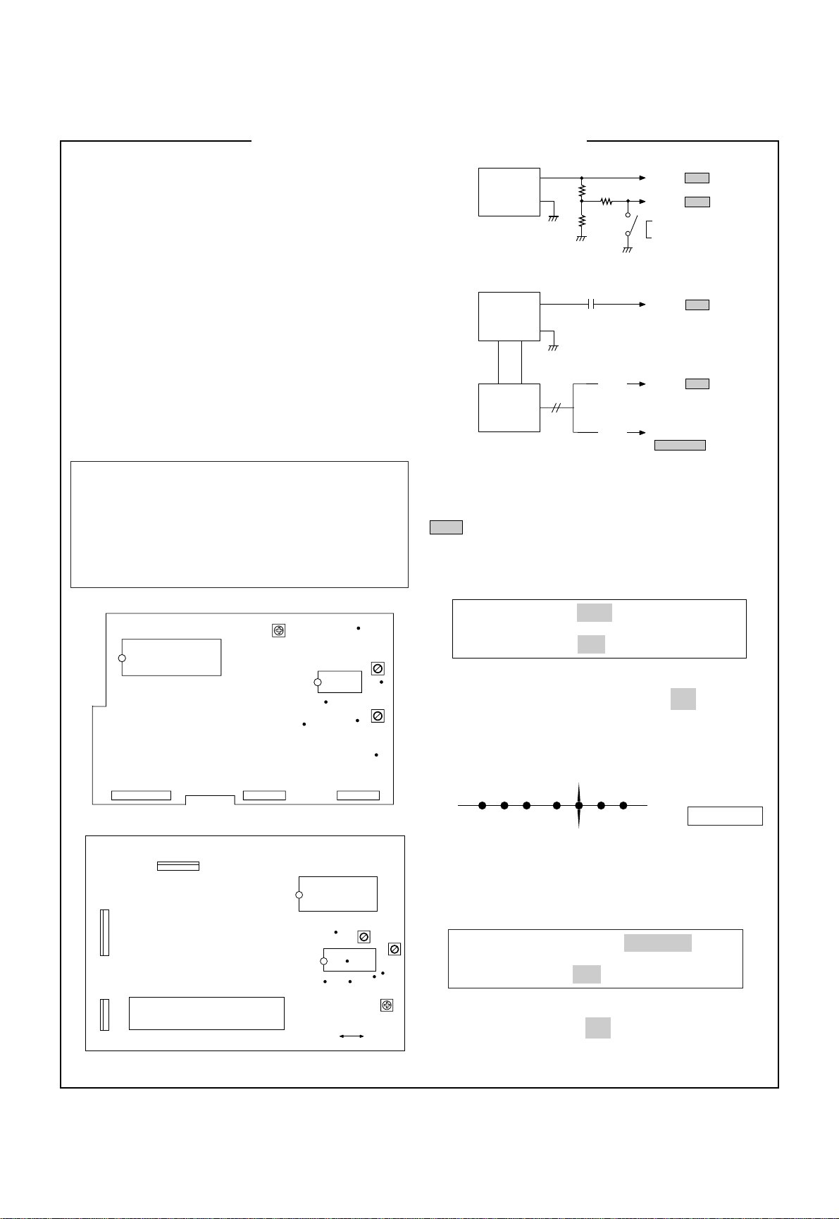
Preparation for VCO & AFT Adjustment
1. Connect the measuring equipment to the TV as shown in
Fig.1
2. Set RF output level of Sweep S.G (Signal Generator) to
80dBuV.
3. Set Alignment Scope, Volts/Div to 100mV (VCO) or
1V(AFT), AC/DC switch to AC, Line/Ext switch to Ext.
IF Board (Component side view)
TP1
TP21
IC1T
IC2P
TP22
IC1P
TP6
TP2
TP25
TP20
J21P
AGC TP
L8P
VCO
L9T
VCO
L8T
AFT
TP4
TP24
TP5
VR1P
AGC
TP23
VR1T
IC1S
PIP Board (Component side view)
P502B
P2B
P2B
TU2P
AGC
TP3
P102BP103B P101B
NOTE: TP point is on the copper side of PCB.
L9P
AFT
DC POWER
SUPPLY
+
12 0.1V
-
¡
SWEEP S.G.
with Marker
(VP-8800G)
Alignment
Scope
3.3K
4.7K
0.01µF
1K
(VCO)
(AFT)
To TP2/ TP21
To TP5/ TP24
VCO : ON
AFT : OFF
To TP1/ TP20
To TP6/ TP22
To Pin5 of P101B
/ Pin7 of P1B
Fig.1:Connection Diagram of Equipment for VCO & AFT
Adjustment.
NOTE:
:PIP Board (Only 2 TUNER PIP Model)
* VCO (Voltage Controlled Oscillator)
Adjustment
Test Point: TP6 / TP22
Adjust: L9T / L8P
1) Turn on DC power supply.
2) Adjust Video Detector Coil (L9T / ) so that a
L8P
waveform on Alignment Scope is the same as below Fig.2.
ABCDEFG
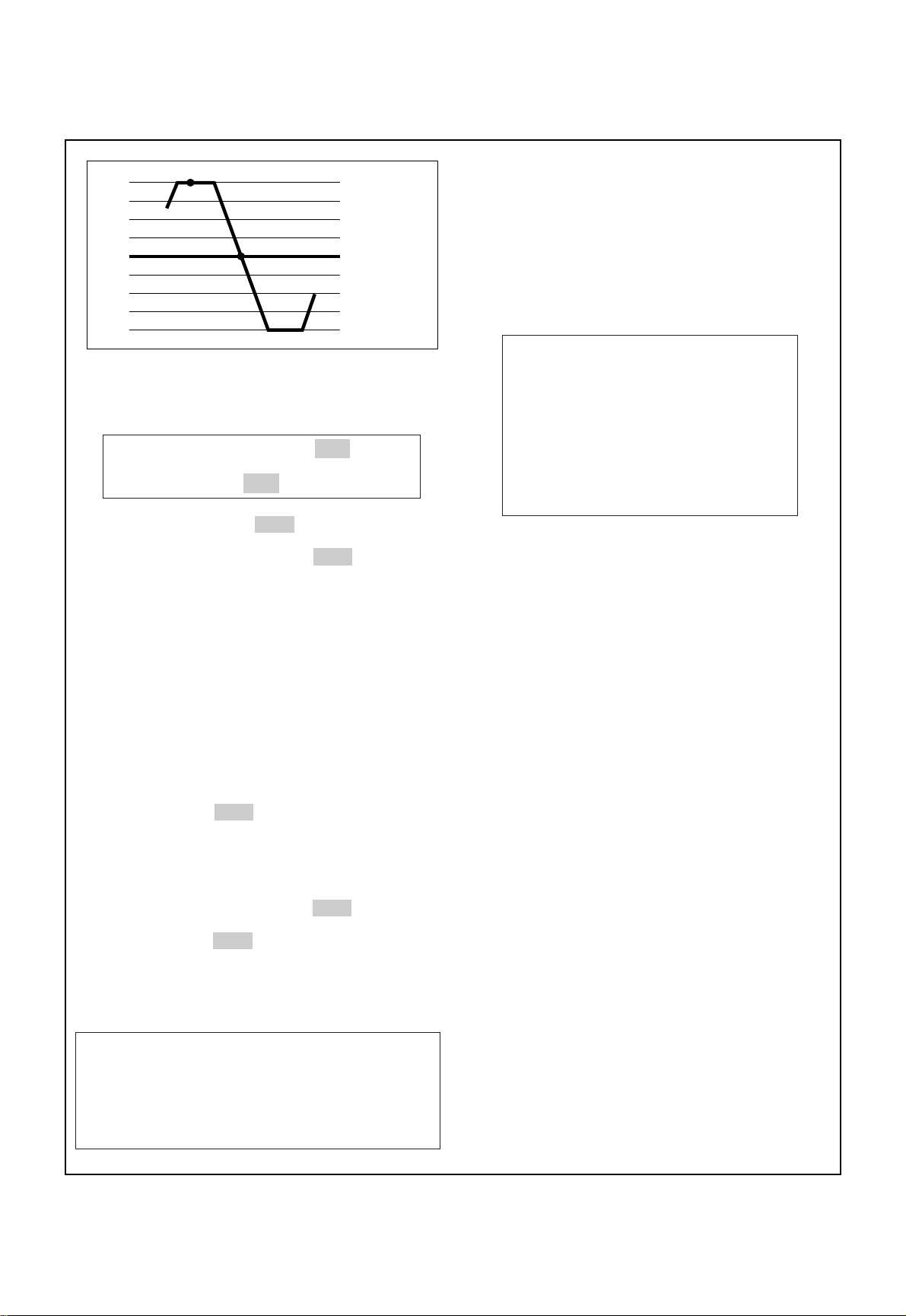
Fig.2: VCO waveform on Alignment Scope
* AFT(Auto Fine Tuning) Adjustment
Test Point: PIN5 of P101B / PIN7 of P1B
Adjust: L8T / L9P
1) Turn on DC power supply.
2) Adjust IF AFT coil (L8T / ) so that 38.0 MHz (Vc) point
will be center as Fig.3.
L9P
A: 30.0MHZ
B: 31.5MHZ
C: 32.84MHZ
D: 36.8MHZ
E: 38.0MHZ
F: 39.5MHZ
G: 40.25MHZ
Page 4
Adjustment procedures
1) Tune the TV set to receive a digital pattern unless
A
A: 36.8MHz
B: 38.0MHz
B
otherwise noted.
2) Press OK button on Control Board continuously and
yellow button on remote controller then you can find On
Screen Display. (Refer to the following Fig.4).
3) Press PR+ or PR- button for desirous function
adjustment.
4) Press VOL+ or VOL- button for correct picture.
5) Press OK button to memorize all the adjusted data.
[LINE SVC1] PR1
Fig.3: AFT waveform on Alignment Scope
* RF AGC (Auto Gain Control)Adjustment
Test Point: J1(on Main Board) / J22P
Adjust: VR1T / VR1P
The RF AGC control (VR1T/ VR1P ) was aligned at the time
of manufacture for optimum performance over a wide
range conditions. Readjust of VR1T/ VR1P should not be
necessary unless unusual local conditions exist, such as:
1) Channel interference in a CATV system.
2)Picture bending and/or color beats, which are unusually
due to excessive RF signal input when the receiver is
too close to a transmitting tower or when the receiver
is connected to an antenna distribution system where
the RF signal has been amplified.
In this case, the input signal should be attenuated (with
pad or filter) to a satisfactory level.
3) Picture noise caused by "broadcast noise" or weak
signal. If the broadcast is "clean" and the RF signal is at
least 1mV (60dBuV), the picture will be noise free in any
area.
Adjusting the VR1T/ VR1P (RF AGC) control to one end of
rotation will usually cause a relatively poor signal to noise
ratio;
Adjusting to the other end of rotation will usually cause a
degradation of over load capabilities resulting in color
beats or adjacent channel reference.
For best results, adjust the VR1T/ VR1P control while
performing on all over local channels, or the voltage at
J50(MAIN 1 Board) / J22P (PIP Board : OPTION) will be 5.5
+_0.1Vdc in RF level 60+_1dBuV.
VR1P
VR1P
VR1P
VR1P
J22P
H-CENT 11
V-CENT 02
SUB BRIGHT 10
SUB TINT 10
SECAM BELL 04
SECAM R-Y 08
SECAM B-Y 14
SECAM AMP 02
Fig.4
Horizontal center adjustment
Adjust so that the horizontal center line of digital pattern is in
accord with geometric horizontal center of the CPT.
Vertical center adjustment
Adjust so that the vertical center line of digital pattern is in
accord with geometric center of the CPT.
SECAM BELL filter adjustment
1) Tune the TV set to receive a SECAM digital pattern.
2)Adjust so that the color on the 3.8MHz pattern is
minimized.
SECAM B-Y/R-Y adjustment
1) Tune the TV set to receive a SECAM digital pattern.
2) Adjust so that the background color is equal to the PAL
background color.
* V
ertical center/Horizontal center/ SECAM
Adjustment
NOTE:These adjustments are already aligned at the time
of manufacture for optimum performance.
Readjust of them should not be necessary unless
IC2(EEPROM) is defective. Because all the
information of these adjustment are memorized in
that IC.
SECAM AMP adjustment
1) Tune the TV set to receive a SECAM digital pattern.
2) Adjust so that the level of SECAM color is equal to the
level of PAL color.
Page 5
SUB BRIGHT/TINT adjustment
NOTE: This adjustment should be performed after White
Balance adjustment.
1) Tune the TV set to receive a broadcasting signal.
Adjust so that the brightness/TINT is optimum condition
2)
on the screen.
NOTE: If press OK button on Control Board continuously and
press continually two times yellow button on remote
controller then you can find On Screen Display as
follow Fig.5.
* Never change these data, these are important reference
data for TV.
[LINE SVC2] PR1
PEAK LIMITER OFF
P/N GP INITIAL
SECAM GP INITIAL
P/N AMP 0
AV-IN VOL 044
FM PRESCALE 031
NICAM VOL 108
SCART VOL 040
Fig.5
2)Tune the TV set to receive white pattern of PAL
standard signal.
3) Press OK button on Control Board continuously and blue
button on remote controller for obtaining a horizontal
line on the middle of CPT.
4) Turn the screen control of FBT counter-clockwise and
set it to the minimum position.
5) Turn the screen control of FBT clockwise slowly to
appear a horizontal line.
6) Adjust Cut-off volume(VR901, 902, 903) so that the
horizontal line may become white.
First, except the appeared color on the horizontal line
with one volume and then make to be white line with
the other two volume.
7) Turn the Screen control counter-clockwise for the
horizontal line to be complet cut-off.
8) Press OK button.
9)With a color analyer (white balance checker), adjust
VR904 and VR905 on the CPT Board to set X position
+_8 and Y position to 294+_8 (color temperature
to 279
is 12000
10)Control contast and brightness to be 4.5ft.L color
temparature, and adjust VR901 and VR903 so that the
screen may become white.
11) By varing contrast and brightness, whether you have
good adjustment in high and low light areas on the
screen.
If not, re-adjust above setp 3)
+_800) at the high light (45ft.L).
~10).
*Vertical Height (VH)/Horizontal Width
(HW)/Pin Cushion (PC) Adjustment
1) Tune the TV set to receive a digital pattern.
2) Set contrast to 100%, brightness and color to 50%
individually.
3) Adjust VR301(VH) so that the circle of the digital pattern
may be located within the effective screen of the CPT.
4)Adjust VR404(HW) so that the circle of the digital
pattern looks like exact circle.
5) Adjust VR403(PC) so that the outermost left and right
vertical line looks like parallel with vertical lines of the
CPT.
* Screen & White Balance (color temperature)
Adjustment
NOTE:This adjustment should be performed after
warming up for 15 minutes at least.
Test Point: Observing Display
Adjust: Screen Control of FBT
VR901, 902, 903 (Low Light)
VR904, 905 (High Light)
* Focus Adjustment
NOTE: This adjustment should be performed after
warming up for 10 minutes.
Test Point: Observing Display
Adjust: Focus control of FBT
1) Set color to minimum, brightness and contrast to
maximum individually.
2) Tune the TV set to an inactive channel station (snow
condition).
3) Adjust the Focus control for best overall focus.
1) Set VR901, 902, 903, 904, 905 on CPT Board to the
mechanical center position.
Page 6

PURITY & CONVERGENCE ADJUSTMENT
Caution:
Convergence and Purity have been factory aligned. Do not
attempt to tamper with these alignments.
However, the effects of adjacent receiver components, or
replacement of picture tube or deflection yoke may require the
need to readjust purity any convergence.
DEFLECTION YOKE
PURITY &CONVERGENCE
MAGNET ASSEMBLY
6-POLE
,,,
RUBBER
WEDGES
,,
,,
,,,
PURITY MAGNET
4-POLE
GLASS CLOTH TAPE
X-AXIS YOKE
POSITIONING
(L/R PURITY)
5.Reconnect the internal degaussing coil.
6. Position the beam bender locking rings at the 9 o'clock
position and the other three pairs of tabs (2,4 and 6 pole
magnets) at the 12 o'clock position.
6-POLE
6-POLE
MAGNETS
4-POLE
MAGNET
MAGNES
CONVERGENCE MAGNET ASSEMBLY
CONVERGENCE MAGNET ASSEMBLY
PURITY MAGNET(2-POLE)
* Purity Adjustment
This procedure DOES NOT apply to bonded yoke and picture
tube assemblies.
The instrument should be at room temperature (60 degrees F or
above) for six (6) hours and be operating at low beam current
(dark background) for approximately 20 to 30 minutes before
performing purity adjustments.
CAUTION:Do not remove any trim magnets that may be
attached to the bell of the picture tube.
1. Remove the AC power and disconnect the internal
degaussing coil.
2. Remove the yoke from the neck of the picture tube.
3. If the yoke has the tape version beam bender, remove it and
replace it with a adjustable type beam bender (follow the
instructions provided with the new beam bender)
4. Replace the yoke on the picture tube neck, temporarily
remove the three (3) rubber wedges from the bell of the
picture tube and then slide the yoke completely forward.
7. Perform the following steps, in the order given, to prepare the
receiver for the purity adjustment procedure.
a. Face the receiver in the "magnetic north" direction.
b. Externally degauss the receiver screen with the television
power turned off.
c. Turn the television on for approximately 10 seconds to
perform internal degaussing and then turn the TV off.
d. Unplug the internal degaussing coil. This allows the
thermistor to cool down while you are performing the purity
adjustment. DO NOT MOVE THE RECEIVER FROM ITS
"MAGNETIC NORTH" POSITION.
e. Turn the receiver on and obtain a red raster by increasing
the red bias control (CW) and decreasing the bias controls
for the remaining two colors (CCW).
f. Attach two round magnets on the picture tube screen at 3
o'clock and 9 o'clock positions, approximately one (1) inch
from the edge of the mask (use double-sided tape).
3-2
Page 7

1.ADJUST YOKE Z-AXIS FIRST
TO GET EQUAL BLUE
COLOR CIRCLES
MAGNETS
RED RED
2 .ADJUST BEAM BENDER 2 POLE
MAGNET TO GET FOUR EQUAL
COLOR CIRCLES
8. Referring to above, perform the following two steps:
a. Adjust the yoke Z-axis to obtain equal blue circles.
b. Adjust the appropriate beam bender tabs to obtain correct
purity (four equal circles).
9. After correct purity is set, tighten the yoke clamp screw and
remove the two screen magnets.
10.Remove the AC power and rotate the receiver 180 degrees
(facing "magnetic south").
11. Reconnect the internal degaussing coil.
12. Turn the receiver on for 10 seconds (make sure the receiver
came on) to perform internal degaussing, and then turn the
receiver off.
13. Unplug the internal degaussing coil.
14. Turn on the receiver and check the purity by holding one (1)
round magnet at the 3 o'clock and a second round magnet at
9 o'clock position. If purity is not satisfactory, repeat steps 8
through 14.
15. Turn off the receiver and reconnect the internal degaussing
coil.
* Convergence Adjustment
Caution:This procedure DOES NOT apply to bonded yoke and
picture tube assemblies.
Do not use screen magnets during this adjustment
procedure. Use of screen magnets will cause an
incorrect display.
1. Remove AC power and disconnect the internal degaussing
coil.
2. Apply AC Power and set the brightness to the Picture Reset
condition. Set the Color control to minimum.
3. Apply 8V to the pin.
6. Reconnect the internal degaussing coil and apply AC power.
7. Turn the receiver on for 10 seconds to perform internal
degaussing and then turn the receiver off again.
8. Unplug the internal degaussing-coil.
9. Turn on the receiver, connect a signal generator to the VHF
antenna terminal and apply a crosshatch signal.
Caution:During the convergence adjustment procedure, be
very careful not to disturb the purity adjustment tabs
are accidentally move, purity should be confirmed
before proceeding with the convergence adjustments.
Note:
Make sure the focus is set correctly on this instrument
before proceeding with the following adjustment.
10. Converge the red and blue vertical lines to the green vertical
line at the center of the screen by performing the following
steps (below TABLE).
a. Carefully rotate both tabs of the 4-pole ring magnet
simultaneously in opposite directions from the 12 o'clock
position to converge the red and blue vertical lines.
b. Carefully rotate both tabs of the 6-pole ring magnet
simultaneously in opposite directions form the 12 o'clock
position to converge the red and blue (now purple)
vertical lines with the green vertical line.
11. Converge the red and blue horizontal with the green line at
the center of the screen by performing the following steps.
(below TABLE)
a. Carefully rotate both tabs of the 4-pole ring magnet
simultaneously in the same direction (keep the spacing
between the two tabs the same) to converge the red and
blue horizontal lines.
b. Carefully rotate both tabs of the 6-pole ring magnet
simultaneously in same direction (keep the spacing
between the two tabs the same) to converge the red and
blue (now purple) horizontal lines with the green
horizontal line.
c. Secure the tabs previsouly adjusted by locking them in
place with the locking tabs on the beam bender.
4. Adjust the Red, Green and Blue Bias controls to get a dim
white line.
5. Remove the AC power and 8V from the pin.
3-3
Page 8

3-4
RING
PAIRS
4
POLE
ROTATION DIRECTION
OF BOTH TABS
OPPOSITE
SAME
OPPOSITE
SAME
MOVEMENT OF RED
AND BLUE BEAMS
B B
RR
OR
OR
B R B R
OR
B
R
B
R
B R
OR
B
R
6
POLE
12. While watching the 6 o'clock positions on the screen, rock the
front of the yoke in a vertical (up/down) direction to converge
the red and blue vertical lines. (Fig upper left)
13. Temporarily place a rubber wedge at the 12 o'clock position
to hold the vertical position or the yoke.
14.
Check the 3 o'clock and 9 o'clock areas to confirm that the red
and blue horizontal lines are converged.
If the lines are not converged, slightly offset the vertical tilt of the
yoke (move the rubber wedge if necessary) to equally balance the
convergence error of the horizontal lines at 3 o'clock and 9 o'clock
and the vertical lines at 6 o'clock and 12 o'clock.
15. Place a 1.5 inch piece of glass tape over the rubber foot at
the rear of the 12 o'clock wedge.
16. While watching the 6 o'clock and 12 o'clock areas of the
screen, rock the front of the yoke in the horizontal (left to
right) motion to converge the red and blue horizontal lines.
(Fig. upper right)
17. Temporarily place a rubber wedge at the 5 o'clock and 7
o'clock positions to hold the horizontal position of the yoke.
18. Check the 3 o'clock and 9 o'clock areas to confirm that the
red and blue vertical lines are converged. If the lines are not
converged, slightly offset the horizontal tilt of the yoke (move
the temporary rubber wedges if necessary) to equally
balance the convergence error of the horizontal lines at 6
o'clock and 12 o'clock and the vertical lines at 3 o'clock and 9
o'clock.
19. Using a round magnet confirm purity at the center, right and
left sides and corners. See Purity Adjustment Procedure.
20. Reconfirm convergence and apply a 1.5 inch piece of glass
tape over the rubber foot at the rear of the 5 o'clock and the 7
o'clock wedges.
RED
BLUE
RED BLUE
BLUE
RED
GREEN
GREEN
BLUE RED
GREEN
GREEN
ADJUSTMENT
VIEWING
AREA
UP/DOWN ROCKING OF THE YOKE
CAUSES OPPOSITE ROTATION OF RED
AND BLUE RASTERS
ADJUSTMENT
VIEWING
AREA
RED
RED
GREEN
TV
SCREEN
LEET/RIGHT ROCKING OF THE YOKE
CAUSES OPPOSITE SIZE CHANGE OF
THE RED AND BLUE RASTERS
UP/DOWN ROCKING OF THE YOKE
CAUSES OPPOSITE ROTATION OF RED
AND BLUE RASTERS
LEFT/RIGHT ROCKING OF THE YOKE
CAUSES OPPOSITE SIZE CHANGE OF THE
RED AND BLUE RASTERS
Page 9

NO PICTURE/
NO COLOR
Is the CVBS signal of
pin3 of P102A normal?
Is the CVBS signal of
Pin40 of IC201 normal?
Is the Y signal of Pin25
of IC503 normal?
Is the Y signal of Pin60
of IC501 normal?
Are R-Y, B-Y signal of
Pin37,38 of IC503 normal?
Are R.G.B signal of Pin16,
17, 18 of IC503 normal?
Check CPT Board
Check IF Board
Check/Replace
IC201
Check/Replace
IC202, IC204, IC205
Check/Replace
IC503
Check/Replace
IC502
Check/Replace
IC503
Yes
Yes
Yes
Yes
Yes
Yes
No
No
No
No
No
No
Page 10

NO PIP
In case of Main/AV PIP
In case of sub PIP
Is the video signal of
pin29 of IC201?
Is the video signal of
pin26 of IC2P
Check pin1, 2, 3
of IC2P
Check pin5, 6, 7, 8
of IC5P
Check pin 1, 4, 6, 8
of IC704
Check/Replace
IC703, IC704
Is the CVBS signal of
pin24 of IC2P?
Check
TUNER/IF parts
of PIP Board
Check/Replace
IC4P, IC5P
Check P2A, P2B
Check/Replace
IC2P, IC7P
Check P502A,
P502B
Check/Replace
IC201
Check I
2
C Bus
No
No
No
Normal
Normal
Normal
Yes
Yes
Yes
Abnormal
Abnormal
Abnormal
Page 11

NO TELETEXT
Check the voltage 12V
of C726
Check the 12V line
to be correct
Check/Replace
IC201
Check/Replace
IC705, D701
Check whether video
signal is in at the pin40
of IC201 or not
Check the CVBS line
Check/Replace
IC701, IC706
Check the voltage of C725
Check whether video signal
is in at pin 3 of IC702 or not
Check I2C Bus lines
(SDA, SCL)
Check pin 19, 20, 22, 23
of IC701
Check/Replace
IC704
Abnormal
Abnormal
No
Abnormal
No
Yes
Yes
OK
Normal
Normal
4.8
~ 5.2V
Page 12

NO PICTURE/NO SOUND
(RASTER OK)
Does the Auto search
operation?
Is the CVBS signal of
Pin3 of P102A normal?
GO TO
NO PICTURE Block
NO SOUND Block
Check the voltage
33V, 5V of Tuner
Check the pin 3, 16,
19, 20, 21 of IC1
Check/Replace
ZD101, ZD102, R155
Check IF Board
No
OK
OK
NGNo
Yes
Yes
Page 13

NO RASTER
(SOUND OK)
Check the voltage of
CPT Heater
Check the voltage of
HV, SCREEN of CPT
Check/Replace
CPT Board
Check the Heater
pulse of pin9 of T402
Check/Replace
Connector, FR901,
R443
Check/Replace
T402
Check/Replace
T402
Abnormal
Normal
Abnormal
Abnormal
Normal
Normal
Page 14

NO SOUND
(PICTURE OK)
Check Sound system of
MENU OSD
Is the voltage of Pin39
of IC1 0V(Low)?
Is the SIF signal of Pin22
of IC1T normal?
Are the Audio signal of
Pin28, 29 of IC1S normal?
Are the Audio signal of
Pin2, 5 of IC601 normal?
Are the Audio signal of
Pin7, 11 of IC601 normal?
Check/Replace
P601, P602, Speaker
Check/Replace
IC1T
Check/Replace
X1S, IC5S, IC1S
Check/Replace
IC2S, IC3S, IC4S
Check the voltage
of Pin10 of IC601
Is the voltage of pin39
of IC1 5V(High)?
5.5/6.0/6.5 4.5
Yes
Yes
Yes
Yes
Yes
No
No
No
No
Yes
Page 15

NO RASTER
Check +B voltage
at J401
Is the voltage at
Pin5 of IC501 9.1V?
Does the square
waveform from pin6
of IC501 appear?
Is the waveform of
collector of Q401 normal?
Is the waveform of
collector of Q402 normal?
Check/Replace
T402
Check/Replace
F801A, D801, IC801
Check/Replace
D801
Check/Replace
D802, D806,
D807, Q800,
IC801
Check/Replace
IC501
Check/Replace
Q401, T401,
R416, R417
Check/Replace
Q402
Check the
voltage 5V,
9V, 12V line
Check I2C Bus
lines (SDA,
SCL)
Check F801A
Check the voltage
of C808
Check the voltage
of pin9 of IC801
Check/Replace
IC802, D803, D808
Check the secondary
voltage are shorted
Normal 0V
OK
150~ 380V
6~ 8V
Open
0V
Lower than 6V
No
No
No
No
Yes
Yes
Yes
Yes
Yes
Page 16

 Loading...