

LG 900B, CB997G-EL Full
COLOR MONIT OR
SER VICE MANUAL
Website:http://biz.LGservice.com
E-mail:http://www.LGEservice.com/techsup.html
CAUTION
BEFORE SERVICING THE UNIT,
READ THE SAFETY PRECAUTIONS IN THIS MANUAL.
MODEL: StudioWorks 900B (CB997G-EL)
CHASSIS NO. : CA-123
F ACTORY MODEL: CB997G
*( ) ID LABEL Model No.
MENU SELECT
1. PICTURE TUBE
Size : 19 inch (Flat Slot Mask)
DefIection Angle : 90°
Neck Diameter : 29.1 mm
Phosphor : P22
Slot Pitch : 0.26 mm
Face Treatment : Anti-Glare
2. SIGNAL
2-1. Horizontal & Vertical Sync
1) Input Voltage Level: Low= ≤0.8V, High= ≥2.1V
2) Sync Polarity : Positive or Negative
2-2. Video Input Signal
1) Voltage Level : 0~0.7 Vp-p
a) Color 0, 0 : 0 Vp-p
b) Color 7, 0 : 0.467 Vp-p
c) Color 15, 0 : 0.7 Vp-p
2) Input Impedance : 75 Ω
3) Video Color : R, G, B Analog
4) Signal Format : Refer to the Timing Chart
2-3. Signal Connector
15 Pin D-Sub Connector
2-4. Scanning Frequency
Horizontal : 30~98 kHz
Vertical : 50~160 Hz
3. POWER SUPPLY
3-1. Power Range
AC 100~240V, 50/60HZ, 2.5A Max
AC 200~240V, 50Hz, 1.5A Max.(PFC version)
3-2. Power Consumption
4. DISPLAY AREA
4-1. Active Video Area :
• Max Image Size - 365.8 x 274.3mm (12.91" x 9.61")
• Preset Image Size - 350 x 262 mm (12.20" x 9.06")
4-2. Display Color : Full Colors
4-3. Display Resolution : 1600 Dots x 1200Lines
4-4. Video Bandwidth : 203MHz
5. ENVIRONMENT
5-1. Operating Temperature: 0°C~40°C (32°F~103°F)
(Ambient)
5-2. Relative Humidity : 8%~80%
(Non-condensing)
5-3. Altitude : 10,000 ft
6. DIMENSIONS (with TILT/SWIVEL)
Width : 448 mm (17.64")
Depth : 470 mm (18.50")
Height : 454 mm (17.87")
7. WEIGHT (with TILT/SWIVEL)
Net Weight : 19.0 kg (41.89 lbs)
Gross Weight : 22.5 kg (49.61 lbs)
CONTENTS
SPECIFICATIONS
- 2 -
SPECIFICATIONS ................................................... 2
SAFETY PRECAUTIONS ........................................ 3
TIMING CHART ....................................................... 4
OPERATING INSTRUCTIONS ................................ 5
CONTROL LOCATIONS ......................................... 6
WIRING DIAGRAM ................................................. 7
DISASSEMBLY ....................................................... 8
BLOCK DIAGRAM ................................................... 9
DESCRIPTION OF BLOCK DIAGRAM...................10
ADJUSTMENT ...................................................... 12
TROUBLESHOOTING GUIDE .............................. 14
EXPLODED VIEW.................................................. 21
REPLACEMENT PARTS LIST .............................. 23
PIN CONFIGURATION .......................................... 29
SCHEMATIC DIAGRAM......................................... 30
PRINTED CIRCUIT BOARD................................... 32
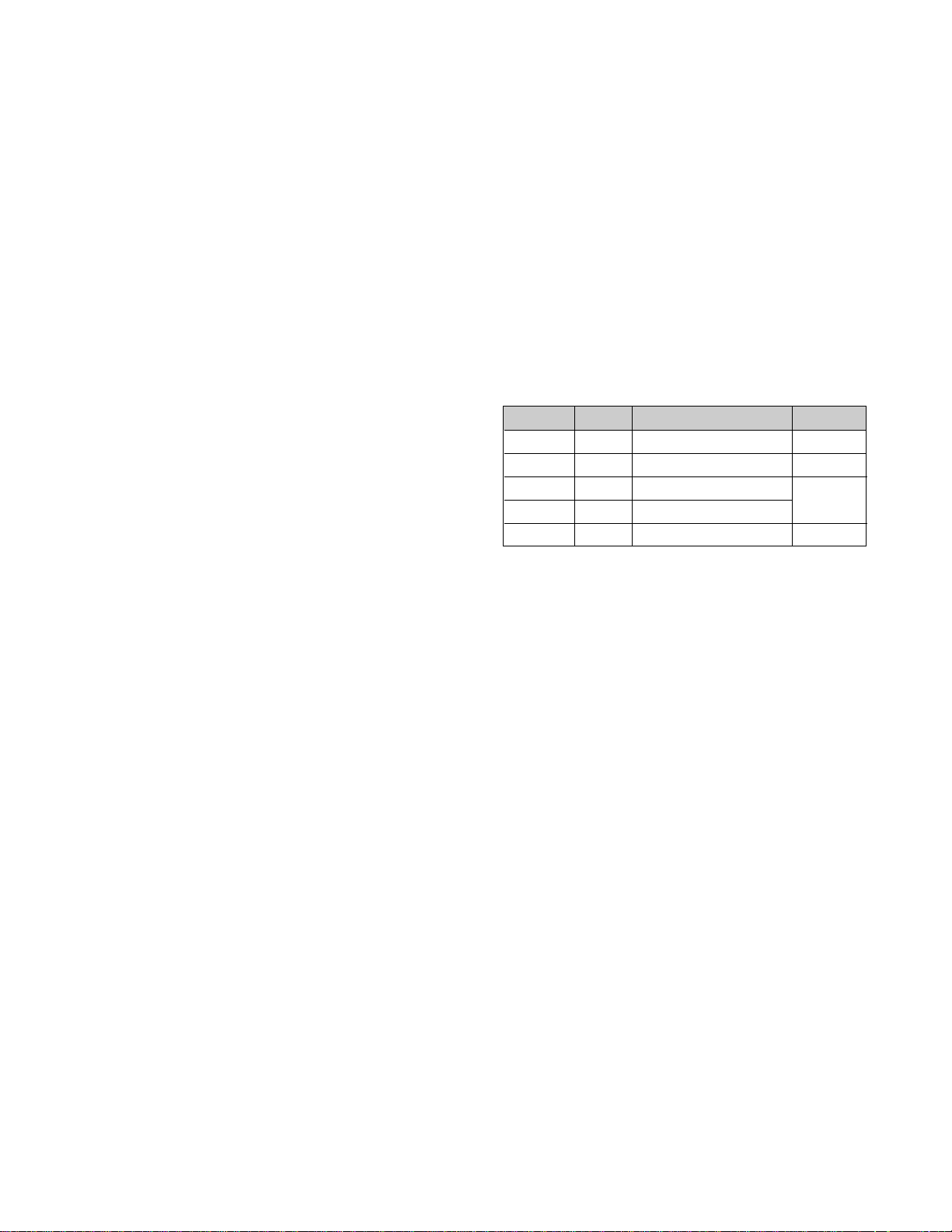
MODE
MAX
NORMAL (ON)
STAND-BY
SUSPEND
OFF
H/V SYNC
ON/ON
OFF/ON
ON/OFF
OFF/OFF
POWER CONSUMPTION
less than 110W
less than 83W
less than 8W
less than 8W
less than 3W
LED COLOR
GREEN
GREEN
AMBER
AMBER

SAFETY PRECAUTIONS
- 3 -
SAFETY-RELATED COMPONENT WARNING!
There are special components used in this color monitor
which are important for safety. These parts are marked
on the schematic diagram and the replacement
parts list. It is essential that these critical parts should be
replaced with the manufacturer's specified parts to
prevent X-radiation, shock, fire, or other hazards. Do not
modify the original design without obtaining written
permission from manufacturer or you will void the original
parts and labor guarantee.
CAUTION:
No modification of any circuit should be
attempted.
Service work should be performed only after
you are thoroughly familiar with all of the
following safety checks and servicing
guidelines.
SAFETY CHECK
Care should be taken while servicing this color monitor
because of the high voltage used in the deflection circuits.
These voltages are exposed in such areas as the
associated flyback and yoke circuits.
FIRE & SHOCK HAZARD
An isolation transformer must be inserted between the
color monitor and AC power line before servicing the
chassis.
• In servicing, attention must be paid to the original lead
dress specially in the high voltage circuit. If a short
circuit is found, replace all parts which have been
overheated as a result of the short circuit.
• All the protective devices must be reinstalled per the
original design.
• Soldering must be inspected for the cold solder joints,
frayed leads, damaged insulation, solder splashes, or
the sharp points. Be sure to remove all foreign
materials.
IMPLOSION PROTECTION
All used display tubes are equipped with an integral
implosion protection system, but care should be taken to
avoid damage and scratching during installation. Use only
same type display tubes.
X-RADIATION
The only potential source of X-radiation is the picture tube.
However, when the high voltage circuitry is operating
properly there is no possibility of an X-radiation problem.
The basic precaution which must be exercised is keep the
high voltage at the factory recommended level; the normal
high voltage is about 26kV. The following steps describe
how to measure the high voltage and how to prevent Xradiation.
Note : It is important to use an accurate high voltage
meter calibrated periodically.
• To measure the high voltage, use a high impedance
high voltage meter, connect (–) to chassis and (+) to
the CDT anode cap.
• Set the brightness control to maximum point at full
white pattern.
• Measure the high voltage. The high voltage meter
should be indicated at the factory recommended level.
• If the meter indication exceeds the maximum level,
immediate service is required to prevent the possibility
of premature component failure.
• To prevent X-radiation possibility, it is essential to use
the specified picture tube.
CAUTION:
Please use only a plastic screwdriver to protect yourself
from shock hazard during service operation.
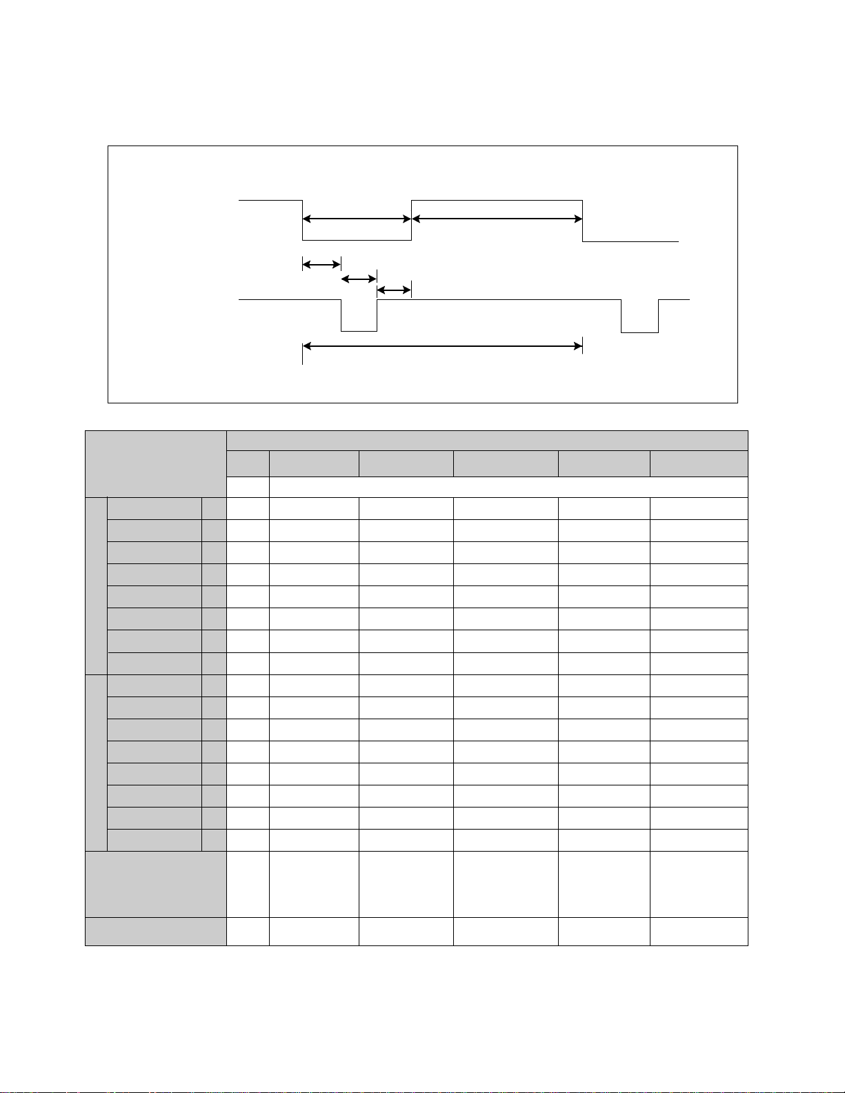
TIMING CHART
- 4 -
VIDEO
SYNC
D
A
E
F
BC
kHz
µs
µs
µs
µs
µs
µs
Hz
ms
ms
ms
ms
ms
ms
MODE 1
–
43.269
23.112
17.778
5.334
1.556
1.556
2.222
–
85.008
11.763
11.093
0.670
0.023
0.069
0.578
640
X
480
85Hz
Yes
MODE 2
+
53.674
18.631
14.222
4.409
0.569
1.138
2.702
+
85.061
11.756
11.178
0.578
0.019
0.056
0.503
800
X
600
85Hz
Yes
MODE 3
+
68.677
14.561
10.836
3.725
0.508
1.016
2.201
+
84.997
11.765
11.183
0.582
0.015
0.044
0.523
1024
X
768
85Hz
Yes
MODE 4
+
91.146
10.971
8.127
2.844
0.406
1.016
1.422
+
85.024
11.762
11.235
0.527
0.011
0.033
0.483
1280
X
1024
85Hz
Yes
MODE 5
+
93.750
10.666
7.901
2.765
0.316
0.948
1.501
+
75.000
13.333
12.800
0.533
0.011
0.032
0.490
1600
X
1200
75Hz
MARK
A
B
C
D
E
F
A
B
C
D
E
F
MODE
FACTORY PRESET MODE
Resolution
Recall
H
O
R
I
Z
O
N
T
A
L
V
E
R
T
I
C
A
L
Sync Polarity
Frequency
Total Period
Video Active Time
Blanking Time
Front Porch
Sync Duration
Back Porch
Sync Polarity
Frequency
Total Period
Video Active Time
Blanking Time
Front Porch
Sync Duration
Back Porch
VESA
* Mode 5 is not preset mode but TCO check resolution!
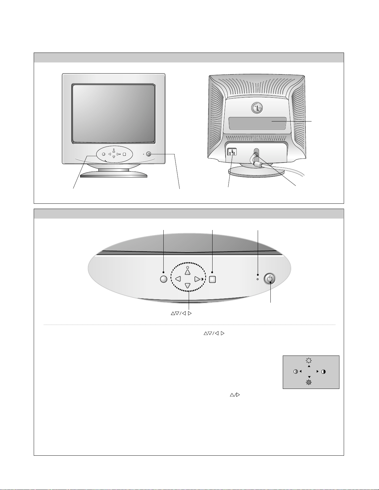
OPERATING INSTRUCTIONS
- 5 -
FRONT VIEW REAR VIEW
AC Power Socket
Signal Connector
ID Label
Front Control Panel
MENU SELECT
Power ON/OFF Button
See Front Control Panel
MENU SELECT
Buttons
MENU Button
Power Button
Power (DPMS) Indicator
SELECT Button
<Shortcut Keys>
• Brightness and Contrast can be
adjusted directly without entering
the On Screen Display (OSD)
system.
Press the buttons to adjust the settings and then the
MENU button to save all changes. The Brightness and
Contrast functions are also available in the On Screen
Display (OSD) menu.
100
100
1. Power ON/OFF Button
Use
this button to turn the monitor ON or OFF.
2. Power Indicator
This indicator lights up green when the monitor operates
normally; in DPMS (Energy Saving) mode, - stand-by,
suspend, or off mode -its color changes to orange, and
if abnormal or damaging circuit turns out orange blink.
3. Select Button
Use this button to enter a selection in the on screen
display.
4. Button
Use these buttons to choose or adjust items in the on
screen display.
5. MENU Button
Use this button to enter or exit the on screen display.
CONTROL LOCATIONS
- 6 -
VR801
: High Voltage Adjustment (26kV)
VR901: B Adjustment
+
(190V Line)
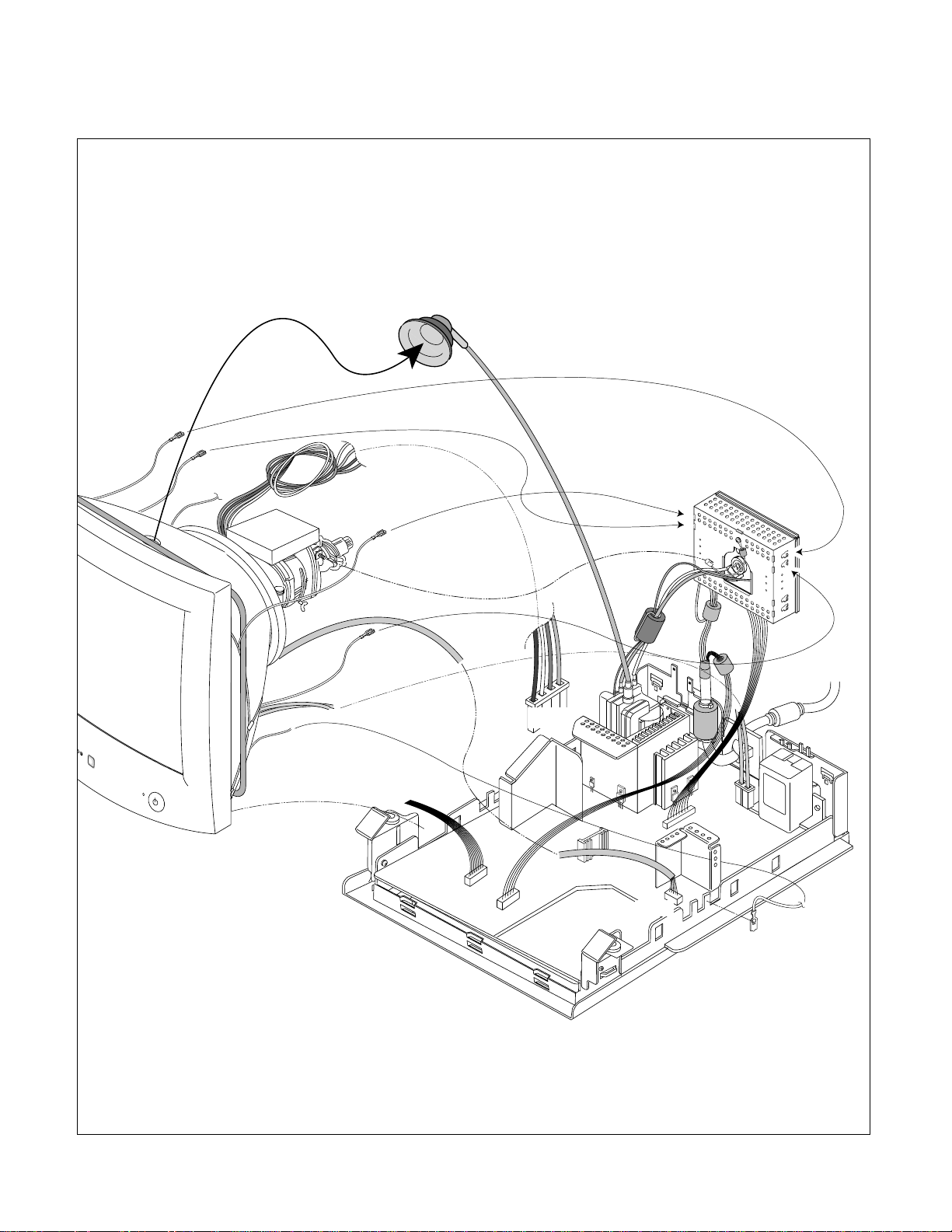
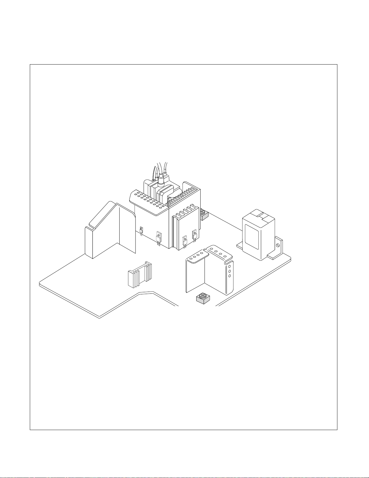
WIRING DIAGRAM
- 7 -
DY-Pin
Degaussing Coil
P702
P402
P401
P901
DY Assembly
Screw
P801
P201-
(Control PCB)
Anode Cap
P451
SELECT
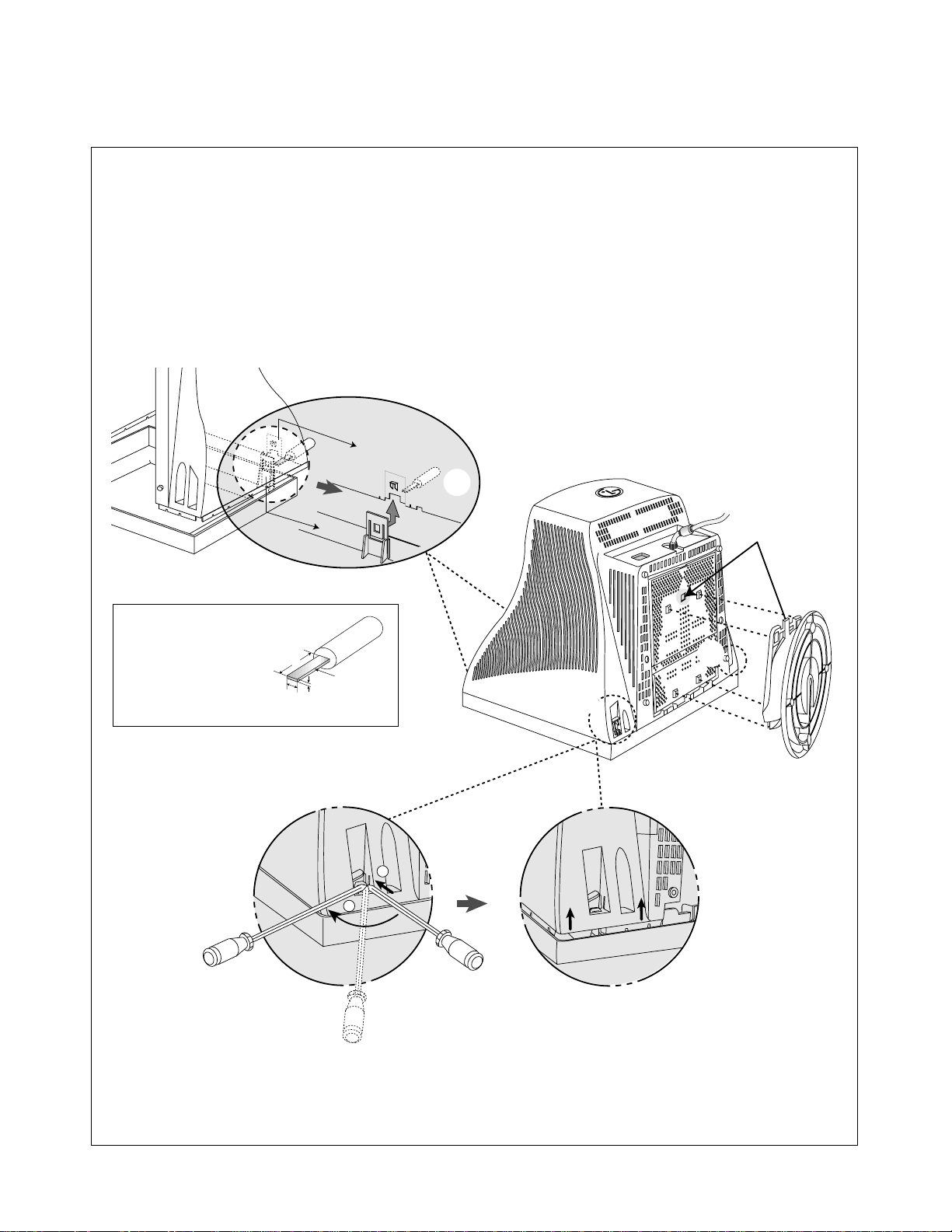
DISASSEMBLY
- 8 -
Tip Spec.
A(Width) : 5.0~13.0mm
B(Depth) : 0.6~0.9mm
C(Height) : 12.0mm
1. TILT/SWIVEL & BACK COVER REMOVAL
1) Set the monitor face downward.
2) Pull the latch (a), carefully remove the Tilt/Swivel by pulling it upward.
3) Pressing the latch (b), Back cover by pushing it upward.
4) Release the latch (c).
5) Slide the Back Cover away from the Front Cabinet of the monitor.
Back Cover
(c)
Cabinet
(a)
C
Tip
B
A
(b)
1
2
(b)
(b)
(b)

BLOCK DIAGRAM
- 9 -
SIGNAL
INPUT

DESCRIPTION OF BLOCK DIAGRAM
- 10 -
1. Line Filter & Associated Circuit.
This is used for suppressing noise of power input line
flowing into the monitor and/or some noise generated
in this monitor flowing out through the power input
line.
That is to say, this circuit prevents interference
between the monitor and other electric appliances.
2. Degauss Circuit & Coil.
The degauss circuit consists of the degaussing coil,
the PTC (Positive Temperature Coefficient) thermistor
(TH901), and the relay (RL901). This circuit eliminates
abnormal color of the screen automatically by
degaussing the slot mask in the CDT when turn on the
power switch.
When you need to degauss while using the monitor,
select DEGAUSS on the OSD menu.
3. SMPS (Switching Mode Power Supply).
This circuit works with power of 100~240V or
200~240V (50/60Hz) specially for PFC version.
The operation procedure is as follows:
1) AC input voltage is rectified and smoothed by
the bridge diode (D901) and the capacitor (C905).
2) The rectified voltage (DC voltage) is applied to the
primary coil of the transformer (T901).
3) The control IC (IC901) generates switching pulse
to turn on and off the primary coil of the
transformer (T901) repeatedly.
4) Depending on the turn ratio of the transformer, the
secondary voltages appear at the secondary coil of
the transformer (T901).
5) These secondary voltages are rectified by each
diode (D924, D926, D923, D922, D921, D920) and
operate the other circuits. (Deflection, Video
Amplifier, etc.)
4. Display Power Management Circuit.
This circuit control power consumption of the monitor
by detecting H and V sync signal. There are stand-by
and suspend mode. When no horizontal or vertical
sync signal input, the circuit consists of Q913 and
Q915 becomes stand-by and suspend mode. It’s
power consumption is below 8W. When no horizontal
and vertical sync signal input, it’s power consumption
is below 3W.
5. X-ray Protection.
This circuit detects the rectified DC voltage comes
from the FBT pin 4. If the high voltage of the FBT
reaches up to about 30kV (abnormal state), H.V
control (IC802) detects. It stops B+voltage supplied to
the FBT (T701), and high voltage is not be generated,
(In the normal state, the high voltage is about 26kV.)
6. Micom(Microprocessor) Circuit.
The operating procedure of Micom (Microprocessor)
and its associated circuit is as follows:
1) H and V sync signal is supplied from Signal Cable t o t h e
Micom (IC401).
2) The Micom (IC401) distinguishes polarity and
frequency of H and V sync.
3) The Micom controls each OSD function signals.
(H-size, H-position, V-size, etc.)
4) The controlled data of each mode is stored in IC402.
User can adjust screen condition by each OSD
function. The data of the adjust screen condition is
stored automatically.
7. Horizontal and Vertical Synchronous Processor.
This circuit generates the horizontal drive pulse and
the vertical drive pulse by taking sync-signal from
Signal Cable. This circuit consists of the
TDA4841(IC801) and the associated circuit.
8. Oscillating Circuit for D/D Converter.
This circuit generates the pulse wave which has the
horizontal period by taking the output of the TDA4841
(IC801).
9. D/D (DC to DC) Converter.
This circuit supplies DC voltage to the horizontal
deflection output circuit by decreasing DC 190V which
is the secondary voltage of the SMPS in accordance
with the input horizontal sync signal.
10. Side-Pincushion Correcting Cirucit.
This circuit improves the Side-pincushion of the
screen by mixing east-west wave to the output of the
horizontal deflection D/D converter which is used for
the supply voltage source (B+) of the deflection circuit.
 Loading...