

Page 1

www.lg.com
Please read this installation manual completely before installing the product.
Installation work must be performed in accordance with the national wiring standards by
authorized personnel only.
Please retain this installation manual for future reference after reading it thoroughly.
Ceilling Concealed Duct
Original instruction
[Representative] LG Electronics Inc. EU Representative : LG Electronics European Shared
Service Center B.V. Krijgsman 1, 1186 DM Amstelveen, The Netherlands
[Manufacturer] LG Electronics Inc. Changwon 2nd factory 84, Wanam-ro, Seongsan-gu,
Changwon-si, Gyeongsangnam-do, KOREA
INSTALLATION MANUAL
AIR
CONDITIONER
MFL67939918
Rev.00_112118
Copyright © 2015 - 2018 LG Electronics Inc. All Rights Reserved.
ITALIANO
ESPAÑOL FRANÇAIS DEUTSCH
ΕΛΛΗΝΙΚΆ
ČEŠTINA
NEDERLANDS
POLSKI
LIMBA ROMÂNĂ
ENGLISH
Page 2
2
3 SAFETY PRECAUTIONS
8 MODEL DESIGNATION
8 Product information
9 Airborne Noise Emission
9 Limiting concentration
10 EXTERNAL APPEARANCE
11 INSTALLATION PLACES
11 Selection of the best location
13 THE INDOOR UNIT INSTALLATION
19 Indoor Unit Drain Piping
19 Drain test
21 Heat Insulation
22 Wiring Connection
24 REMOTE CONTROLLER INSTALLATION
25 Wired remote controller installation
26 Wired Remote Controller
27 OPTIONAL OPERATION
27 Installer Setting -Test Run Mode
28 Installer Setting - Setting Address of Central Control
29 Installer Setting -Thermistor
30 Installer Setting-Group Setting
31 Installer Setting-Dry Contact Mode Setting
32 Installer Setting-Celsius / Fahrenheit Switching
33 Installer Setting -Optional Function Setting
34 Installer Setting – Remote controller Mode Lock
35 HOW TO SET E.S.P?
35 Installer Setting -E.S.P.
36 Installer Setting - Static Pressure Step Setting
42 SELF-DIAGNOSIS FUNCTION
42 DIP SWITCH SETTING
TABLE OF CONTENTS
Page 3
Safety Precautions
Installation Manual 3
ENGLISH
Safety Precautions
To prevent the injury of the user or other people and property damage, the following instructions
must be followed.
n Be sure to read before installing the air conditioner.
n Be sure to observe the cautions specified here as they include important items related to safety.
n Incorrect operation due to ignoring instruction will cause harm or damage. The seriousness is
classified by the following indications.
n The meanings of the symbols used in this manual are as shown below.
This symbol indicates the possibility of death or serious injury.
This symbol indicates the possibility of injury or damage to properties only.
Be sure not to do.
Be sure to follow the instruction.
WARNING
CAUTION
!
!
WARNING
!
Installation
• Do not use a defective or underrated circuit breaker. Use this
appliance on a dedicated circuit.
- There is risk of fire or electric shock.
• For electrical work, contact the dealer, seller, a qualified electrician, or
an Authorized Service Center.
- Do not disassemble or repair the product. There is risk of fire or
electric shock.
• Always ground the product.
- There is risk of fire or electric shock.
• Install the panel and the cover of control box securely.
- There is risk of fire or electric shock.
• Always install a dedicated circuit and breaker.
- Improper wiring or installation may cause fire or electric shock.
• Use the correctly rated breaker or fuse.
- There is risk of fire or electric shock.
• Do not modify or extend the power cable.
- There is risk of fire or electric shock.
Page 4

4
Safety Precautions
• Do not install, remove, or re-install the unit by yourself (customer).
- There is risk of fire, electric shock, explosion, or injury.
• Be cautious when unpacking and installing the product.
- Sharp edges could cause injury. Be especially careful of the case
edges and the fins on the condenser and evaporator.
• For installation, always contact the dealer or an Authorized Service
Center.
- There is risk of fire, electric shock, explosion, or injury.
• Do not install the product on a defective installation stand.
- It may cause injury, accident, or damage to the product.
• Be sure the installation area does not deteriorate with age.
- If the base collapses, the air conditioner could fall with it, causing
property damage, product failure, and personal injury.
• Do not turn on the breaker or power under condition that front panel,
cabinet, top cover, control box cover are removed or opened.
- Otherwise, it may cause fire, electric shock, explosion or death.
• Use a vacuum pump or Inert (nitrogen) gas when doing leakage test
or air purge. Do not compress air or Oxygen and Do not use
Flammable gases. Otherwise, it may cause fire or explosion.
- There is the risk of death, injury, fire or explosion.
Operation
• Do not let the air conditioner run for a long time when the humidity is
very high and a door or a window is left open.
- Moisture may condense and wet or damage furniture.
• Take care to ensure that power cable could not be pulled out or
damaged during operation.
- There is risk of fire or electric shock.
• Do not place anything on the power cable.
- There is risk of fire or electric shock.
• Do not touch(operate) the product with wet hands.
- There is risk of fire or electrical shock.
• Do not place a heater or other appliances near the power cable.
- There is risk of fire and electric shock.
• Do not allow water to run into electric parts.
- It may cause There is risk of fire, failure of the product, or electric
shock.
Page 5

Installation Manual 5
Safety Precautions
ENGLISH
• Do not store or use flammable gas or combustibles near the product.
- There is risk of fire or failure of product.
• Do not use the product in a tightly closed space for a long time.
- Oxygen deficiency could occur.
• When flammable gas leaks, turn off the gas and open a window for
ventilation before turn the product on.
- Do not use the telephone or turn switches on or off. There is risk of
explosion or fire.
• If strange sounds, or small or smoke comes from product. Turn the
breaker off or disconnect the power supply cable.
- There is risk of electric shock or fire.
• Stop operation and close the window in storm or hurricane. If possible,
remove the product from the window before the hurricane arrives.
- There is risk of property damage, failure of product, or electric shock.
• Do not open the inlet grill of the product during operation. (Do not
touch the electrostatic filter, if the unit is so equipped.)
- There is risk of physical injury, electric shock, or product failure.
• When the product is soaked (flooded or submerged), contact an
Authorized Service Center.
- There is risk of fire or electric shock.
• Be cautious that water could not enter the product.
- There is risk of fire, electric shock, or product damage.
• Ventilate the product from time to time when operating it together with
a stove, etc.
- There is risk of fire or electric shock.
• Turn the main power off when cleaning or maintaining the product.
- There is risk of electric shock.
• When the product is not be used for a long time, disconnect the power
supply plug or turn off the breaker.
- There is risk of product damage or failure, or unintended operation.
• Take care to ensure that nobody could step on or fall onto the outdoor
unit.
- This could result in personal injury and product damage.
Page 6
CAUTION
!
Installation
• Always check for gas (refrigerant) leakage after installation or repair of
product.
- Low refrigerant levels may cause failure of product.
• Install the drain hose to ensure that water is drained away properly.
- A bad connection may cause water leakage.
• Keep level even when installing the product.
- To avoid vibration or water leakage.
• Do not install the product where the noise or hot air from the outdoor
unit could damage the neighborhoods.
- It may cause a problem for your neighbors.
• Use two or more people to lift and transport the product.
- Avoid personal injury.
• Do not install the product where it will be exposed to sea wind (salt
spray) directly.
- It may cause corrosion on the product. Corrosion, particularly on the
condenser and evaporator fins, could cause product malfunction or
inefficient operation.
Operation
• Do not expose the skin directly to cool air for long periods of time.
(Don't sit in the draft.)
- This could harm to your health.
• Do not use the product for special purposes, such as preserving foods,
works of art, etc. It is a consumer air conditioner, not a precision
refrigeration system.
- There is risk of damage or loss of property.
• Do not block the inlet or outlet of air flow.
- It may cause product failure.
• Use a soft cloth to clean. Do not use harsh detergents, solvents, etc.
- There is risk of fire, electric shock, or damage to the plastic parts of
the product.
6
Safety Precautions
Page 7

Safety Precautions
Installation Manual 7
ENGLISH
• Do not touch the metal parts of the product when removing the air
filter. They are very sharp!
- There is risk of personal injury.
• Do not step on or put anyting on the product. (outdoor units)
- There is risk of personal injury and failure of product.
• Always insert the filter securely. Clean the filter every two weeks or
more often if necessary.
- A dirty filter reduces the efficiency of the air conditioner and could
cause product malfunction or damage.
• Do not insert hands or other objects through the air inlet or outlet while
the product is operated.
- There are sharp and moving parts that could cause personal injury.
• Do not drink the water drained from the product.
- It is not sanitary and could cause serious health issues.
• Use a firm stool or ladder when cleaning or maintaining the product.
- Be careful and avoid personal injury.
• Replace the all batteries in the remote control with new ones of the
same type. Do not mix old and new batteries or different types of
batteries.
- There is risk of fire or explosion.
• Do not recharge or disassemble the batteries.
Do not dispose of batteries in a fire.
- They may burn or explode.
• If the liquid from the batteries gets onto your skin or clothes, wash it
well with clean water. Do not use the remote if the batteries have
leaked.
- The chemicals in batteries could cause burns or other health
hazards.
• If you eat the liquid from the batteries, brush your teeth and see doctor.
Do not use the remote if the batteries have leaked.
- The chemicals in batteries could cause burns or other health
hazards.
Page 8
8
Model Designation
Product information
- Product Name : Air conditioner
- Model Name :
- Additional Information : serial number is refer to the barcode on the product.
- Max allowable pressure High side :
4.2 Mpa / Low side : 2.4 Mpa
- Refrigerant : R410A
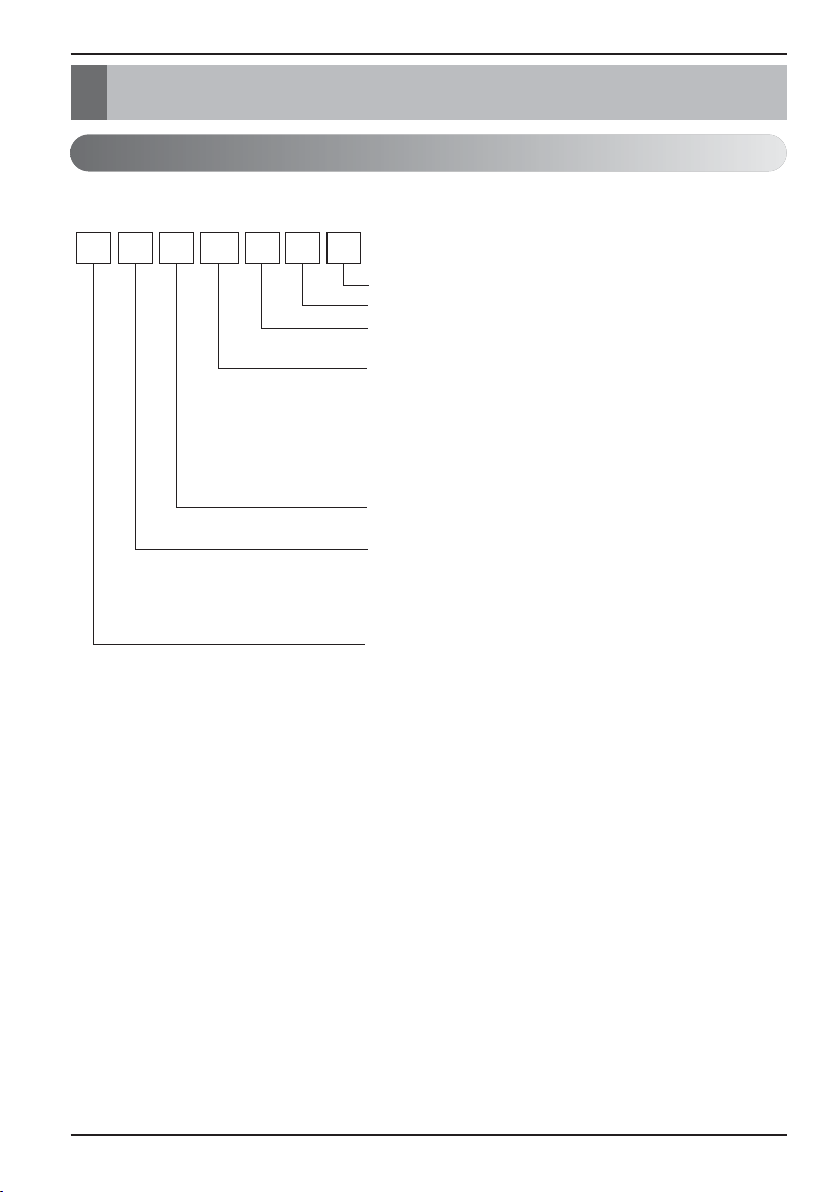
Model Designation
SM SQ15 BN 0
Serial number
Chassis name
Indoor Unit / Outdoor Units
N : Indoor Unit U : Outdoor Unit
Detailed product type only for M- series models
AQ : Wall mounted Libero-R SQ : Wall mounted Libero-E
AH* : ARTCOOL AW* : ART COOL Mirror
AH : Ceiling Cassette
AHL : Ceiling Concealed Duct (Low Static)
Detailed product type for U- / C- series models
L : Low Static H : High COP C : Econo
Nominal Capacity
Ex) 7 000 Btu/h Class → '07', 18 000 Btu/h Class → '18'
Product type
S : Wall mounted / ARTCOOL mirror J : Wall mounted
A : ARTCOOL T : Ceiling Cassette
B, M : Ceiling Concealed Duct V : Ceiling Suspended & floor
Q : Console P : Floor Standing
Connectable Outdoor unit type
M : Indoor units only for Multi systems
U : Indoor units only for Single A systems
C : Common Indoor Unit for Multi and Single CAC
Page 9

Model Designation
Installation Manual 9
ENGLISH
Limiting concentration is the limit of Freon gas concentration where immediate measures
can be taken without hurting human body when refrigerant leaks in the air. The limiting
concentration shall be described in the unit of kg/m
3
(Freon gas weight per unit air volume)
for facilitating calculation
n Calculate refrigerant concentration
Refrigerant
concentration (kg/m
3
)
Limiting concentration
The A-weighted sound pressure emitted by this product is below 70 dB.
** The noise level can vary depending on the site.
The figures quoted are emission level and are not necessarily safe working levels.
Whilst there is a correlation between the emission and exposure levels, this cannot be
used reliably to determine whether or not further precautions are required.
Factor that influence the actual level of exposure of the workforce include the
characteristics of the work room and the other sources of noise, i.e. the number of
equipment and other adjacent processes and the length of time for which an operator
exposed to the noise. Also, the permissible exposure level can vary from country to
country.
This information, however, will enable the user of the equipment to make a better
evaluation of the hazard and risk.
Total amount of replenished refrigerant in refrigerant facility (kg)
Capacity of smallest room where indoor unit is installed (m
3
)
Limiting concentration: 0.44 kg/m3(R410A)
=
Airborne Noise Emission
Page 10
10
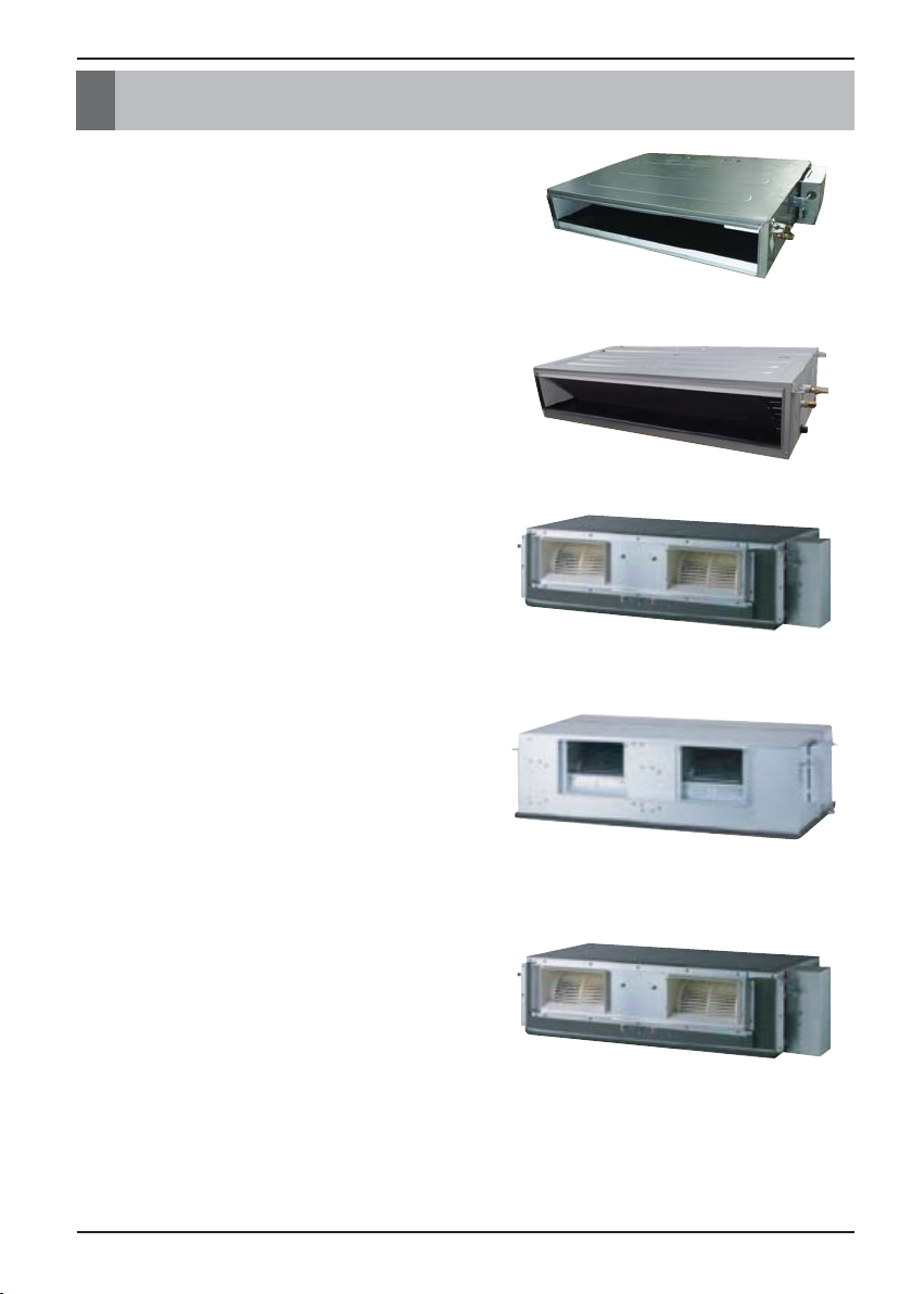
External Appearance
External Appearance
• Ceiling Concealed Duct – Low static pressure
L1/L2/L3 Chassis
• Ceiling Concealed Duct – Mid static pressure
M1/M2/M3 Chassis
• Ceiling Concealed Duct – H-INV
BR Chassis
• Ceiling Concealed Duct – Compact
BH Chassis
• Celling Concealed Duct – High static pressure
B8 Chassis
Page 11
Installation Places
Installation Manual 11
ENGLISH
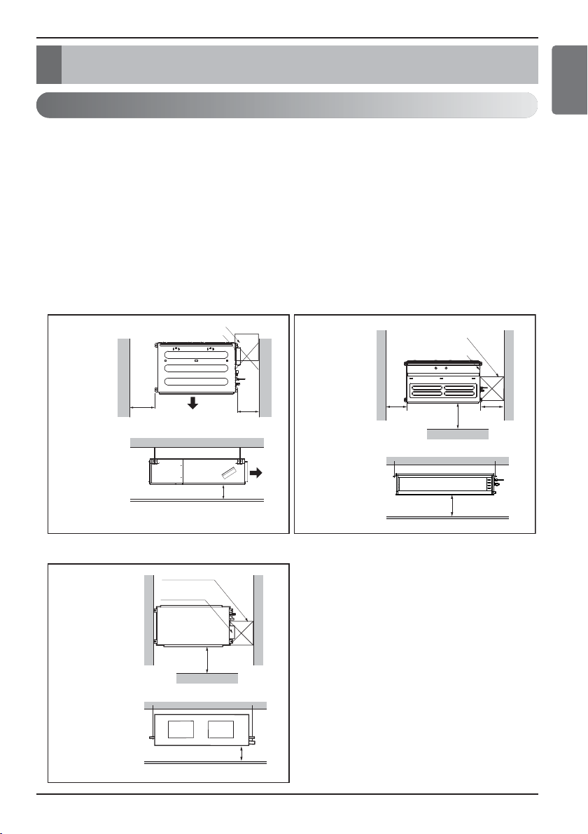
Ceiling Concealed Duct – Low Static Ceiling Concealed Duct – Mid Static
Ceiling Concealed Duct – Compact
Install the air conditioner in the location that satisfies the following conditions.
• The place shall easily bear a load exceeding four times the indoor unit’s weight.
• The place shall be able to inspect the unit as the figure.
• The place where the unit shall be leveled.
•
The place shall allow easy water drainage.
(Suitable dimension “H” is necessary to get a slope to drain as figure.)
• The place shall easily connect with the outdoor unit.
• The place where the unit is not affected by an electrical noise.
• The place where air circulation in the room will be good .
• There should not be any heat source or steam near the unit.
Inspection hole (600 x 600)
Control box
H=20 or more
• Suitable dimension "H" is necessary to get a slope
to drain as shown in the figure
600
600
Air outlet
Air outlet
Top view
(unit: mm)
Front view
Inspection hole
(600 x 600)
Control box
1 000
H
600
600
Front
Top view
(unit: mm)
(unit: mm)
Side view
Top view
(unit: mm)
Front view
H
Front
Inspection hole
(600 x 600)
Control box
1 000
Selection of the best location
Installation Places
Page 12
12
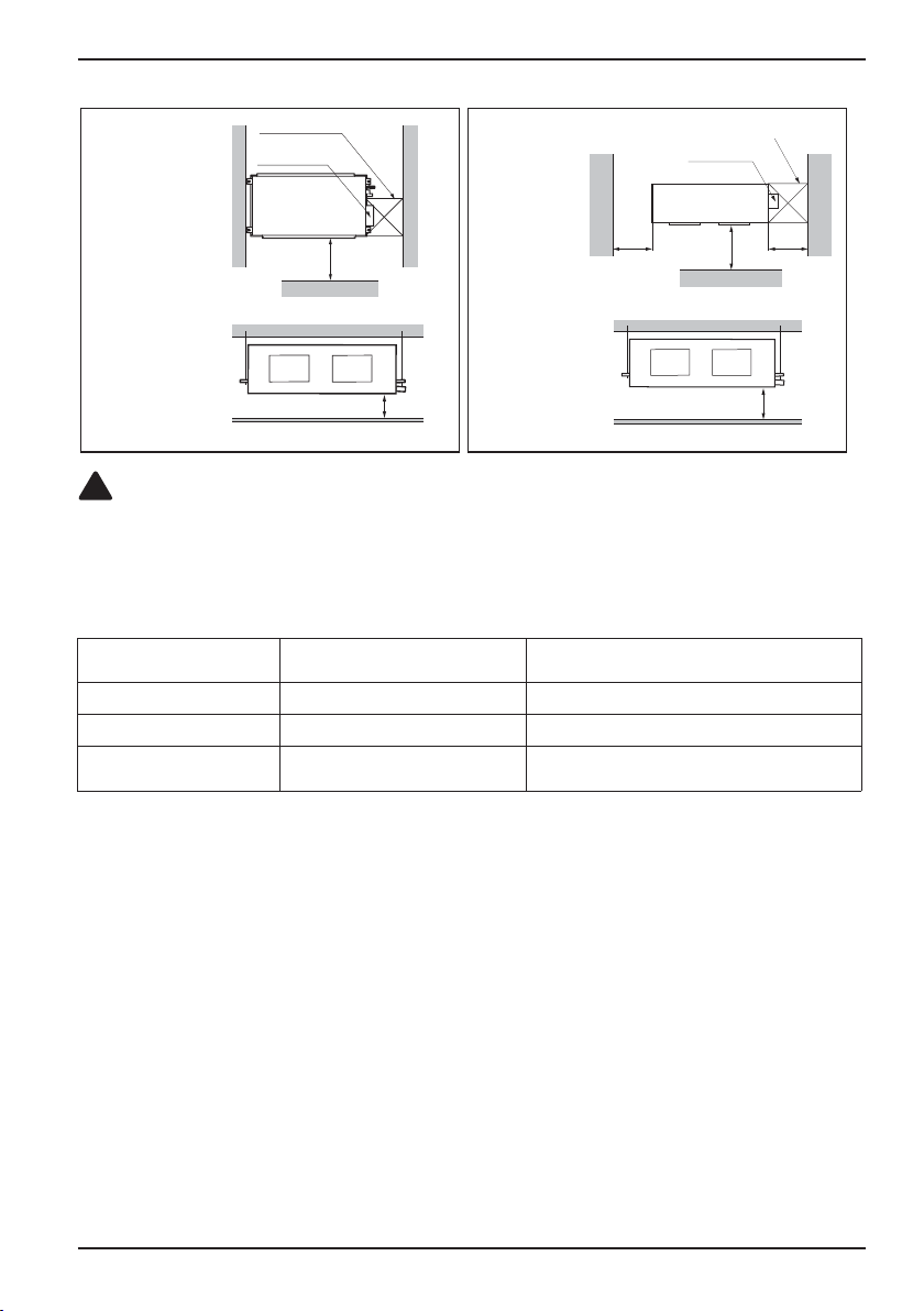
Installation Places
CAUTION
In case that the unit is installed near the sea, the installation parts may be corroded
by salt, The installation parts (and the unit) should be taken appropriate anti
corrosion measures.
!
[Inspection Hole Standard]
Number of
Inspection hole
Distance between
False ceiling & Actual ceiling
Remarks
1 More than 100 cm
Sufficient space in the ceiling for servicing.
2 20 cm to 100 cm
Insufficient space. Difficult for servicing
Hole size should be more
than the size of IDU.
Less than 20 cm
Minimum height for motor replacement.
Ceiling Concealed Duct – H-INV Ceiling Concealed Duct – High Static
Top view
(unit: mm)
Front view
Top view
(unit: mm)
Front view
H
Front
Inspection hole
(600 x 600)
Control box
1 000
H
600 600
Front
Inspection hole (600X600)
Control box
Page 13
The indoor unit installation
Installation Manual 13
ENGLISH
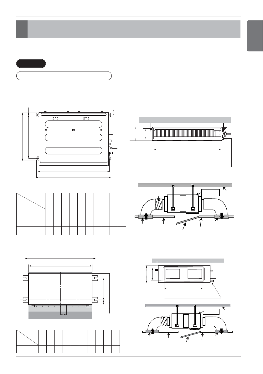
The indoor unit installation
Installation of Unit
Install the unit above the ceiling correctly.
CASE 1
POSITION OF SUSPENSION BOLT
• Apply a joint-canvas between the unit and duct to absorb unnecessary vibration.
• Apply a filter Accessory at air return hole.
C
E
G
D
F
I
A
J
B
H
Drainage hole
(Unit: mm)
Dimension
Capacity
(kBtu/h)
A B C D E F G H I J
9
733 772 628 700 36 190 20 660 155 700
12/18
933 972 628 700 36 190 20 860 155 900
24
1 133 1 172
628 700 36 190 20
1 060
155
1 100
Ceiling Concealed Duct – Low Static
Ceiling Concealed Duct – Compact
(Unit:mm)
A B C D E F (G) H I J
18/24 K
932 882 355 46 450 30 87 750 163 260
Dimension
Capacity
Inspection
Port
Indoor Unit
Ceiling
Canvas
Duct
Air Intake
Port
Ceiling
Board
Ceiling Board
Air Discharge
Port
Discharge
Flexible Duct
Intake
Duct
A
B
CD
(G)
EF
body
filter
Joint canvas
Main duct
Drainage hole
Inspection
Port
Indoor Unit
Ceiling
Canvas
Duct
Air Intake
Port
Ceiling
Board
Ceiling Board
Air Discharge
Port
Discharge
Flexible Duct
Intake
Duct
H
I
J
Page 14

14
The indoor unit installation
Drainage hole
C
E
G
D
F
I
A
J
B
H
Inspection
Port
Indoor Unit
Ceiling
Canvas
Duct
Air Intake
Port
Ceiling
Board
Ceiling Board
Air Discharge
Port
Discharge
Flexible Duct
Intake
Duct
Ceiling Concealed Duct – Mid Static
(Unit:mm)
ABCDEFGH I J
18 / 24 / 30
933.4 971.6 619.2 700 30 270 15.2 858 201.4 900
36 / 42
1 283.4 1 321.6
619.2 689.6 30 270 15.2
1 208
201.4
1 250
48 / 60
1 283.4 1 321.6
619.2 689.6 30 360 15.2
1 208
291.4
1 250
Dimension
Capacity
(kBtu/h)
Drainage hole
A
B
CD
(G)
EF
body
filter
Joint canvas
Main duct
H
I
J
Inspection
Port
Indoor Unit
Ceiling
Canvas
Duct
Air Intake
Port
Ceiling
Board
Ceiling Board
Air Discharge
Port
Discharge
Flexible Duct
Intake
Duct
Ceiling Concealed Duct – H-INV
(Unit:mm)
A B C D E F (G) H I J
36 / 42 / 46
1 290 1 230
447 56 590 30 120
1 006
294 380
Dimension
Capacity
(kBtu/h)
Page 15

The indoor unit installation
Installation Manual 15
ENGLISH
H
K
G
EF
L
I
J
B
A
C
D
Inspection
Port
Indoor Unit
Ceiling
Canvas
Duct
Air Intake
Port
Ceiling
Board
Ceiling Board
Air Discharge
Port
Discharge
Flexible Duct
Intake
Duct
Ceiling Concealed Duct – High Static
(Unit:mm)
Dimension
Capacity
(kBtu/h)
A B C D E F G H I J K L
70
85
1 594 1 044 286 460 580 713 1 368 1 622 392 458 1 563 791
CASE 2
• Install the unit leaning to a drainage hole
side as a figure for easy water drainage.
• A place where the unit will be leveled
and that can support the weight of the
unit.
• A place where the unit can withstand its
vibration.
• A place where service can be easily
performed.
POSITION OF CONSOLE BOLT
M10 Nut
M10 SP. washer
M10 washer
M10 washer
M10 SP. washer
M10 Nut
X 4
X 4
X 4
X 4
X 4
X 4
(Local
supply)
(Local
supply)
Page 16

16
Installation Places
CAUTION
Tighten the nut and bolt top revent unit falling.
!
• Select and mark the position for fixing
bolts.
• Drill the hole for set anchor on the face of
ceiling.
• Insert the set anchor and washer onto the
suspension bolts for locking the
suspension bolts on the ceiling.
• Mount the suspension bolts to the set
anchor firmly.
• Secure the installation plates onto the
suspension bolts (adjust level roughly)
using nuts, washers and spring washers.
• Local supply
① Set anchor
② Plate washer - M10
③ Spring washer - M10
④ Nut - W3/8 or M10
⑤ Suspension bolt - W3/8 or M10
Old building New building
1 Set anchor
2 Plate washer
3 Spring washer
4 Nut
5 Suspension
bolts
Page 17

The indoor unit installation
Installation Manual 17
ENGLISH
FRONT OF VIEW
• The unit must be horizontal or declined to the drain hose connected when finished
installation.
• The unit must be declined to the drain hose connected when finished installation.
Ceiling
Drain Pump use
Ceiling Concealed Duct – Low static
Drainage hole
Drainage hole
Drainage hole
CORRECT
INCORRECT
5~10 mm
Ceiling
Ceiling Concealed Duct – Mid static
Ceiling
Ceiling Concealed Duct – H-INV, Compact
H-INV :
5~10 mm
Compact : 1/100~1/50
Drainage hole
Drainage hole
CORRECT
INCORRECT
Ceiling
Ceiling Concealed Duct – High static
CORRECT
INCORRECT
Drainage hole
15 mm~25 mm
Drainage hole
CAUTION
!
1. Install declination of the indoor unit is very important for the drain of the duct type air
conditioner.
2. Minimum thickness of the insulation for the connecting pipe shall be 10mm.
Page 18

18
The indoor unit installation
CAUTION FOR GRADIENT OF
UNIT AND DRAIN PIPING
• Always lay the drain with downward
inclination.
Prevent any upward flow or reverse flow
in any part.
• 10 mm or thicker formed thermal insulator
shall always be provided for the drain
pipe.
• Upward routing not
CORRECT
• Install the P-Trap (or U-Trap) to prevent
a water leakage caused by the blocking
of intake air filter.
Lay the drain hose with a downward
inclination so water will drain out.
Thermal insulator
Unit
Make sure to be closed.
allowed
INCORRECT
Applied U-Trap Dimension
A
≥
70 mm
B
≥
2C
C ≥ 2 x SP
SP = External Pressure
(mmAq)
Ex) External Pressure
= 10 mmAq
A
≥
70 mm
B ≥ 40 mm
C ≥ 20 mm
Drainage hole
C
A
(Local supply)
Drainage pipe
(Local supply)
B
U-Trap
Page 19

The indoor unit installation
Installation Manual 19
ENGLISH
• Drain piping must have down-slope : be sure
not to provide up-and-down slope to prevent
reversal flow.
• During drain piping connection, be careful not
to exert extra force on the drain port on the
indoor unit.
• The outside diameter of the drain connection
on the indoor unit is 32 mm.
(Ceiling Concealed Duct – High static: 65 mm)
• Be sure to execute heat insulation on the drain
piping.
• Install the drain raising pipes at a right
angle to the indoor unit and no more than
300 mm from the unit.
Piping material: Polyvinyl chloride pipe VP-25
and pipe fittings
Heat insulation material: Polyethylene foam with thickness more than 10 mm.
• Connect the main drain pipe to the exterior and leave
it provisionally until the test comes to an end.
• Feed water to the flexible drain hose and check the
piping for leakage.
• When the test is complete, connect the flexible drain
hose to the drain port on the indoor unit.
Drain test
CAUTION
The supplied flexible drain hose should not be
curved, neither screwed. The curved or screwed
hose may cause a leakage of water.
!
1/50~1/100 slope
Hanger
distance
Hanger Bracket
Max 700 mm
Flexible drain hose
Insulation
Metal
clamp
Max 300 mm
1~15 m
Indoor Unit Drain Piping
Pipe clamp
Indoor unit
Maintenance
drain port
Upward
routing
not allowed
Feed water
Flexible drain hose
(accessory)
Main
drain pipe
Glue the joint
Page 20

20
The indoor unit installation
1) Remove the Air Filter.
2) Check the drainage.
• Spray one or two glasses of water upon the
evaporator.
• Ensure that water flows drain hose of indoor unit
without any leakage.
Page 21

The indoor unit installation
Installation Manual 21
ENGLISH
Be sure to give insulation work to refrigerant piping by covering liquid pipe and gas pipe separately
with enough thickness heat-resistant polyethylene, so that no gap is observed in the joint between
indoor unit and insulating material, and insulating materials themselves. When insulation work is
insufficient, there is a possibility of condensation drip, etc. Pay special attention to insulation work to
ceiling plenum.
Ⓐ Heat insulation material
Ⓑ Pipe
Ⓒ Outer covering(Wind the connection part
and cutting part of heat insulation material
with a finishing tape.)
Heat insulation
material
Adhesive + Heat - resistant
polyethylene foam + Adhesive tape
Outer
covering
Indoor Vinyl tape
Floor
exposed
Water-proof hemp cloth +
Bronze asphalt
Outdoor
Water-proof hemp cloth +
Zinc plate + Oily paint
Bad
example
• Do not insulate gas or low pressure pipe and liquid or high
pressurepipe together.
Liquid pipe
Gas pipe
Power cables
Finishing tape
Insulating material
Communication cables
• Be sure to fully insulate connecting portion.
These parts are not insulated.
Good
example
Liquid pipe
Communication cables
Communication cables
Separ
-ation
Gas pipe
Power cables
Insulating material
Power cables
Heat Insulation
Note :
When using polyethylene cover as
covering material, asphalt roofing shall not
be required.
Note :
Recommended Insulation material
Material : EPDM
Thickness : 15 mm(Gas pipe) and 19 mm(Liquid pipe) or over.
Density : less than 0.032 ±0.005(g/cm
2
)
Thermal conductivity : less than 0.03(kcal/m.hr.°C)
CAUTION
Cutting line of insulation must look upper direction. Thickness of insulation is 15 mm(Gas pipe) and
19 mm(Liquid pipe) or over.
!
Page 22

22
The indoor unit installation
Wiring Connection
• Open the control box cover and connect the Remote controller cord and Indoor power wires.
• Remove the control box cover for electrical connection between the indoor and outdoor
unit. (Remove screws ①.)
• Use the cord clamper to fix the cord.
Ceiling Concealed Duct – Low Static, Mid Static
Ceiling Concealed Duct – H-INV, Compact
Ceiling Concealed Duct – High static
CAUTION
!
Control terminal board
Control box
1
Control box cover
(On which the Electric
Wiring Connection is put)
1
Control box cover
(On which the Electric
1
Wiring Connection is put)
A
1
1
Control box cover
(On which the Electric
Wiring Connection is put)
Control box
Control terminal board
Remote controler cord
Connection cord between the indoor
unit and the outdoor unit
A
view
Remote
controler cord
Connection cord between the indoor
unit and the outdoor unit
Control terminal board
Connection cord between the indoor
unit and the outdoor unit
Remote controler cord
Control box
The connecting cable connected to the indoor and outdoor unit should be complied with the following
specifications (Rubber insulation, type H05RN-F approved by HAR or SAA).
GN/YL
If the supply cord is damaged, it must be replaced by a special cord or assembly available from the manufacturer of its service agent. When the
connection line between the indoor unit and outdooor unit and outdoor unit is over 40 m, connect the telecommunication line and power line separately.
NORMAL
CROSS-SECTIONAL
AREA 0.75 mm
20 mm
2
Page 23

The indoor unit installation
Installation Manual 23
ENGLISH
u Precautions when laying power wiring
Use round pressure terminals for connections to the power terminal block.
When none are available, follow the instructions below.
• Do not connect wiring of different thicknesses to the power terminal block. (Slack in the
power wiring may cause abnormal heat.)
• When connecting wiring which is the same thickness, do as shown in the figure below.
• For wiring, use the designated power wire and connect firmly, then secure to prevent
outside pressure being exerted on the terminal block.
• Use an appropriate screwdriver for tightening the terinal screws. A screwdriver with a
small head will strip the head and make proper tighterning impossible.
• Over-tightening the terminal screws may break them.
HAND OVER
Teach the customer the operation and maintenance procedures, using the operation manual.
(air filter cleaning, temperature control, etc.)
Round pressure terminal
Power wire
Page 24

24
Remote Controller Installation
Remote Controller Installation
1
2
3
2
3
<Wire guide grooves>
1. Please fix tightly using provided screw after placing
remote controller setup board on the place where you
like to setup.
- Please set it up not to bend because poor setup could take
place if setup board bends.
Please set up remote controller board fit to the reclamation
box if there is a reclamation box.
- Install the product so as not to make a gap with the wall
side and to prevent shaking after the installation.
2. Can set up Wired remote controller cable into three
directions.
- Setup direction: the surface of wall reclamation, upper, right
- If setting up remote controller cable into upper
and right side, please set up after removing
remote controller cable guide groove.
h
Remove guide groove with long nose.
①
Reclamation to the surface of the wall
②
Upper part guide groove
③
Right part guide groove
3. Please fix remote controller upper part into the setup
board attached to the surface of the wall, as the picture
below, and then, connect with setup board by pressing
lower part.
- Please connect not to make a gap at the remote controller
and setup board’s upper and lower, right and left part.
- Before assembly with the installation board, arrange the
Cable not to interfere with circuit parts.
When separating remote controller from setup board, as
the picture below, after inserting into the lower
separating hole using screw driver and then, spinning
clockwise, remote controller is separated.
- There are two separating holes. Please individually
separate one at a time.
- Please be careful not to damage the inside
components when separating.
Wall
Side
Wall
Side
Wall
Side
Wall
Side
<Connecting order>
<Separating order>
Page 25

Remote Controller Installation
Installation Manual 25
ENGLISH
Wired remote controller installation
Fig.1 Typical locations for remote controller
•
Since the room temperature sensor is in the remote controller, the remote controller box should be installed in a place
away from direct sunlight, high humidity and direct supply of cold air to maintain proper space temperature. Install the
remote controller about 5 ft(1.5 m) above the floor in an area with good air circulation at an average temperature.
Do not install the remote controller where it can be affected by:
- Drafts, or dead spots behind doors and in corners.
- Hot or cold air from ducts.
- Radiant heat from sun or appliances.
- Concealed pipes and chimneys.
- Uncontrolled areas such as an outside wall behind the remote controller.
- This remote controller is equipped with a seven segment LED. display. For proper display of the remote
controller LED's, the remote controller should be installed properly as shown in Fig.1.
(The standard height is 1.2~1.5 m from floor level.)
4. Please connect indoor unit and remote controller using connection cable.
5. Please use extension cable if the distance between wired remote controller and indoor unit is more
than 10 m.
Please check if connector is normally connected.
Connecting cable
Indoor
Unit side
CAUTION
When installing the wired remote controller, do not bury it in the wall. (It can cause damage in the
temperature sensor.)
Do not install the cable to be 50m or above. (It can cause communication error.)
• When installing the extension cable, check the connecting direction of the connector of the remote
controller side and the product side for correct installation.
• If you install the extension cable in the opposite direction, the connector will not be connected.
• Specification of extension cable: 2547 1007 22# 2 core 3 shield 5 or above.
!
12 V Red
Signal Yellow
GND Black
Direct
Sun ray contact area
no
no
yes
5 feet
(1.5 meters)
no
Page 26

26
Remote Controller Installation
OPERATION INDICATION SCREEN
SET TEMPERATURE BUTTON
FAN SPEED BUTTON
ON/OFF BUTTON
OPRATION MODE SELECTION BUTTON
WIRELESS REMOTE CONTROLLER
RECEIVER
• Some products don't receive the wireless
signals.
VENTILATION BUTTON
FUNCTION SETTING BUTTON
AIR FLOW BUTTON
SUBFUNCTION BUTTON
RESERVATION
UP,DOWN,LEFT,RIGHT BUTTON
• To check the indoor temperature, press
button.
ROOM TEMPERATURE BUTTON
SETTING/CANCEL BUTTON
EXIT BUTTON
1
2
3
4
5
6
7
8
9
10
11
12
13
14
15
Wired Remote Controller
j Some functions may not be operated and displayed depending on the product type.
h Display temperature can be different from actual room temperature if the remote controller is
installed at the place where sun-rays are falling directly or the place nearby heat source.
h The actual product can be different from above contents depending upon model type.
h When using simultaneous operation system, whenever press remote controller button, system will
approximately operate after 1~2 minutes.
1
10
9
8
7
11
12
13
14
15
Please attach the inform label inside of the door.
Please choose proper language depend on your
country.
2
3
4
5
6
NOTE
Page 27

Installation Manual 27
Optional Operation
ENGLISH
Installer Setting -Test Run Mode
After installing the product, you must run a Test Run mode.
For details related to this operation, refer to the product manual.
Optional Operation
If pressing button long for 3 seconds,
1
it enters into remote controller setter
setup mode.
- If pressing once shortly, it enters into
user setup mode. Please press more
than 3 seconds for sure.
- Please cancel the right and left of wind
direction for RAC product.
Function Code Set
Setup figure '01' blinks at the lower part
2
of indication window.
Press button to start.
3
During the test run, pressing the below
4
button will exit the test run.
- Select operation, temperature
up/down, wind flow control, wind
direction, start/stop button.
Page 28

28
Optional Operation
Installer Setting - Setting Address of Central Control
It's the function to use for connecting central control.
Please refer to central controller manual for the details
If pressing button long for 3
1
seconds, it enters into remote
controller setter setup mode.
- If pressing once shortly, it enters
into user setup mode. Please press
more than 3 seconds for sure.
If entering into address setup mode by using
2
button, it indicates as picture below.
Group No
Function Code
Set Group No. by pressing
3
button.(0~F)
Indoor No.
Move to Indoor No. setting option
4
by pressing button.
Set Indoor No. by pressing
5
button.
Press button to save.
6
Pressing button will exit settings mode.
7
❈ After setup, it automatically gets out of
setup mode if there is no button input for
25 seconds.
❈ When exiting without pressing set button,
the manipulated value is not reflected.
Page 29

Installation Manual 29
Optional Operation
ENGLISH
Installer Setting -Thermistor
j The function of 2TH has different operation characteristics according to the product.
<Thermistor Table>
This is the function to select the temperature sensor to judge the room temperature.
Temperature sensor selection
Function
01 Remote controller Operation in remote controller temperature sensor
02 Indoor unit Operation in indoor unit temperature sensor
03 2TH
Cooling
Operation of higher temperature by comparing indoor unit's and wired
remote controller’s temperature.
(There are products that operate at a lower temperature.)
Heating
Operation of lower temperature by comparing indoor unit's and wired
remote controller's temperature.
If pressing button long for 3
1
seconds, it enters into remote
controller setter setup mode.
- If pressing once shortly, it enters
into user setup mode. Please press
more than 3 seconds for sure.
If moving to room temperature perception
2
sensor selection menu by pressing
button, it indicates as picture below.
Set Thermistor value by pressing
3
button. (01: Remote Controller,
02: Indoor, 03: 2TH)
Function Code Thermistor setting
Press button to save.
4
Pressing button will exit settings mode.
5
❈ After setup, it automatically gets out of
setup mode if there is no button input for
25 seconds.
❈ When exiting without pressing set button,
the manipulated value is not reflected.
Page 30

30
Optional Operation
Installer Setting-Group Setting
It is a function for settings in group control, or 2-remote controller control.
Remote controller Function
Master
Indoor unit operates based on master remote controller at group control.
(Master is set when delivering from the warehouse.)
Slave
Setup all remote controllers except one master remote controller to slave
at group control
• When controlling in groups, basic operation settings, airflow strength weak/medium/strong,
lock setting of the remote controller, time settings, and other functions may be restricted.
h Refer to the 'group control' part for details
If pressing button long for 3
1
seconds, it enters into remote
controller setter setup mode.
- If pressing once shortly, it enters
into user setup mode. Please press
more than 3 seconds for sure.
If pressing button repeatedly, it moves to
2
master/slave selection menu as picture
below.
Select Master/ Slave by pressing
3
button.
(00: Slave, 01: Master)
Function Code Master/Slave value
Press button to save.
4
Pressing button will exit settings mode.
5
❈ After setup, it automatically gets out of
setup mode if there is no button input for
25 seconds.
❈ When exiting without pressing set button,
the manipulated value is not reflected.
Page 31

Installation Manual 31
ENGLISH
Optional Operation
Installer Setting-Dry Contact Mode Setting
Dry contact function is the function that is possible to use only when dry contact equipment is
separately purchased/setup.
▶
What is Dry Contact?
Like hotel card key and body perception sensor, it is the signal of the point of contact when
using air-conditioner by interlocking.
• Please refer to dry contact manual for more details.
If pressing button long for 3
1
seconds, it enters into remote
controller setter setup mode.
- If pressing once shortly, it enters
into user setup mode. Please press
more than 3 seconds for sure.
If pressing button repeatedly, it moves to
2
remote controller dry contact mode setup
menu as picture below.
Select Dry contact setting by
3
pressing button.
(00 : Automatic, 01 : manual)
Function Code Dry Contact
setting value
Press button to save.
4
Pressing button will exit settings mode.
5
❈ After setup, it automatically gets out of
setup mode if there is no button input for
25 seconds.
❈ When exiting without pressing set button,
the manipulated value is not reflected.
Page 32

32
Optional Operation
Installer Setting-Celsius / Fahrenheit Switching
This function is used for switching the display between Celsius and Fahrenheit.
(Optimized only for U.S.A)
h Whenever press button in Fahrenheit mode, the temperature will increase/drop 2
degrees.
If pressing button long for 3
1
seconds, it enters into remote
controller setter setup mode.
- If pressing once shortly, it
enters into user setup mode.
Please press more than 3 seconds for
sure.
Repeat pressing button to select
2
Function code 12.
Function Code
Ex) Fahrengeit Setting
Select Temperature unit mode by
3
pressing button.
(00: Celsius, 01: Fahrenheit)
Press button to save or release.
4
Press button to exit or
5
system will automatically exit
after 25 seconds without any
input.
conversion mode value
Page 33

Installation Manual 33
ENGLISH
Optional Operation
Installer Setting -Optional Function Setting
Setting feature for indoor unit when air cleaning / heater / humidifier / Up/down grill / Ventilation KIT
/ Auxiliary Heater is newly installed, or installed unit is removed.
If pressing button long for 3
1
seconds, it enters into remote
controller setter setup mode.
- If pressing once shortly, it enters
into user setup mode. Please press
more than 3 seconds for sure.
If pressing button repeatedly, it moves to
2
the selected option function code as picture
below.
Select existing condition
3
of each mode by pressing
button.
(00: not installed,
01 : installed)
Function
Plasma purification
Electric heater
Dehumidifier
Elevation grill
Ventilation kit
Auxiliary heater
Code
20
21
22
23
24
25
Function Code Existing condition
Press button to save.
4
Pressing button will exit settings mode.
5
❈ After setup, it automatically gets out of
setup mode if there is no button input for
25 seconds.
❈ When exiting without pressing set button,
the manipulated value is not reflected.
Page 34

34
Optional Operation
Installer Setting – Remote controller Mode Lock
This function is used to limit ‘operation-mode’ selection setting.
h It can limit only wired remote controller button. other controllers can change operation mode.
(for example wireless remote controller and central controller)
Press and hold button for
1
more than 3 seconds to enter
the installer settings mode.
Move to the installer code number 42 in the
2
menu using button.
Select the remote control master/slave using
3
button.
Code value for mode
lock setting
code Description
42:00
Doesn’t limit operation mode setting.
42:01
User can setting to cooling mode only.
42:02
User can setting to heating mode only.
Press button to save the setting.
4
Press button to exit.
5
Set value
Page 35

Installation Manual 35
ENGLISH
How to Set E.S.P?
• If you set ESP incorrectly, the air conditioner may malfunction.
• This setting must be carried out by a certificated-technician.
This is the function that decides the strength of the wind for each wind level and because this function
is to make the installation easier.
Installer Setting -E.S.P.
• When setting ESP value on the product without very weak wind or power wind function, it may not work.
• Please be careful not to change the ESP value for each fan step.
• It does not work to setup ESP value for very low/power step for some products.
• ESP value is available for specific range belongs to the product.
How to Set E.S.P?
ESP value
Function code,
ESP code
Move to ESP value setting by pressing
4
button.
(It is 000 when delivering
from the warehouse.)
If pressing button long for 3
1
seconds, it enters into remote
controller setter setup mode.
- If pressing once shortly, it enters
into user setup mode. Please press
more than 3 seconds for sure.
If entering into ESP setup mode by using
2
button, it indicates as the picture
below.
ESP step
Function Code ESP value
Select ESP fan step by
3
pressing button.
(01: very low, 02: low, 03:
medium, 04: high, 05:
very high)
Press button to setup ESP value.
5
(It is possible to setup ESP
value from 1 to 255, and 1 is
the smallest and 255 is the
biggest.)
Select ESP fan step again by using
6
button and setup ESP value, as No.
4 and 5, that corresponds each wind flow
Press button to save.
7
Press button to exit.
8
❈ After setup, it automatically gets out of
setup mode if there is no button input
for 25 seconds.
❈ When exiting without pressing set
button, the manipulated value is not
reflected.
Page 36

36
How to Set E.S.P?
Installer Setting - Static Pressure Step Setting
- Static Pressure (Code 06) setting will not be used if Static Pressure Step (Code 32)
setting is being used.
- For the static pressure value for each step, refer to the next page Table. 1
This function is applied to only duct type. Setting this in other cases will cause malfunction.
This function is only available on some products.
This is the function that static pressure of the product is divided in 11 steps for setting.
When pressing the button and
1
button simultaneously for more than 3
seconds, the system will be entered into the
installer setting mode.
- After entering into the installer setting
mode, select the static pressure step
setting code value by pressing the
button.
* Static pressure step setting code value : 32
Select the desired setting value with the
2
temperature up(
ƞ
), down(Ơ) button.
Function Code
00: use static pressure (code 06) set value
01~ 11: static pressure step (code 32) set value
When pressing button, currently
3
established static pressure value will be set
up.
When pressing the button and button
4
simultaneously for more than 3 seconds after
the setting has been completed, the setting
mode will be released.
- If there isn’t any button input for more than
25 seconds, the installer setting mode will
also be released.
Existing condition
Page 37

Installation Manual 37
ENGLISH
How to Set E.S.P?
Note :
1. The above table shows the correlation between the air rates and E.S.P.
2. Be sure to set the value refering table 1. Unexpected set value will cause mal-function.
3. Table 1 is based at 230 V. According to the fluctuation of voltage, air flow rate varies.
Ceiling Concealed Duct – Low static
Table 1
Model Step CMM
Static Pressure [mmAq (Pa)]
0(0) 1(10) 2(20) 3(29) 4(39) 5(49)
Setting Value
32:01 32:02 32:03 32:04 32:05 32:06
CB09L.N12
LOW 5.5 69 76 83 91 101 111
MID 7 81 87 94 101 109 117
HIGH 9 97 103 108 117 124 131
Model Step CMM
Static Pressure [mmAq (Pa)]
0(0) 1(10) 2(20) 3(29) 4(39) 5(49)
Setting Value
32:01 32:02 32:03 32:04 32:05 32:06
CB12L.N22
LOW 7 78 82 87 93 100 107
MID 8.5 87 91 94 100 108 116
HIGH 10 96 100 103 109 117 125
Model Step CMM
Static Pressure [mmAq (Pa)]
0(0) 1(10) 2(20) 3(29) 4(39) 5(49)
Setting Value
32:01 32:02 32:03 32:04 32:05 32:06
CB18L.N22
LOW 10 96 100 103 109 117 125
MID 12.5 109 113 117 123 130 137
HIGH 15 120 124 129 134 141 147
Model Step CMM
Static Pressure [mmAq (Pa)]
0(0) 1(10) 2(20) 3(29) 4(39) 5(49)
Setting Value
32:01 32:02 32:03 32:04 32:05 32:06
CB24L.N32
LOW 12 89 95 102 106 120 130
MID 16 102 108 115 125 131 139
HIGH 20 125 131 136 141 144 147
Page 38

38
How to Set E.S.P?
Ceiling Concealed Duct – Mid static
Table 2
Model Step CMM
Static Pressure[mmAq(Pa)]
2(20) 2.5(25) 3(29) 4(39) 6(59) 8(78) 10(98) 12(118) 13(127)14(137) 15(147)
Setting Value
32:01 32:02 32:03 32:04 32:05 32:06 32:07 32:08 32:09 32:10 32:11
CM18.N14
LOW 13 73 74 77 88 93 103 111
117
120 125 128
MID 14.5 76 77 85 91 97 107 114 121 125 128 131
HIGH 16.5 85 87 90 94 103 110
118
125 128 131 134
CM24.N14
LOW 14.5 76 77 85 89 97 107 114 121 125 128 131
MID 16.5 85 87 90 94 103 110 118 125 128 131 134
HIGH 18 90 92 95 99 108 115 122 129 132 135 138
Model Step CMM
Static Pressure[mmAq(Pa)]
4(39) 5(49) 6(59) 7(69) 8(78) 9(88) 10(98) 11(108) 12(118) 13(127)15(147)
Setting Value
32:01 32:02 32:03 32:04 32:05 32:06 32:07 32:08 32:09 32:10 32:11
UM36.N24
LOW 24 88 91 95 100 101 108 113 115 118 121 128
MID 28
93 97 101 105 108 115 118 120 124 127 134
HIGH 32 101 105 109 112 115 119 123 126 128 133 137
Model Step CMM
Static Pressure[mmAq(Pa)]
4(39) 5(49) 6(59) 7(69) 8(78) 9(88) 10(98) 11(108) 12(118) 13(127)15(147)
Setting Value
32:01 32:02 32:03 32:04 32:05 32:06 32:07 32:08 32:09 32:10 32:11
UM48.N34
LOW
MID
HIGH
Model Step CMM
Static Pressure[mmAq(Pa)]
5(49) 6(59) 7(69) 8(78) 9(88) 10(98) 11(108) 12(118) 13(127) 14(137) 15(147)
Setting Value
32:01 32:02 32:03 32:04 32:05 32:06 32:07 32:08 32:09 32:10 32:11
UM42.N24
LOW 28 100 103 106 110 114
118
121 125 128 133 136
MID 33 108 111 114 118 122 125 128 131 134 138 141
HIGH 38 117 120 124 127 130 133 135 138 141 144 147
Model Step CMM
Static Pressure[mmAq(Pa)]
2.5(25) 4(39) 5(49) 6(59) 7(69) 8(78) 9(88) 10(98) 11(108) 13(127) 15(147)
Setting Value
32:01 32:02 32:03 32:04 32:05 32:06 32:07 32:08 32:09 32:10 32:11
UM30.N14
LOW 18 96 102 107 110 114 118 122 125 127 132 134
MID 20 102 110 114 118 121 125
127
130 133 135 137
HIGH 22 110 117 121 124 127 130 133 136 137 138 140
28 74 76 79 82 89 92 94 96 99 102 107
34 78 82 84 89 94 96 98 101 104 106 112
40 83 89 92 94 98 100 102 105 108 110 116
Model Step CMM
Static Pressure[mmAq(Pa)]
4(39) 5(49) 6(59) 7(69) 8(78) 9(88) 10(98) 11(108) 12(118) 13(127)15(147)
Setting Value
32:01 32:02 32:03 32:04 32:05 32:06 32:07 32:08 32:09 32:10 32:11
UM60.N34
LOW
MID
HIGH
40 82 89 92 94 98 100 102 105 108 110 113
45 90 92 96 98 102 104 106 109 112 114 117
50 94 97 100 104 107 109 112 115 117 119 121
Page 39

How to Set E.S.P?
Installation Manual 39
ENGLISH
NOTE
1. Be sure to set the value refering table 2. Unexpected set value will cause mal-function.
2. Table 2 is based at 230 V. According to the fluctuation of voltage, air flow rate varies.
3. Factory Set(External Static Pressure) each Model
* If it is zero static pressure, please set value below Maximum value.
Model Maximum value
CM18.N14
115
CM24.N14
UM30.N14
120UM36.N24
UM42.N24
UM48.N34
98
UM60.N34
Model Factory set (E.S.P.) mmAq(Pa)
CM18.N14
6(59)
CM24.N14
UM30.N14
UM36.N24
UM42.N24
UM48.N34
UM60.N34
Page 40

40
How to Set E.S.P?
Ceiling Concealed Duct – H-INV
Table 3
Model Step CMM
Static Pressure [mmAq (Pa)]
4(39) 5(49) 6(59) 8(78) 10(98) 12(118)
Setting Value
32:01 32:02 32:03 32:04 32:05 32:06
UB36H.NR3
LOW 21 68 72 78 84 91 97
MID 28 75 79 84 89 95 101
HIGH 34 81 85 88 94 100 105
Model Step CMM
Static Pressure [mmAq (Pa)]
4(39) 5(49) 6(59) 8(78) 10(98) 12(118)
Setting Value
32:01 32:02 32:03 32:04 32:05 32:06
UB42H.NR3
LOW 24 75 79 86 93 98
MID 31 81 85 91 98 103
HIGH 37 88 91 97 102 107
Model Step CMM
Static Pressure [mmAq (Pa)]
4(39) 5(49) 6(59) 8(78) 10(98) 12(118)
Setting Value
32:01 32:02 32:03 32:04 32:05 32:06
UB48H.NR3
LOW 28 79 84 89 95 101
MID 34 85 88 94 100 105
HIGH 40 91 93 99 105 110
NOTE
Be sure to set the value referring table 3. Unexpected set value will cause mal-function.
As far as possible do not set ESP 82,83
Table 3 is based at 230 V. According to the fluctuation of voltage, air flow rate varies.
Page 41

How to Set E.S.P?
Installation Manual 41
ENGLISH
Model Step CMM
Static Pressure[mmAq(Pa)]
6(59) 7(69) 8(78) 9(88) 10(98) 12(118) 13(127) 14(137) 15(147) 16(157) 18(176)
Setting Value
32:01 32:02 32:03 32:04 32:05 32:06 32:07 32:08 32:09 32:10 32:11
UB70.N94
LOW 60 70 72 74 76 78 81 82 85 86 88 91
MID 65 74 76 78 80 82 85 86 89 90 92 95
HIGH 70 78 80 82 84 86 90 91 93 94 96 99
Model Step CMM
Static Pressure[mmAq(Pa)]
6(59) 7(69) 8(78) 9(88) 10(98) 12(118) 13(127) 14(137) 15(147) 16(157) 18(176)
Setting Value
32:01 32:02 32:03 32:04 32:05 32:06 32:07 32:08 32:09 32:10 32:11
UB85.N94
LOW 64 74 75 76 78 79 82 84 86 89 91 95
MID 72 78 79 80 82 83 87 89 91 94 96 100
HIGH 80 82 84 86 88 90 93 95 97 100 101 105
Ceiling Concealed Duct – High static
Table 4
NOTE
1. Be sure to set the value refering table 4. Unexpected set value will cause mal-function.
2. Table 4 is based at 230V. According to the fluctuation of voltage, air flow rate varies.
3. Factory Set(External Static Pressure) each Model
* If it is zero static pressure, please set value below Maximum value.
Model Maximum value
UB85.N94
UB70.N94
105
Model Factory set (E.S.P.) mmAq(Pa)
UB85.N94
UB70.N94
13 (127)
Capacity Step C.M.M
Static Pressure(mmAq)
2.5456810
Setting Value
18 k
HIGH 13.5 102 112 119 125 - -
MID 12 96 106 114 119 - -
LOW 10.5 90 102 108 114 - -
24 k
HIGH 18 121 131 137 142 - -
MID 16.5 115 125 130 135 - -
LOW 14 106 116 121 125 - -
Ceiling Concealed Duct – Compact
Table 5
Page 42

42
Self-diagnosis Function
Indoor Unit Error
Ex) Error 03 (Remote controller error)
Dip Switch Setting
Indoor PCB
Function Description Setting Off Setting On Default
SW3 Group Control Selection of Master or Slave Master Slave Off
SW4 Dry Contact Mode
Selection of Dry Contact
Mode
Wired/Wireless remote
controller
Selection of Manual or Auto
operation Mode
Auto Off
SW5 Installation Fan continuous operation
Continuous operation
Removal
Working Off
01 Indoor Room sensor error 0 1 time ◑ OFF
02 Indoor in-pipe sensor error 0 2 times ◑ OFF
03 Remote controller error 0 3 times ◑ OFF
04 Drain pump error 0 4 times ◑ OFF
05 Communication error indoor and outdoor 0 5 times ◑ OFF
06 Indoor out-pipe sensor error 0 6 times ◑ OFF
09 EEPROM error (indoor) 0 9 times ◑ OFF
10 BLDC motor fan lock (indoor) 1 time ◑ 0 OFF
Error Code
Description
LED 1
(Red)
LED 2
(Green)
Indoor
status
h Because remote controller turn off when occur ERROR in simultaneous operation system, it
should check LED blinks of outdoor in order to confirm error code.
h Repeatedly after LED1 is turned on and off as the Error code number of tens digit, LED2 is
turned on and off as the Error code number of single-digit.
Self-diagnosis Function
3 Times 3 Times 3 Times
LED02G
(GREEN)
2 s
2 s
Indoor PCB
Indoor PCB
Page 43

 Loading...