

Page 1
Internal Use Only
Website http://biz.lgservice.com
MODEL: BH7420PWN (BH7420PWN, S72T1-S/W, S72B1-S/C, T2, W2)SERVICE MANUAL
TM
3D Blu-ray
/ DVD
HOME CINEMA SYSTEM
SERVICE MANUAL
MODEL: BH7420PWN
CAUTION
BEFORE SERVICING THE UNIT, READ THE “SAFETY PRECAUTIONS”
IN THIS MANUAL.
(BH7420PWN, S72T1-S/W, S72B1-S/C, T2, W2)
P/NO : AFN75741181 APRIL, 2012
Page 2

CONTENTS
SECTION 1 ........ SUMMARY
SECTION 2 ........ ELECTRICAL
SECTION 3 ........ CABINET & MAIN CHASSIS
SECTION 4 ........ MT8560 F/E LOADER PART
SECTION 5 ........ WIRELESS RECEIVER PART
SECTION 6 ........ REPLACEMENT PARTS LIST
1-1
Page 3

SECTION 1
SUMMARY
CONTENTS
PRODUCT SAFETY SERVICING GUIDELINES FOR BD-HTS PRODUCTS .................................................. 1-3
SERVICING PRECAUTIONS ............................................................................................................................ 1-4
• GENERAL SERVICING PRECAUTIONS
• INSULATION CHECKING PRODEDURE
• ELECTROSTATICALLY SENSITIVE (ES) DEVICES
INITIAL SYSTEM SETUP .................................................................................................................................. 1-5
HIDDEN KEY MODE ......................................................................................................................................... 1-6
SOFTWARE UPGRADE .................................................................................................................................... 1-7
NETWORK UPDATE ......................................................................................................................................... 1-8
SPECIFICATIONS ........................................................................................................................................... 1-10
1-2
Page 4
PRODUCT SAFETY SERVICING GUIDELINES FOR BD-HTS PRODUCTS
IMPORTANT SAFETY NOTICE
This manual was prepared for use only by properly trained audio-video service
technicians.
When servicing this product, under no circumstances should the original design be
modified or altered without permission from LG Corporation. All components should
be replaced only with types identical to those in the original circuit and their physical
location, wiring and lead dress must conform to original layout upon completion of
repairs.
Special components are also used to prevent x-radiation, shock and fire hazard.
These components are indicated by the letter “x” included in their component designators and are required to maintain safe performance. No deviations are allowed
without prior approval by LG Corporation.
Circuit diagrams may occasionally differ from the actual circuit used. This way,
implementation of the latest safety and performance improvement changes into the
set is not delayed until the new service literature is printed.
CAUTION : Do not attempt to modify this product in any way. Never perform cus-
tomized installations without manufacturer’s approval. Unauthorized modifications
will not only void the warranty, but may lead to property damage or user injury.
Service work should be performed only after you are thoroughly familiar with these
safety checks and servicing guidelines.
GRAPHIC SYMBOLS
The exclamation point within an equilateral triangle is intended to
alert the service personnel to important safety information in the
service literature.
The lightning flash with arrowhead symbol within an equilateral
triangle is intended to alert the service personnel to the presence of
noninsulated “dangerous voltage” that may be of sufficient magnitude
to constitute a risk of electric shock.
The pictorial representation of a fuse and its rating within an equilateral triangle is intended to convey to the service personnel the
following fuse replacement caution notice:
CAUTION : FOR CONTINUED PROTECTION AGAINST RISK
OF FIRE, REPLACE ALL FUSES WITH THE SAME TYPE AND
RATING AS MARKED NEAR EACH FUSE.
SERVICE INFORMATION
While servicing, use an isolation transformer for protection from AC line shock. After
the original service problem has been corrected, make a check of the following:
FIRE AND SHOCK HAZARD
1. Be sure that all components are positioned to avoid a possibility of adjacent
component shorts. This is especially important on items trans-ported to and from
the repair shop.
2. Verify that all protective devices such as insulators, barriers, covers, shields,
strain reliefs, power supply cords, and other hardware have been reinstalled per
the original design. Be sure that the safety purpose of the polarized line plug has
not been defeated.
3. Soldering must be inspected to discover possible cold solder joints, solder
splashes, or sharp solder points. Be certain to remove all loose foreign particles.
4. Check for physical evidence of damage or deterioration to parts and components, for frayed leads or damaged insulation (including the AC cord), and
replace if necessary.
5. No lead or component should touch a high current device or a resistor rated at 1
watt or more. Lead tension around protruding metal surfaces must be avoided.
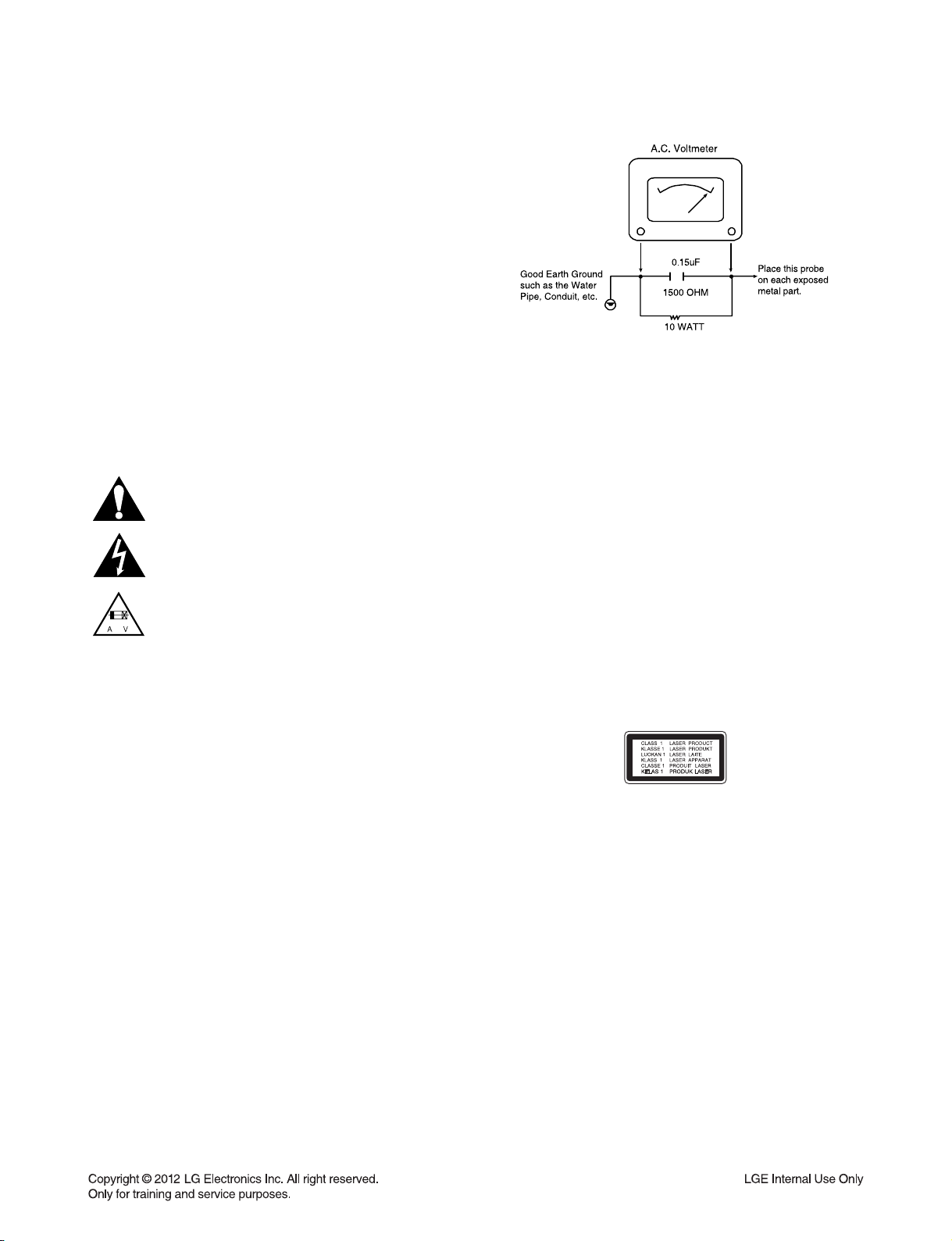
6. After reassembly of the set, always perform an AC leakage test on all exposed
metallic parts of the cabinet (the channel selector knobs, antenna terminals,
handle and screws) to be sure that set is safe to operate without danger of
electrical shock. DO NOT USE A LINE ISOLATION TRANSFORMER DURING
THIS TEST. Use an AC voltmeter having 5000 ohms per volt or more sensitivity
in the following manner: Connect a 1500 ohm, 10 watt resistor, paralleled by a
.15 mfd 150V AC type capacitor between a known good earth ground water pipe,
conduit, etc.) and the exposed metallic parts, one at a time. Measure the AC voltage across the combination of 1500 ohm resistor and .15 mfd capacitor. Reverse
the AC plug by using a non-polarized adaptor and repeat AC voltage measurements for each exposed metallic part. Voltage measured must not exceed 0.75
volts RMS. This corresponds to 0.5 milliamp AC. Any value exceeding this limit
constitutes a potential shock hazard and must be corrected immediately.
TIPS ON PROPER INSTALLATION
1. Never install any receiver in a closed-in recess, cubbyhole, or closely fitting shelf
space over, or close to, a heat duct, or in the path of heated air flow.
2. Avoid conditions of high humidity such as: outdoor patio installations where dew
is a factor, near steam radiators where steam leakage is a factor, etc.
3. Avoid placement where draperies may obstruct venting. The customer should
also avoid the use of decorative scarves or other coverings that might obstruct
ventilation.
4. Wall- and shelf-mounted installations using a commercial mounting kit must
follow the factory-approved mounting instructions. A product mounted to a shelf
or platform must retain its original feet (or the equivalent thickness in spacers) to
provide adequate air flow across the bottom. Bolts or screws used for fasteners
must not touch any parts or wiring. Perform leakage tests on customized installations.
5. Caution customers against mounting a product on a sloping shelf or in a tilted
position, unless the receiver is properly secured.
6. A product on a roll-about cart should be stable in its mounting to the cart.
Caution the customer on the hazards of trying to roll a cart with small casters
across thresholds or deep pile carpets.
7. Caution customers against using extension cords. Explain that a forest of extensions, sprouting from a single outlet, can lead to disastrous consequences to
home and family.
CAUTION : CLASS 1M VISIBLE AND INVISIBLE LASER
RADIATION WHEN OPEN. DO NOT VIEW DIRECTLY WITH
OPTICAL INSTRUMENTS
Use of controls, adjustments or the performance of procedures
other than those specified herein may result in hazardous radiation exposure.
1-3
Page 5

SERVICING PRECAUTIONS
CAUTION: Before servicing the BD-HTS covered by this service data and its supplements and addends, read and follow
the SAFETY PRECAUTIONS.
NOTE: if unforeseen circumstances create conflict between
the following servicing precautions and any of the safety
precautions in this publications, always follow the safety precautions.
Remember Safety First :
General Servicing Precautions
1. Always unplug the BD-HTS AC power cord from the AC
power source before:
(1) Removing or reinstalling any component, circuit board,
module, or any other assembly.
(2) Disconnecting or reconnecting any internal electrical
plug or other electrical connection.
(3) Connecting a test substitute in parallel with an electro-
lytic capacitor.
Caution : A wrong part substitution or incorrect polar-
ity installation of electrolytic capacitors may result in an
explosion hazard.
2. Do not spray chemicals on or near this BD-HTS or any of its
assemblies.
Electrostatically Sensitive (ES) Devices
Some semiconductor (solid state) devices can be damaged
easily by static electricity. Such components commonly are
called Electrostatically Sensitive (ES) Devices. Examples of
typical ES devices are integrated circuits and some field effect
transistors and semiconductor chip components.
The following techniques should be used to help reduce the
incidence of component damage caused by static electricity.
1. Immediately before handling any semiconductor component or semiconductor-equipped assembly, drain off any
electrostatic charge on your body by touching a known
earth ground. Alternatively, obtain and wear a commercially
available discharging wrist strap device, which should be
removed for potential shock reasons prior to applying power
to the unit under test.
2. After removing an electrical assembly equipped with ES
devices, place the assembly on a conductive surface such
as aluminum foil, to prevent electrostatic charge buildup or
exposure of the assembly.
3. Use only a grounded-tip soldering iron to solder or unsolder
ES devices.
3. Unless specified otherwise in this service data, clean electrical contacts by applying an appropriate contact cleaning
solution to the contacts with a pipe cleaner, cotton-tipped
swab, or comparable soft applicator.
Unless specified otherwise in this service data, lubrication of
contacts is not required.
4. Do not defeat any plug/socket B+ voltage interlocks with
whitch instruments covered by this service manual might be
equipped.
5. Do not apply AC power to this BD-HTS and / or any of its
electrical assemblies unless all solidstate device heat sinks
are correctly installed.
6. Always connect the test instrument ground lead to an
appropriate ground before connecting the test instrument
positive lead. Always remove the test instrument ground
lead last.
Insulation Checking Procedure
Disconnect the attachment plug from the AC outlet and turn
the power on. Connect an insulation resistance meter (500V)
to the blades of the attachment plug. The insulation resistance
between each blade of the attachment plug and accessible
conductive parts (Note 1) should be more than 1Mohm.
Note 1 : Accessible Conductive Parts include Metal panels,
Input terminals, Earphone jacks,etc.
4. Use only an anti-static solder removal device. Some solder
removal devices not classified as “anti-static” can generate
electrical charges sufficient to damage ES devices.
5. Do not use freon-propelled chemicals. These can generate
an electrical charge sufficient to damage ES devices.
6. Do not remove a replacement ES device from its protective
package until immediately before you are ready to install
it. (Most replacement ES devices are packaged with leads
electrically shorted together by conductive foam, aluminum
foil,or comparable conductive material).
7. Immediately before removing the protective material from
the leads of a replacement ES device, touch the protective
material to the chassis or circuit assembly into which the
device will be installed.
Caution: Be sure no power is applied to the chassis or cir-
cuit, and observe all other safety precautions.
8. Minimize bodily motions when handling unpackaged
replacement ES devices. (Normally harmless motion such
as the brushing together of your clothes fabric or the lifting
of your foot from a carpeted floor can generate static electricity sufficient to damage an ES device.)
1-4
Page 6
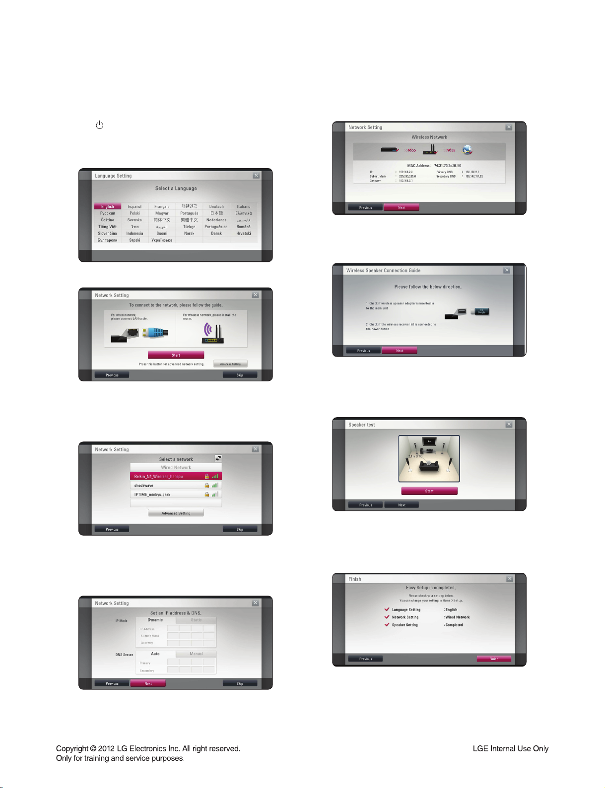
INITIAL SYSTEM SETUP
When you turn on the unit for the fi rst time, the initial setup wizard appears on the screen. Set the display language,
network setting and speaker setup on the initial setup wizard.
1. Press (POWER).
The initial setup wizard appears on the screen.
2. Use c/d/e/f to select a display language and
press ENTER (~).
Network connection status is displayed on the screen.
For details on network settings, refer to O/M for “Connecting to your Home Network”.
7. Select [Next] and press ENTER (~).
3. Read and prepare the preparations for the network set-
tings and then press ENTER (~) while [Start] is highlighted.
If wired network is connected , the network connection
setting will automatically be fi nished.
4. All available networks are displayed on the screen.
Use c/d to select [Wired Network] or desired SSID of
wireless network and press ENTER (~).
If you have security on your access point, you need to
input the security code as necessary.
5.
Use c/d/e/f to select the IP mode between
[Dynamic] and [Static]. Normally, select [Dynamic]
to allocate an IP address automatically
Read and prepare the preparations for the wireless
speaker setting.
8. Select [Next] and press ENTER (~).
9. Press ENTER (~) to verify the test tone signals of
the speakers.
After verifying the test tone signals, press ENTER (~)
while [Stop] is highlighted. Select [Next] and press ENTER (~).
10. Check all the settings that you have set in the previous steps.
6. Select [Next] and press ENTER (~) to apply network
settings.
Press ENTER (~) while [Finish] is highlighted to fi n-
ish the initial setup settings. If there is any settings to
be changed, use e/f to select [Previous] and press
ENTER (~).
1-5
Page 7

HIDDEN KEY MODE
HIDDEN
MODE
DISPLAY
SYSTEM
INFORMATION
DISPLAY
DEBUG
INFORMATION
EEPROM
INITIAL
DOOR
LOCK
WIRELESS
SPK
REMATE
AVAILABLE
STATUS
(NO DISC || OPEN)
&& (Highlight on
16:9 Full of setup
menu)
(NO DISC || OPEN)
&& (Highlight on
16:9 Full of setup
menu)
POWER ON
STATUS
DVD FUNCTION
and POWER ON
STATUS
POWER ON
STATUS
ENTRANCE
KEY
1+3+9+7+1+3+9+
ENTER or MP2
4+5+6+2+5+8+0+
ENTER
Front ‘STOP’ +
RMC ‘0’ for 5s
Front ‘STOP’ +
RMC ‘STOP’ for 5s
Front ‘STOP’ +
RMC ‘MUTE’
EXIT
KEY
PAUSE or HOME
※ ‘Pause’ Key
FACTORY RESET
RETURN/PAUSE
Auto exit “E2P CLEAR”
Toggling
- “REMATE”
INFORMATION
(KEY,VERSION)
1. PLATFORM
INFORMATION
2. HDMI
CONNECTTON
INFORMATION
3. WIRELESS
INFORMATION
“Locked” display
DISPLAY
SYSTEM
for 3s
1-6
Page 8
SOFTWARE UPGRADE
• Burn a DVD recordable disc or USB with a file that is named to “LG_HB_7000M60.ROM”.
• Insert a upgrading disc or USB.
• Show help message for disc upgrade as follows.
Press Enter key to upgrade.
Press Enter key to upgrade and it will show progress information.
After completing upgrade then power is off.
1-7
Page 9
NETWORK UPDATE
You can update the fi rmware by connecting your unit device directly to the S/W update server.
Confi guring Network Settings
To update the fi rmware by connecting your player directly to the S/W update server, your player must be
connected to network. If your player is not connected to network, make a physical connection.
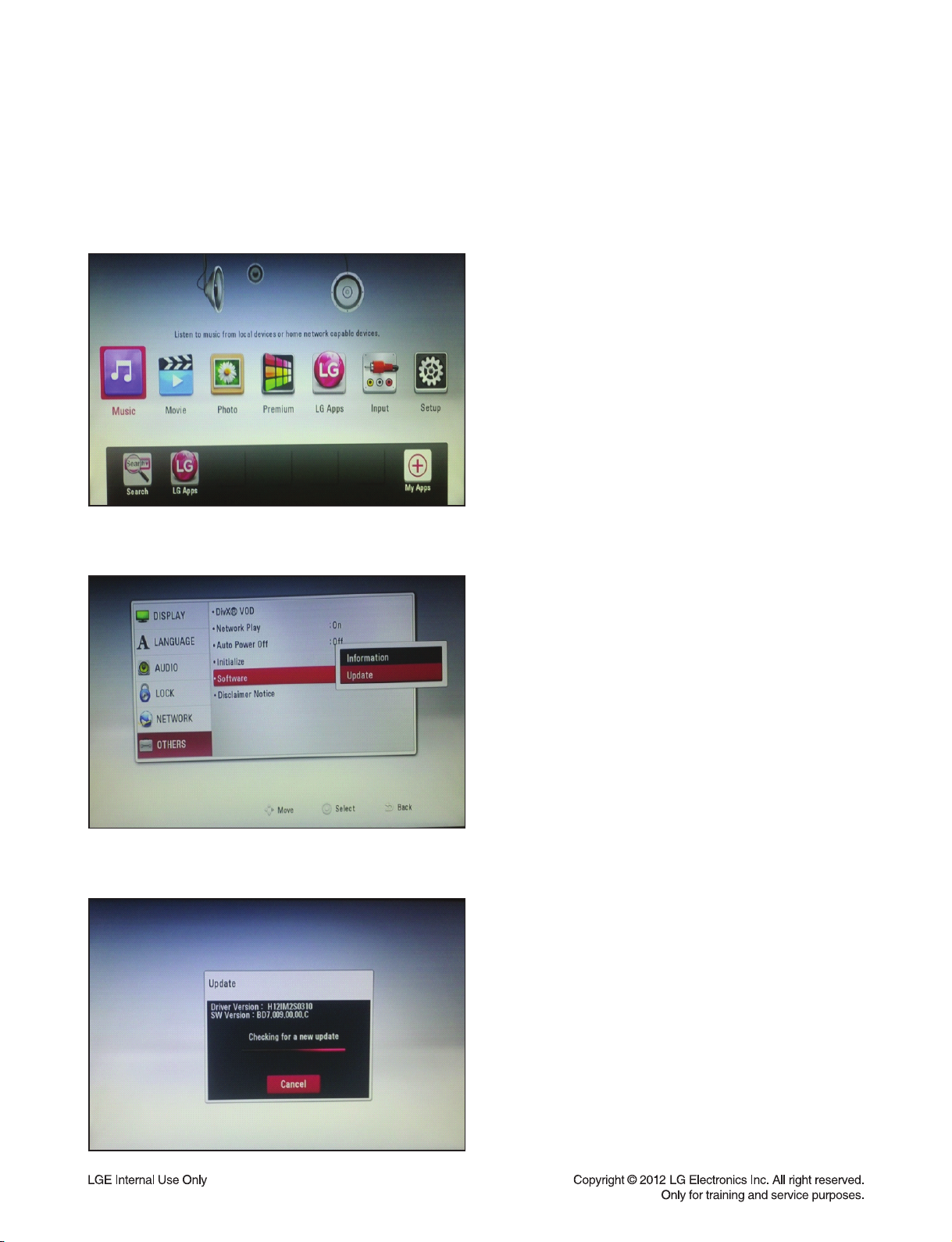
1) Press Home on the Remote Control.
2) Press or select the Setup mode.
3) Select Others --> Software Update
4) On the UPDATE window, press or ENTER to
check for the newest update.
(Checking will takes about one minute.)
Caution:
Pressing Enter while checking for the update will end
process.
1-8
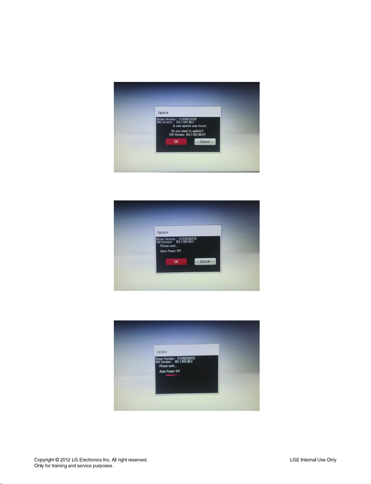
Page 10
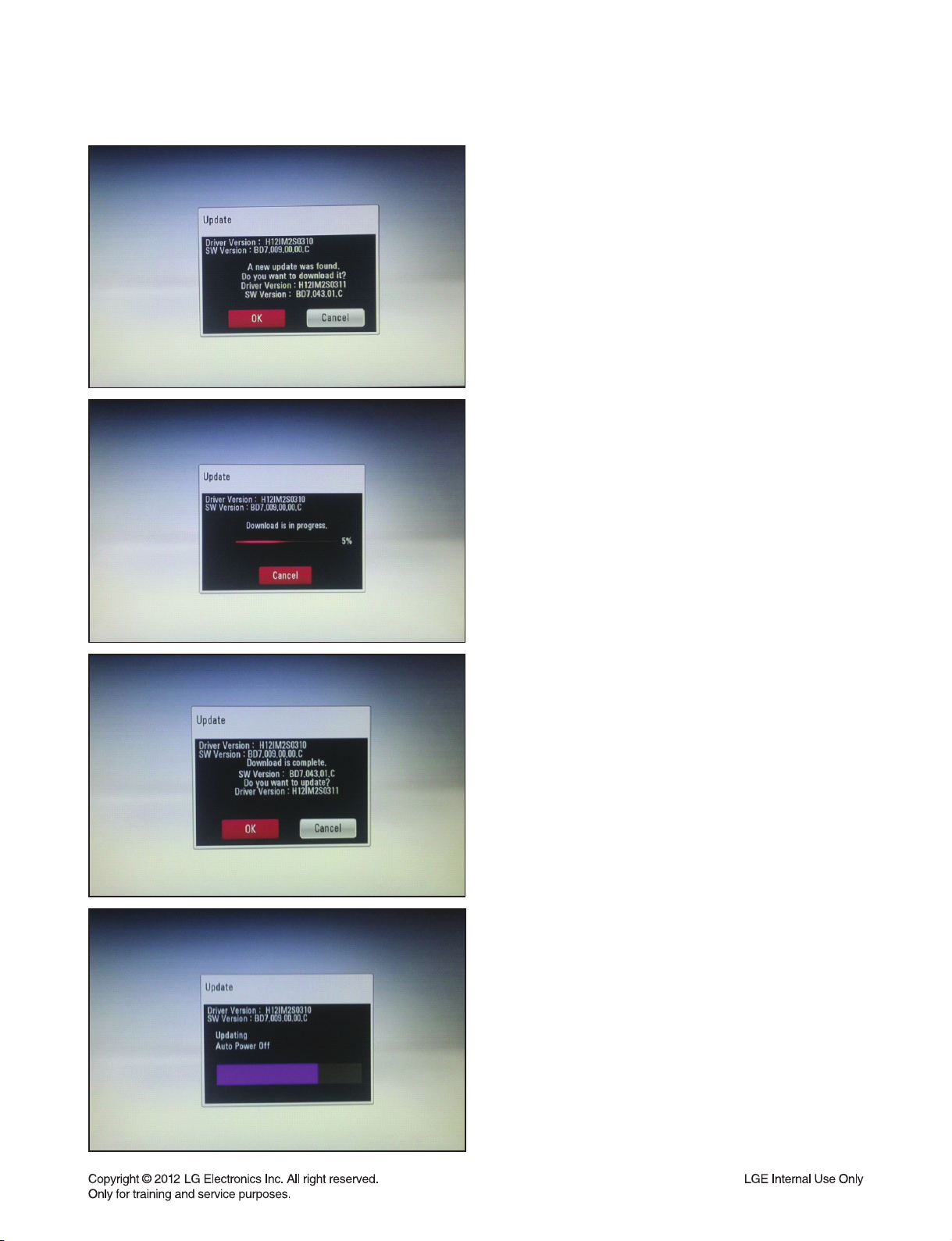
If newer version exists,
5) If newer version exists, the message
“A new update was found. Do you want to
download it?” appears.
Select OK to download the update.
(Selecting CANCEL will end the update.)
6) The player starts downloading the newest update
from the SBP server.
7) When downloading is completed, the message,
“Download is complete. Do you want to
update?” appears.
8) Select OK to start updating.
9) Update will be processed
Caution :
Do not turn off the power during fi rmware update.
10) When update is completed,
the system will turn off automatically.
1-9
Page 11

SPECIFICATIONS
• GENERAL
Power requirements Refer to main label on the rear panel.
Power consumption Refer to main label on the rear panel.
Dimensions (W x H x D) Approx. 440 X 65 X 297 mm
Net Weight (Approx.) 3.3 kg
Operating temperature 5 °C to 35 °C (41 °F to 95 °F)
Operating humidity 5 % to 90 %
• INPUTS/OUTPUTS
VIDEO OUT 1.0 V (p-p), 75 Ω, sync negative, RCA jack x 1
HDMI IN/OUT (video/audio) 19 pin (Type A, HDMI™ Connector)
ANALOG AUDIO IN 2.0 Vrms (1 kHz, 0 dB), 600 Ω, RCA jack (L, R) x 1
DIGITAL IN (OPTICAL) 3 V (p-p), Optical jack x 1
PORT. IN 0.5 Vrms (3.5 mm stereo jack)
• TUNER
FM Tuning Range 87.5 to 108.0 MHz or 87.50 to 108.00 MHz
• AMPLIFIER
Power output (4 Ω/ 3 Ω), (RMS), THD 10 %
Total 1 100 W
Front 180 W x 2
Center 180 W
Rear 180 W x 2
Sub-Woofer 200 W (Passive)
• WIRELESS RECEIVER
Power requirements Refer to main label on the wireless receiver
Power consumption Refer to main label on the wireless receiver
External dimensions (WxHxD) 60 X 220 X 175 mm
Net Weight 0.9 kg
• SYSTEM
Laser Semiconductor laser
Wavelength 405 nm / 650 nm
Signal system Standard PAL/NTSC color TV system
Frequency response 20 Hz to 18 kHz (48 kHz, 96 kHz, 192 kHz sampling)
Harmonic distortion Less than 0.05 %
Dynamic range More than 80 dB
LAN port Ethernet jack x 1, 10BASE-T / 100BASE-TX
Wireless LAN (internal antenna) Integrated IEEE 802.11n (2.4 GHz band) wireless
networking access, compatible with 802.11b/g Wi-Fi networks.
Bus Power Supply (USB) DC 5 V 2.1 A
1-10
Page 12

• SPEAKERS
Front speaker (Left/ Right)
Type 2 Way 3 speaker
Impedance Rated 4 Ω
Input Power 180 W
Max. Input power 360 W
Net Dimensions (W x H x D) 250 x 1 200 x 250 mm
Net Weight 4.1 kg
Rear speaker (Left/ Right)
Type 1 Way 1 speaker
Impedance Rated 4 Ω
Input Power 180 W
Max. Input power 360 W
Net Dimensions (W x H x D) 88 x 126 x 87 mm
Net Weight 0.6 kg
Center speaker
Type 2 Way 3 speaker
Impedance Rated 4 Ω
Input Power 180 W
Max. Input power 360 W
Net Dimensions (W x H x D) 330 x 93 x 74 mm
Net Weight 1.3 kg
Subwoofer
Type 1 Way 1 speaker
Impedance Rated 3 Ω
Input Power 200 W
Max. Input power 400 W
Net Dimensions (W x H x D) 251 x 336 x 347 mm
Net Weight 6.3 kg
• Design and specifications are subject to change without notice.
1-11
Page 13

MEMO
1-12
Page 14

SECTION 2 ELECTRICAL
CONTENTS
DIGITAL DISPLAY & MEDIA TRAINING MASTER ............................................................................................................. 2-2
1. DISTORTED PICTURE ..............................................................................................................................................2-2
2. NO PICTURE .............................................................................................................................................................2-7
3. PICTURE COLOR ....................................................................................................................................................2-12
4. NOISE/AUDIO PROBLEMS .....................................................................................................................................2-14
5. MISCELLANEOUS ................................................................................................................................................... 2-17
6. BLU-RAY PLAYER ................................................................................................................................................... 2-26
ONE POINT REPAIR GUIDE .............................................................................................................................................. 2-27
1. NO POWER PROBLEM ........................................................................................................................................... 2-27
2. NO BOOTING WHEN YOU TURN THE UNIT ON, NO MESSAGE OR “WELCOME” ON FRONT PANEL .......... 2-29
3. WIRED NETWORK CONNECTION ERROR ........................................................................................................... 2-38
4. WIRELESS NETWORK CONNECTION ERROR .................................................................................................... 2-39
5. BAD HDMI VIDEO / AUDIO OUTPUT ..................................................................................................................... 2-40
6. NO AUDIO FROM SPEAKER ..................................................................................................................................2-41
7. NO USB .................................................................................................................................................................... 2-42
ELECTRICAL TROUBLESHOOTING GUIDE ..................................................................................................................... 2-43
1. SYSTEM POWER SUPPLY ON SMPS BOARD ..................................................................................................... 2-43
2. AMP POWER SUPPLY ON SMPS BOARD ............................................................................................................ 2-46
3. POWER SUPPLY ON MAIN BOARD ...................................................................................................................... 2-47
4. SYSTEM PART ........................................................................................................................................................ 2-53
5. NO CVBS VIDEO OUTPUT ..................................................................................................................................... 2-55
6. NO HDMI OUTPUT .................................................................................................................................................. 2-56
7. NO AUDIO OUTPUT ................................................................................................................................................ 2-57
WAVEFORMS ...................................................................................................................................................................... 2-58
1. SYSTEM PART - 1 ................................................................................................................................................... 2-58
2. SYSTEM PART - 2 (SYSTEM MEMORY) ............................................................................................................... 2-59
3. VIDEO PART (100% FULL COLOR BAR) ............................................................................................................... 2-60
4. AUDIO PART - 1 (S/PDIF) ....................................................................................................................................... 2-61
5. AUDIO PART - 2 (I2S) ............................................................................................................................................. 2-62
6. HDMI PART .............................................................................................................................................................. 2-63
WIRING DIAGRAM .............................................................................................................................................................. 2-65
BLOCK DIAGRAM .............................................................................................................................................................. 2-67
CIRCUIT DIAGRAMS .......................................................................................................................................................... 2-69
1. SMPS CIRCUIT DIAGRAM ...................................................................................................................................... 2-69
2. MAIN - CPU CIRCUIT DIAGRAM ............................................................................................................................ 2-71
3. MAIN - MEMORY CIRCUIT DIAGRAM ................................................................................................................... 2-73
4. MAIN - LOADER CIRCUIT DIAGRAM ..................................................................................................................... 2-75
5. MAIN - MICOM CIRCUIT DIAGRAM ....................................................................................................................... 2-77
6. MAIN - HDMI CIRCUIT DIAGRAM .......................................................................................................................... 2-79
7. MAIN - ADC/DIR CIRCUIT DIAGRAM ..................................................................................................................... 2-81
8. MAIN - DSP CIRCUIT DIAGRAM ............................................................................................................................ 2-83
9. MAIN - POWER CIRCUIT DIAGRAM ...................................................................................................................... 2-85
10. MAIN - I/O CIRCUIT DIAGRAM ............................................................................................................................... 2-87
11. AMP - PWM CIRCUIT DIAGRAM ............................................................................................................................ 2-89
12. AMP - AMP CIRCUIT DIAGRAM ............................................................................................................................. 2-91
13. JACK CIRCUIT DIAGRAM (OPTIONAL PART) ....................................................................................................... 2-93
14. FRONT CIRCUIT DIAGRAM .................................................................................................................................... 2-97
CIRCUIT VOLTAGE CHART ............................................................................................................................................... 2-99
PRINTED CIRCUIT BOARD DIAGRAMS ......................................................................................................................... 2-101
1. SMPS P. C. BOARD ..............................................................................................................................................2-101
2. MAIN P. C. BOARD ............................................................................................................................................... 2-103
3. AMP P. C. BOARD ................................................................................................................................................. 2-107
4. JACK P. C. BOARD (OPTIONAL PART) ...............................................................................................................2-109
5. FRONT P. C. BOARD ............................................................................................................................................ 2-111
2-1
Page 15
DIGITAL DISPLAY & MEDIA TRAINING MASTER
Objective: To provide clear and concise guidelines for customer service agents to handle calls on
box goods calls.
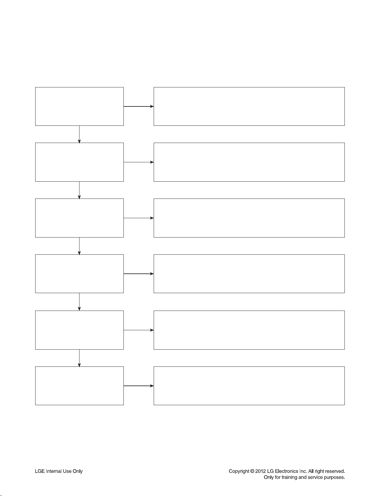
1. DISTORTED PICTURE
1-1. Lines on Picture
Distorted picture refers to the customer getting video, but there is a problem with the video.
Determine what cables the customer is using to connect
What cables is
the customer using to
connect the BD?
YES
NO
the BD to the TV and if connected properly. Refer to OM for
connections. Tighten any loose cables. Make sure the customer
is not connecting a BD to VCR or BD to DVD Recorder.
Copy protection can distort the picture on older DVD models.
Is the TV set
to the correct input?
YES
Do ghosting appear
when watching multiple discs?
YES
Do lines appear
when watching multiple discs?
YES
Does ghosting appear
when the BD is connected to
another TV?
NO
NO
NO
NO
Make sure the TV is on the correct input.
Turn TV off, then on to determine input.
Video when using composite, or component.
DVI when using DVI, and HDMI when using HDMI.
One disc displaying the issue is a problem with the disc.
Multiple discs displaying the problem could indicate the BD lens needs to
be cleaned. Recommend the customer use a lens cleaner on the BD.
A lens cleaner is available at any local electronics retailer.
One disc displaying the issue is a problem with the disc.
Multiple discs displaying the problem could indicate the BD lens needs to
be cleaned. Recommend the customer use a lens cleaner on the BD.
A lens cleaner is available at any local electronics retailer.
Connect the BD to another TV and play a disc.
No ghosting during disc play back indicates a problem with the first TV.
Please refer to the owners manual for instructions on how to connect
the BD to a TV. If the BD has a problem on the second TV,
then see service chart for service information.
YES
Has the customer tried
another set of cables?
NO
Have the customer try another set of cables. A bad cable can
also cause video problems. Test the cable with another device to
the TV to also determine if the TV is bad. If BD is problem,
please see service chart for service information.
2-2
Page 16

DIGITAL DISPLAY & MEDIA TRAINING MASTER
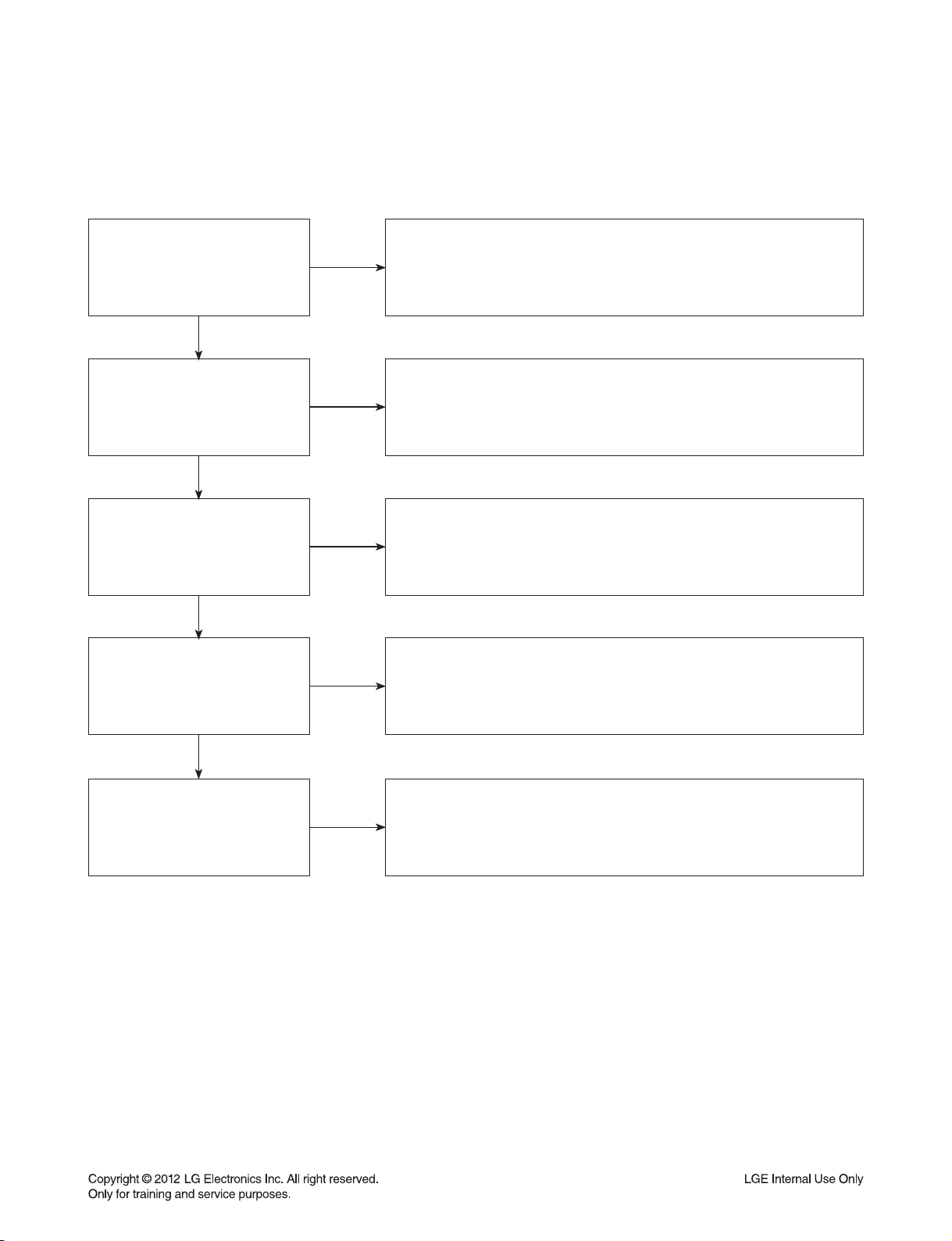
1-2. Ghost Picture
Distorted picture refers to the customer getting video, but there is a problem with the video.
Determine what cables the customer is using to connect the BD to
What cables is the customer
using to connect the BD?
YES
NO
the TV and if connected properly. Refer to OM for connections.
Tighten any loose cables. Make sure the customer is not connecting a
BD to VCR or BD to DVD Recorder. Copy protection can distort
the picture on older VCR models.
Is the TV set to
the correct input?
YES
Do ghosting appear when
watching multiple discs?
YES
Do lines appear when
watching a TV program?
YES
Does ghosting
appear when the BD is
connected to another TV?
NO
NO
NO
NO
Make sure the TV is on the correct input. Turn TV off,
then on to determine input. Video when using composite,
or component. DVI when using DVI, and HDMI when using HDMI.
One disc displaying the issue is a problem with the disc.
Multiple discs displaying the problem could indicate the BD lens
needs to be cleaned. Recommend the customer use a lens cleaner
on the BD. A lens cleaner is available at any local electronics retailer.
Ghosting appearing when watching a TV program indicates an
issue with the display. If the TV program is fine, then connect
the BD to another input on the display to determine
if the problem is following the BD.
Connect the BD to another TV and play a disc.
No ghosting during disc play back indicates a problem with the first TV.
Please refer to the owners manual for instructions on how to
connect the BD to a TV. If the BD has a problem on the second TV,
then see service chart for service information.
YES
Has the customer tried
another set of cables?
NO
Have the customer try another set of cables. A bad cable can
also cause video problems. Test the cable with another device to
the TV to also determine if the TV is bad. If BD is problem,
please see service chart for service information.
2-3
Page 17

DIGITAL DISPLAY & MEDIA TRAINING MASTER
1-3. Rolling Picture
Distorted picture refers to the customer getting video, but there is a problem with the video.
Determine what cables the customer is using to connect the BD to
What cables is the customer
using to connect the BD?
YES
NO
the TV and if connected properly. Refer to OM for connections.
Tighten any loose cables. Make sure the customer is not connecting
a BD to VCR or BD to DVD Recorder. Copy protection can distort
the picture on older VCR models.
Is the TV set to
the correct input?
YES
Does rolling appear when
watching multiple discs?
YES
Does rolling appear when
watching a TV program?
YES
Does rolling appear
when the BD is connected to
another TV?
NO
NO
NO
NO
Make sure the TV is on the correct input. Turn TV off,
then on to determine input. Video when using composite,
or component. DVI when using DVI, and HDMI when using HDMI.
One disc displaying the issue is a problem with the disc.
Multiple discs displaying the problem could indicate the BD lens
needs to be cleaned. Recommend the customer use a lens cleaner
on the BD. A lens cleaner is available at any local electronics retailer.
Rolling appearing when watching a TV program indicates
an issue with the display. If the TV program is fine, then connect
the BD to another input on the display to determine if the problem
is following the BD.
Connect the BD to another TV and play a disc. No lines during disc play
back indicates a problem with the first TV. Please refer to the owners
manual for instructions on how to connect the BD to a TV. If the BD has a
problem on the second TV, then see service chart for service information.
YES
Has the customer tried
another set of cables?
NO
Have the customer try another set of cables. A bad cable can also
cause video problems. Test the cable with another device to the TV
to also determine if the TV is bad. If BD is problem,
please see service chart for service information.
2-4
Page 18
DIGITAL DISPLAY & MEDIA TRAINING MASTER
1-4. Shaky Picture
Distorted picture refers to the customer getting video, but there is a problem with the video.
Determine what cables the customer is using to connect the BD to
What cables is the customer
using to connect the BD?
YES
NO
the TV and if connected properly. Refer to OM for connections.
Tighten any loose cables. Make sure the customer is not connecting a
BD to VCR or BD to DVD Recorder. Copy protection can distort
the picture on older VCR models.
Is the TV set to
the correct input?
YES
Does shaking appear when
watching multiple discs?
YES
Does shaking appear when
watching a TV program?
YES
Does shaking appear
when the BD is connected to
another TV?
NO
NO
NO
NO
Make sure the TV is on the correct input. Turn TV off, then on
to determine input. Video when using composite, or component.
DVI when using DVI, and HDMI when using HDMI.
One disc displaying the issue is a problem with the disc.
Multiple discs displaying the problem could indicate the BD lens
needs to be cleaned. Recommend the customer use a lens cleaner
on the BD. A lens cleaner is available at any local electronics retailer.
Shaking appearing when watching a TV program indicates
n issue with the display. If the TV program is fine, then connect
the BD to another input on the display to determine if the problem
is following the BD.
Connect the BD to another TV and play a disc. No shaking during
disc play back indicates a problem with the first TV. Please refer to
the owners manual for instructions on how to connect the BD to a TV.
If the BD has a problem on the second TV,
then see service chart for service information.
YES
Has the customer tried
another set of cables?
NO
Have the customer try another set of cables. A bad cable can
also cause video problems. Test the cable with another device to
the TV to also determine if the TV is bad. If BD is problem,
please see service chart for service information.
2-5
Page 19

DIGITAL DISPLAY & MEDIA TRAINING MASTER
1-5. Blurry Picture
Distorted picture refers to the customer getting video, but there is a problem with the video.
Determine what cables the customer is using to connect the BD to
What cables is the customer
using to connect the BD?
YES
NO
the TV and if connected properly. Refer to OM for connections.
Tighten any loose cables. Make sure the customer is not connecting
a BD to VCR or BD to DVD Recorder. Copy protection can distort
the picture on older VCR models.
Is the TV set to
the correct input?
YES
Does blurriness appear when
watching multiple discs?
YES
Does blurriness appear when
watching a TV program?
YES
Does blurriness appear
when the BD is connected to
another TV?
NO
NO
NO
NO
Make sure the TV is on the correct input. Turn TV off,
then on to determine input. Video when using composite, or component.
DVI when using DVI, and HDMI when using HDMI.
One disc displaying the issue is a problem with the disc.
Multiple discs displaying the problem could indicate the BD lens
needs to be cleaned. Recommend the customer use a lens cleaner on
the BD. A lens cleaner is available at any local electronics retailer.
Blurriness appearing when watching a TV program indicates an
issue with the display. If the TV program is fine, then connect
the BD to another input on the display to determine if the problem
is following the BD.
Connect the BD to another TV and play a disc. No blurriness
during disc play back indicates a problem with the first TV.
Please refer to the owners manual for instructions on how to connect
the BD to a TV. If the BD has a problem on the second TV,
then see service chart for service information.
YES
Has the customer tried
another set of cables?
NO
Have the customer try another set of cables.
A bad cable can also cause video problems. Test the cable with another
device to the TV to also determine if the TV is bad. If BD is problem, please
see service chart for service information.
2-6
Page 20

DIGITAL DISPLAY & MEDIA TRAINING MASTER
2. NO PICTURE
2-1. Black Screen
The entire screen is black.
Does the BD on-screen
menu appear?
YES
What cables is the customer
using to connect the BD?
YES
Is the TV set to
the correct input?
YES
Is the customer able to
watch TV programming?
NO
NO
NO
NO
In case of customer use composite cable please make sure selecting
available resolution in the menu of the BD player, composite video can just
support 480i/p. In case of composite output is black please push the stop
button at the remote controller about 5 sec for changing 480p resolution.
Determine what cables the customer is using to connect the BD to
the TV and if connected properly. Refer to OM for connections.
Tighten any loose cables. Make sure the customer is not connecting a
BD to VCR or BD to DVD Recorder. Copy protection can distort
the picture on older VCR models.
Make sure the TV is on the correct input. Turn TV off,
then on to determine input. Video when using composite, or component.
DVI when using DVI, and HDMI when using HDMI.
If the customer is not able to watch television then he may have a
problem with his television, especially if the cable signal comes
through on a different input. If the customer can not get a TV program,
then he still may have a problem with the particular input on his TV.
YES
Can the customer connect
the BD to another TV?
YES
Has the customer tried
another set of cables?
NO
NO
Have the customer connect the BD to another TV in order to
determine if the problem is the BD or the TV. Refer to the OM for
connections assistance. If the BD works on the second TV,
then the customer has a problem with his TV.
Have the customer try another set of cables. A bad cable can
also cause video problems. Test the cable with another device to the TV
to also determine if the TV is bad. If BD is problem, please see
service chart for service information.
2-7
Page 21
DIGITAL DISPLAY & MEDIA TRAINING MASTER
2-2. Blue Screen
The entire screen is a solid blue color.
Does the BD on-screen
menu appear?
YES
What cables is the customer
using to connect the BD?
YES
Is the TV set to
the correct input?
YES
Is the customer able to
watch TV programming?
NO
NO
NO
NO
In case of customer use composite cable please make sure selecting
available resolution in the menu of the BD player, composite video can just
support 480i/p. In case of composite output is black please push the stop
button at the remote controller about 5 sec for changing 480p resolution.
Determine what cables the customer is using to connect the BD
to the TV and if connected properly. Refer to OM for connections.
Tighten any loose cables. Make sure the customer is not connecting a
BD to VCR or BD to DVD Recorder. Copy protection can distort
the picture on older VCR models.
Make sure the TV is on the correct input.
Turn TV off, then on to determine input. Video when using composite,
or component. DVI when using DVI, and HDMI when using HDMI.
If the customer is not able to watch television then he may have a
problem with his television, especially if the cable signal comes
through on a different input. If the customer can not get a TV program,
then he still may have a problem with the particular input on his TV.
YES
Can the customer connect
the BD to another TV?
YES
Has the customer tried
another set of cables?
NO
NO
Have the customer connect the BD to another TV in order to
determine if the problem is the BD or the TV. Refer to the OM for
connections assistance. If the BD works on the second TV,
then the customer has a problem with his TV.
Have the customer try another set of cables. A bad cable can also
cause video problems. Test the cable with another device to
the TV to also determine if the TV is bad. If BD is problem,
please see service chart for service information.
2-8
Page 22

DIGITAL DISPLAY & MEDIA TRAINING MASTER
2-3. Snowy Screen
A snowy picture is when black and white dots are all over the screen.
Does the BD on-screen
menu appear?
YES
What cables is the customer
using to connect the BD?
YES
Is the TV set to
the correct input?
YES
Is the customer able to
watch TV programming?
NO
NO
NO
NO
In case of customer use composite cable please make sure selecting
available resolution in the menu of the BD player, composite video can just
support 480i/p. In case of composite output is black please push the stop
button at the remote controller about 5 sec for changing 480p resolution.
Determine what cables the customer is using to connect the BD
to the TV and if connected properly. Refer to OM for connections.
Tighten any loose cables. Make sure the customer is not connecting a
BD to VCR or BD to DVD Recorder. Copy protection can distort
the picture on older VCR models.
Make sure the TV is on the correct input. Turn TV off,
then on to determine input. Video when using composite, or component.
DVI when using DVI, and HDMI when using HDMI.
If the customer is not able to watch television then he may
have a problem with his television, especially if the cable signal comes
through on a different input. If the customer can not get a TV program,
then he still may have a problem with the particular input on his TV.
YES
Can the customer connect
the BD to another TV?
YES
Has the customer tried
another set of cables?
NO
NO
Have the customer connect the BD to another TV in order to
determine if the problem is the BD or the TV. Refer to the OM for
connections assistance. If the BD works on the second TV,
then the customer has a problem with his TV.
Have the customer try another set of cables. A bad cable can
also cause video problems. Test the cable with another device to
the TV to also determine if the TV is bad. If BD is problem,
please see service chart for service information.
2-9
Page 23

DIGITAL DISPLAY & MEDIA TRAINING MASTER
2-4. No Signal
A “no signal” message appears on the screen of the display.
Does the BD on-screen
menu appear?
YES
What cables is the customer
using to connect the BD?
YES
Is the TV set to the
correct input?
YES
Is the customer able to
watch TV programming?
NO
NO
NO
NO
In case of customer use composite cable please make sure selecting
available resolution in the menu of the BD player, composite video can just
support 480i/p. In case of composite output is black please push the stop
button at the remote controller about 5 sec for changing 480p resolution.
Determine what cables the customer is using to connect the BD
to the TV and if connected properly. Refer to OM for connections.
Tighten any loose cables. Make sure the customer is not connecting a
BD to VCR or BD to DVD Recorder. Copy protection can distort
the picture on older VCR models.
Make sure the TV is on the correct input. Turn TV off,
then on to determine input. Video when using composite, or component.
DVI when using DVI, and HDMI when using HDMI.
If the customer is not able to watch television then he may have a
problem with his television, especially if the cable signal comes
through on a different input. If the customer can not get a TV program,
then he still may have a problem with the particular input on his TV.
YES
Can the customer connect
the BD to another TV?
YES
Has the customer tried
another set of cables?
NO
NO
Have the customer connect the BD to another TV in order to
determine if the problem is the BD or the TV. Refer to the OM for
connections assistance. If the BD works on the second TV,
then the customer has a problem with his TV.
Have the customer try another set of cables. A bad cable
can also cause video problems. Test the cable with another device to
the TV to also determine if the TV is bad. If BD is problem,
please see service chart for service information.
2-10
Page 24
DIGITAL DISPLAY & MEDIA TRAINING MASTER
2-5. Invalid Format or Format Not Supported
Make sure the customer’s simultaneously connecting analog component
Is the customer using a
digital cable connection?
YES
Is the customer using an
analog cable connection?
YES
NO
NO
cable with HDMI cable. And then If Copy Protected Disc is playing back,
analog component output is no picture. Only when the analog output
is 480i, you can see the picture. In case of No Copy Protected Disc,
Customer’s using an DVI , or HDMI cable connection need to set
the resolution on the product. Actually our BD can support 480i~1080p
but some TVs can just support specific resolution so in order to match
resolution between TV & BD P user can choose AUTO mode
you can see the picture regardless of the resolution.
at the setup menu.
Is the display
HDCP compliant?
YES
Has the customer tried the
device on another display?
YES
Has the customer tried
another cable?
NO
NO
NO
Make sure the display is HDCP compliant when using a DVI or
HDMI connection. A lack of HDCP compliancy on the display may
cause an invalid format or format not supported message to appear.
It can also cause a copy protection OSD to appear.
Ask the customer to connect the device to another display.
If the device starts working, then the problem may be the original display.
The customer will need to troubleshoot the display. If the device
still does not work, then the problem may be the device or the cable.
Ask the customer to replace the cable between the device and display.
If the problem is corrected, then the problem was with the cable.
If the problem continues, then the device is the problem.
Set up service according to in warranty or out of warranty procedures.
2-11
Page 25

DIGITAL DISPLAY & MEDIA TRAINING MASTER
3. PICTURE COLOR
3-1. No Color
The video displays no color and only shows in black and white.
What cables is the customer
using to connect the BD?
YES
Is the TV set to the
correct input?
YES
Does color appear when
watching multiple discs?
YES
Does color appear when
watching a TV program?
NO
NO
NO
NO
Determine what cables the customer is using to connect the BD
to the TV and if connected properly. Refer to OM for connections.
Tighten any loose cables. Make sure the customer is not connecting a
BD to VCR. Copy protection can distort the picture on older VCR models.
Make sure the TV is on the correct input according to the
connections in use. Video when using composite, or component.
DVI when using DVI, and HDMI when using HDMI.
One disc displaying the issue is a problem with the disc.
Make sure the discs the customer is using are compatible with the
BD by checking “playable discs” in the owners manual.
Multiple discs displaying the problem indicates a problem
with the BD player.
If the cable or satellite programming is connected through
another input and the customer does not get color, the customer has a
problem with his television. If a TV program does have the color,
the problem may be the BD player, the cables being used,
or the TV itself.
YES
Does color appear
when the BD is
connected to another TV?
YES
Has the customer tried
another set of cables?
NO
NO
Connect the BD to another TV and play a disc. Good color during
disc play back indicates a problem with the first TV. Please refer to the
owners manual for instructions on how to connect the BD to a TV.
If the BD has a problem on the second TV, then see service chart for
service information.
Have the customer try another set of cables. A bad cable can
also cause video problems. Test the cable with another device to
the TV to also determine if the TV is bad. If the BD is the problem,
please see service chart for service information.
2-12
Page 26

DIGITAL DISPLAY & MEDIA TRAINING MASTER
3-2. Poor Color
The color is poor. Examples would be washed out colors, colors bleeding into one another, or a solid tint to
a screen.
What cables is the customer
using to connect the BD?
YES
Is the TV set to the
correct input?
YES
Is color fine
when watching multiple discs?
YES
Is color fine
when watching a TV program?
NO
NO
NO
NO
Determine what cables the customer is using to connect the BD to
the TV and if connected properly. Refer to OM for connections.
Tighten any loose cables. Make sure the customer is not connecting a
BD to VCR. Copy protection can distort the picture on older VCR models.
Make sure the TV is on the correct input according to the
connections in use. Video when using composite, or component.
DVI when using DVI, and HDMI when using HDMI.
One disc displaying the issue is a problem with the disc.
Make sure the discs the customer is using are compatible with the BD
by checking “playable discs” in the owners manual. Multiple discs
displaying the problem indicates a problem with the BD player.
If the cable or satellite programming is connected through another
input and the customer does not get color, the customer has a problem
with his television. If a TV program does have the color, the problem
may be the BD player, the cables being used, or the TV itself.
YES
Is color fine when the BD is
connected to another TV?
YES
Has the customer tried
another set of cables?
NO
NO
Connect the BD to another TV and play a disc.
Good color during disc play back indicates a problem with the first TV.
Please refer to the owners manual for instructions on how to connect
the BD to a TV. If the BD has a problem on the second TV,
then see service chart for service information.
Have the customer try another set of cables. A bad cable
can also cause video problems. Test the cable with another device to
the TV to also determine if the TV is bad. If the BD is the problem,
please see service chart for service information.
2-13
Page 27

DIGITAL DISPLAY & MEDIA TRAINING MASTER
4. NOISE/AUDIO PROBLEMS
4-1. No Audio
The customer is not able to get audio.
What cables is the customer
using to connect the BD?
YES
NO
Determine what cables the customer is using to connect the BD
to the TV and if connected properly. Refer to OM for connections.
Tighten any loose cables. Make sure the customer has audio cables
connected if using an HDMI to DVI adapter or video-only cables
(DVI, component, etc).
Is the customer
able to see video?
YES
Does issue occur on
more than one disc?
YES
Problem occur when
watching TV program?
YES
Does the problem occur
when BD is connected to
another TV?
NO
NO
NO
NO
Make sure the customer has not routed video
and audio to separate inputs.
Problem occurring on one disc indicates a problem with the disc.
Problem occurring on multiple discs could indicate a lens cleaner
is needed. The customer can purchase a lens cleaner at any
electronics retailer.
No audio from a TV program on a different channel or input means
there is a problem with the television. If a TV program does have
the audio, the problem may be the BD player, the cables being used,
or the TV itself.
Audio is fine when the BD is connected to
another TV indicates the problem is with the television.
Refer to the owners manual for assistance
with connecting BD to another TV.
YES
Has the customer tried
another set of cables?
NO
Have the customer try another set of cables. A bad cable can also
cause audio problems. Test the cable with another device to
the TV to also determine if the TV is bad. If BD is problem,
please see service chart for service information.
2-14
Page 28

DIGITAL DISPLAY & MEDIA TRAINING MASTER
4-2. Distorted Audio
The audio sounds muffled, scratchy, or the audio skips.
Determine what cables the customer is using to connect the BD
What cables is the customer
using to connect the DVD?
YES
NO
to the TV and if connected properly. Refer to OM for connections.
Tighten any loose cables. Make sure the customer has audio
cables connected if using an HDMI to DVI adapter or video-only cables
(DVI, component, etc).
Is the customer
able to see video?
YES
Does issue occur on
more than one disc?
YES
Problem occur when
watching TV program?
YES
Does the problem occur
when DVD is connected to
another TV?
NO
NO
NO
NO
Make sure the customer has not routed
video and audio to separate inputs.
Problem occurring on one disc indicates a problem with the disc.
Problem occurring on multiple discs could indicate a lens cleaner
is needed. The customer can purchase a lens cleaner at any
electronics retailer.
Distorted audio from a TV program on a different channel or
input means there is a problem with the television. If a TV program
does have the audio, the problem may be the BD player, the cables
being used, or the TV itself.
Audio is fine when the BD is connected to
another TV indicates the problem is with the television.
Refer to the owners manual for assistance
with connecting BD to another TV.
YES
Has the customer tried
another set of cables?
NO
Have the customer try another set of cables. A bad cable can
also cause audio problems. Test the cable with another device to
the TV to also determine if the TV is bad. If BD is problem,
please see service chart for service information.
2-15
Page 29
DIGITAL DISPLAY & MEDIA TRAINING MASTER
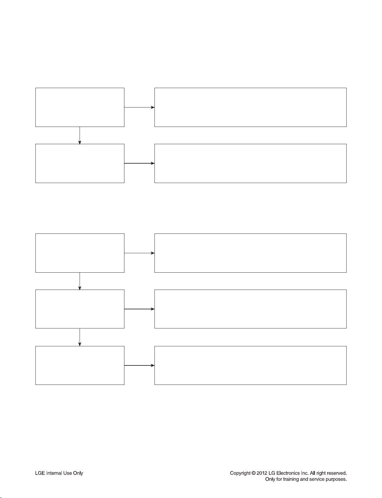
4-3. Humming/Clicking Noise
The unit is making a humming noise or a clicking noise.
Does the noise only
happen when a disc
is playing?
YES
NO
A clicking noise or a noise interfering with audio may indicate a problem.
Try multiple discs. Multiple discs with the same issue
means the BD may need service or be professionally cleaned.
BD’s make a slight hum when playing discs.
Check BD service for service instructions.
Check to see if a disc is inserted into the BD and eject the disc.
A humming or clicking noise when the disc is not inserted
may be a cooling fan. Check OM to see if cooling fan is present.
If not, unit will need service. See BD service for service instructions.
Does the noise happen
when the BD is turned on?
NO
4-4. Audio/Video Out of Synch
The audio and video do not match up. People look to be talking, but their voices are delayed by a few seconds.
If the issue only shows up on one disc, then the problem is
with that disc. Have the customer try multiple tapes or discs.
If the issue happens on multiple discs and tapes,
then ask the customer to try a lens or a head cleaner.
Make sure cables are routed properly.
Make sure audio and video cables are routed to the same source
(if possible). Routed audio and video to separate products
can cause a bit of a delay between the devices as not all devices
will process audio and video signals at the same speed.
Has the customer tried
multiple tapes and discs?
YES
How are the cables
routed?
YES
NO
NO
Has the customer
connected to another TV?
NO
Ask the customer to connect the product to another TV.
If the issue persists, try another set of cables. If the issue still persists,
then the issue is with the unit. The unit will need service.
Arrange service following proper procedure.
2-16
Page 30
DIGITAL DISPLAY & MEDIA TRAINING MASTER
5. MISCELLANEOUS
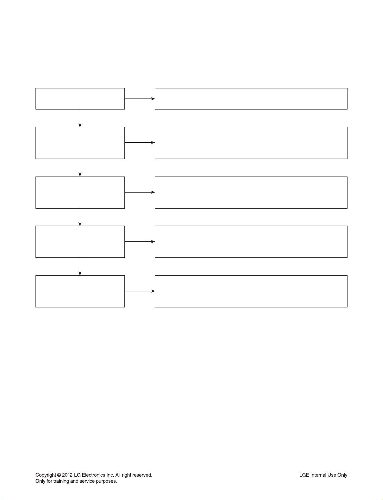
5-1. No Power
The unit will not turn on.
Is the unit plugged in?
YES
Does the unit turn on
when the power button
is pressed on the unit?
YES
Is the unit plugged into
a surge protector?
YES
Does the unit work when
plugged into another outlet?
YES
NO
NO
NO
NO
Is the unit plugged in?
See if the unit will turn on when the power button the unit is pressed.
If the unit turns on, then troubleshoot the remote control using
the Remote Control Not Working call flow.
Make sure the surge protector is plugged into a wall outlet.
Also make sure the surge protector is turned on or does not
need to be reset due to a recent surge.
Test the unit in another outlet. If the unit works,
then the problem is the outlet where the unit was connected.
If the issue is the BD, then set up service for BD according to
BD service guide.
Have there been any lightning
strikes or power outages?
NO
If BD failed due to lightning strike or a power surge,
this is not covered by warranty. Follow guidelines
for service for a BD out of warranty.
2-17
LGE Internal Use Only
Page 31

DIGITAL DISPLAY & MEDIA TRAINING MASTER
5-2. Disc Error
The unit displays “disc error” when a disc is inserted into the BD player.
Is the disc inserted into
the BD player properly?
YES
What type of disc is
the customer using?
YES
Did the customer burn
this disc in a DVD recorder?
YES
Did the customer burn
the disc in a computer?
NO
NO
NO
NO
Make sure the disc has been inserted into the BD player properly.
The player can not read a disc inserted into the unit upside down.
Determine the type of disc the customer is not able to play.
If the customer is using a store-bought movie BD,
then please skip the next three questions.
If it’s a recorded disc, move onto the next question.
Make sure the customer finalized the disc in the DVD recorder.
Make sure the type of disc the customer is using is compatible
with the BD player. If the customer initialized a DVD-RW in VR mode,
make sure the owners manual has the RW logo to show
compatibility for the VR format.
Make sure the customer burned a compatible format
(such as VCD, SVCD, or DivX). Make sure the file meets the
specifications required for the player to play the disc. Check the owners
manual for specifications. Disc may still not be compatible.
Refer customer to section of OM regarding burned discs.
YES
Has the customer tried
multiple discs?
NO
One disc with the problem is a problem with the disc.
BD players can play scratched or dirty BDs (DVDs) and not have any
issues during playback. Multiple discs with the issue can mean
the lens on the BD player needs to be cleaned. Recommend a
lens cleaner. Service BD if lens cleaner was used.
2-18
Page 32

DIGITAL DISPLAY & MEDIA TRAINING MASTER
5-3. Unit Locks Up
Unit does not respond to any commands.
Does the unit respond to
the buttons on the unit?
YES
Has the customer
reset the unit?
5-4. Disc Stuck
A BD disc is stuck in the unit.
Does the open/close button
on the unit work?
YES
NO
NO
NO
If the unit will turn on or off with the button on the unit,
troubleshoot the remote control. Please refer to
Remote Control Not Working call flow.
If the unit does no respond to any buttons,
then reset the unit by unplugging it for 15 to 30 seconds.
If the unit does not respond after the reset,
arrange for service on the BD.
Press the open/close button on the unit. If the disc ejects,
troubleshoot the remote using the Remote Control
not working call flow.
Has the customer
reset the unit?
NO
Ask the customer to reset the unit by unplugging the unit
from the electrical outlet for 15 to 30 seconds. If the disc
remains stuck in the unit after the reset, the unit will need service.
2-19
Page 33

DIGITAL DISPLAY & MEDIA TRAINING MASTER
5-5. Remote Control Not Working
Does the unit respond to
buttons on the front of the unit?
YES
Does the remote control
any component?
YES
Have the batteries
been changed?
YES
Is the remote working
at all?
NO
NO
NO
NO
If the buttons on the front of the unit do not respond,
determine if the product has locked up or if the unit will not turn on.
The problem is not the remote control. Make sure the remote control is
the remote that goes with that particular model.
Determine which product the remote is not working.
The customer may need to press the appropriate mode button
to make the remote operate another component. The remote may
even need to be programmed to the other component,
especially if the batteries were just changed.
Ask the customer to change batteries.
Make sure the batteries are new and fresh.
The batteries do not need to come from a “spare” battery drawer.
Do not mix used and new batteries.
If the remote does not work anything, then walk the customer
through a remote drain. Remove the batteries from the remote control.
Then press and hold any button down for a minute.
This will drain the power out of the remote and reset it.
Universal remotes will have to be reprogrammed.
YES
Does any remote
work the unit?
YES
Does the customer want to
program their remote?
NO
NO
If another remote works the unit, then follow
the procedure to FOC the customer a new remote.
If two remotes do not work the unit, the unit will need service.
Please refer to the OM for instructions on how to
program remote to TV. Customer wants to program a remote
other than Zenith or LG, the customer will need to contact
the manufacturer of the remote control. Codes do not work,
remote is not compatible.
2-20
Page 34

DIGITAL DISPLAY & MEDIA TRAINING MASTER
5-6. Will Not Play Disc
The unit will not play a disc when a disc is inserted into the player.
Is the disc inserted into
the BD player properly?
YES
What type of disc is
the customer using?
YES
Did the customer burn this
disc in a DVD recorder?
YES
Did the customer burn
the disc in a computer?
NO
NO
NO
NO
Make sure the disc has been inserted into the BD player properly.
The player can not read a disc inserted into the unit upside down.
Determine the type of disc the customer is not able to play.
If the customer is using a store-bought BD, then please skip the
next three questions. If it’s a recorded disc,
move onto the next question.
Make sure the customer finalized the disc in the DVD recorder.
Make sure the type of disc the customer is using is compatible
with the BD player. If the customer initialized a DVD-RW in VR mode,
make sure the owners manual has the RW logo to show
compatibility for the VR format.
Make sure the customer burned a compatible format
(such as VCD, SVCD, or DivX). Make sure the file meets the
specifications required for the player to play the disc.
Check the owners manual for specifications. Disc may still not be
compatible. Refer customer to section of OM regarding burned discs.
YES
Has the customer tried
multiple discs?
NO
One disc with the problem is a problem with the disc.
BD players can play scratched or dirty BD’s (DVD s) and not have any
issues during playback. Multiple discs with the issue can mean the lens on
the BD player needs to be cleaned. Recommend a lens cleaner.
Service BD if lens cleaner was used.
2-21
Page 35

DIGITAL DISPLAY & MEDIA TRAINING MASTER
5-7. Disc Freezes or Skips
The audio and video freeze and skip during play back of a BD or DVD disc.
Is the disc inserted into
the BD player properly?
YES
What type of disc is
the customer using?
YES
Did the customer burn this
disc in a DVD recorder?
YES
Did the customer burn
the disc in a computer?
NO
NO
NO
NO
Make sure the disc has been inserted into the BD player properly.
The player can not read a disc inserted into the unit upside down.
Determine the type of disc the customer is not able to play.
If the customer is using a store-bought BD,
then please skip the next three questions. If it’s a recorded disc,
move onto the next question.
Make sure the customer finalized the disc in the DVD recorder.
Make sure the type of disc the customer is using is compatible
with the BD player. If the customer initialized a DVD-RW in VR mode,
make sure the owners manual has the RW logo to show
compatibility for the VR format.
Make sure the customer burned a compatible format
(such as VCD, SVCD, or DivX). Make sure the file meets the
specifications required for the player to play the disc. Check the owners
manual for specifications. Disc may still not be compatible.
Refer customer to section of OM regarding burned discs.
YES
Has the customer tried
multiple discs?
NO
One disc with the problem is a problem with the disc.
BD players can play scratched or dirty BDs (DVD s) and not have any
issues during playback. Multiple discs with the issue can mean the lens on
the BD player needs to be cleaned. Recommend a lens cleaner.
Service BD if lens cleaner was used.
2-22
Page 36

DIGITAL DISPLAY & MEDIA TRAINING MASTER
5-8. Can Access Menu, but Not Play a Movie
The disc menu is displayed but the disc will not play.
Go into the system information screen of the BD player.
Check the system information
screen of the BD player.
YES
NO
To access this menu, bring up the main menu. Go to TV aspect,
highlight 16:9, press 1397139 and hit enter. If sold in the US,
this should be DVD region code 1 and BD region code A.
In case of HD-DVD, there is no region code.
What is the region code of
the BD disc?
NO
If the region code of the BD disc is not A, then the BD disc
will not play on a player sold in the US. The player can play only
BD discs labeled same as the rear of the unit.
YES
What is the region code of
the DVD disc?
NO
If the region code of the DVD disc is not 1, then the DVD disc
will not play on a player sold in the US. The player can play only
DVD discs labeled same as the rear of the unit.
YES
The disc locking up on a feature needs to be reported to Q&E.
Is the disc locking up on a
disclaimer screen when the
customer presses play?
NO
See instructions on reporting problems to Q&E. For a work
around the problem, advise the customer to access the chapter list.
Start play back from chapter 1 to start the movie and avoid any
5-9. Reporting a problem to Quality & Engineering
Reporting a problem that may require a firmware update to fix.
feature lock ups.
How do I report a problem to
Quality and Engineering?
NO
Get the micom version from the system information screen.
Get the ISBN number from the back of the BD box cover
(the number under the barcode). Get the exact problem
the customer is describing Email this information to Matt Wedgman
so the issue can be reported to the factory.
2-23
Page 37

DIGITAL DISPLAY & MEDIA TRAINING MASTER
5-10. Aspect Ratio
The customer has bars on the top and bottom of the screen, the left and right of the screen, or both.
Is the movie
wide screen or
full screen?
YES
What is the aspect
ratio of the DVD disc
being played?
YES
What is the aspect
ratio of the BD player
set at?
YES
What is the resolution
of the BD player set at?
NO
NO
NO
NO
A full screen movie played on a wide screen TV will have bars
on the left and right side of the TV. The customer needs to
make sure they choose the appropriate type of movie
they want to view.
If the aspect ratio is 1.33:1 then the movie is set up for full screen
viewing. Bars will appear on the left and right side of the screen
if the TV is wide screen. If the aspect ratio is 1.85:1 or 2.35:1,
then there will be bars on the top and bottom as that ratio is
bigger than widescreen TVs (1.78:1).
Make sure the BD player aspect ratio is set to
the appropriate setting, depending on the aspect ratio of the TV.
If the customer chose 4:3 Letterbox, then bars will appear on the top
and bottom. The customer can choose the panscan setting to
get rid of the bars.
Try changing the resolution to 480i/p. 720i/p, 1080i
and 1080p resolution require a widescreen aspect ratio
which means bars will be placed on the left and right side
for full screen movies.
YES
What is the aspect ratio of
the television set at?
NO
Make sure the aspect of the television is set appropriately.
If the aspect ratio of the television is set at 4:3 when the TV
is wide screen, then a wide screen movie will show up as
letterbox with bars on the top and bottom and bars on the sides.
2-24
Page 38

DIGITAL DISPLAY & MEDIA TRAINING MASTER
5-11. My Unit Won’t be up-converted
The customer has a problem with getting the unit to change resolutions to 480i/p, 720i/p, 1080i, or 1080p.
Is the disc
currently playing?
YES
Is the customer using
component (red, blue,
and green) cables?
YES
Is the customer using
any sort of adapter cable?
YES
Is the customer using
an HDMI or DVI cable?
NO
NO
NO
NO
Ask the customer to press stop to stop the disc from playing.
Ask the customer to press the resolution button to change the resolution.
The BD player will not change resolutions while the disc is playing.
Copy protection Discs can’t be up-converted above 480p
when using component cables. The component output does not have
HDCP (high bandwidth digital content protection) compliancy
which causes the BD player to switch from 720p or 1080i to 480p.
RGB to DVI or RGB to HDMI adapters will not up-convert
RGB outputs and inputs are not HDCP compliant. If the customer sees
an error message about HDCP, this is the issue. Copy protected discs
will not be up-converted when HDCP is not found on the input or output.
Regular discs can be converted to 1080p just through the HDMI output.
The TV must have HDCP compliancy on the HDMI input.
The display has to accept the resolution (480i/p, 720i/p, 1080i, or 1080p).
YES
Is the customer using an
HDMI to DVI cable?
YES
Has the customer tried
multiple discs?
NO
NO
Some movie companies will not allow their discs to upconvert
past 480p. If only one disc poses a problem, then the issue is the disc.
The customer will need to try multiple discs.
One disc not upconverting means the disc may not upconvert.
Some movie companies will not allow their discs to upconvert.
If multiple discs display the issue, remove the disc and change
the resolution with no disc in the unit.
If resolution will not change, the unit needs service.
2-25
Page 39

DIGITAL DISPLAY & MEDIA TRAINING MASTER
6. BLU-RAY PLAYER
6-1. Slow Loading Times for BD’s
Why does it take so long
to load my BD’s?
6-2. Booting Times
Why does it take
so long to boot my BD?
NO
NO
When a customer switches from one disc to another,
the lens have to be changed what causes the delay.
BLU-RAY require different lasers to read the discs.
The booting times for the BD is under 15 seconds.
When the set is booted,
it takes a little long time to loading the OS program.
2-26
Page 40

ONE POINT REPAIR GUIDE
1. NO POWER PROBLEM
No power problem occurs when you power on the unit.
1-1. Fuse & Bridge diode
1-1-1. Solution
Replace F901, BD901 on SMPS board.
1-1-2. How to troubleshoot (Countermeasure)
1) Look at the physical of fuse F901.
2) Check the bridge diode BD901.
No Power
BD901 is Defective
1-1-3. Service hint (Any picture / Remark)
No Power
F901 is Defective
BD901
< Fuse, F901 >
Can look at physical condition.
F901
< SMPS board top view >
2-27
Page 41

ONE POINT REPAIR GUIDE
D
V
V
No power problem occurs when you power on the unit.
1-2. VFD, 14 VA, 6 VA, 3.8 VA
1-2-1. Solution
Replace D922, D923, D924, D925, D926, D927, IC901.
1-2-2. How to troubleshoot (Countermeasure)
Case 1) FLD abnormal: Check D926, D927, ZD951, ZD952, FR952 and replace it.
Case 2) 6 VA abnormal: Check D924 and replace it.
Case 3) 14 VA abnormal: Check D925 and replace it.
Case 4) 3.8 VA abnormal: Check D922, D923 and replace it.
Case 5) All voltage abnormal: Check IC901 and replace it.
Vkk No Power
D926 is Defective
No Power
D904 is Defective
Case 5
(IC901)
1-2-3. Service hint (Any picture / Remark)
FLD No Power
D927 is Defective
Case 2
(D924)
Case 4
(D923, D922)
Case 3
(D925)
No
ZD95
Case 1
(D927, D926,
ZD951, ZD952)
6VA No Power
D924 is Defective
3.8
D923,
14
Case 2
(D924)
Case 3
(D925)
Case 4
(D923, D922)
Case 5
(IC901)
Case 1
(D927, D926, ZD951, ZD952)
< SMPS board top view > < SMPS board bottom view >
2-28
Page 42

ONE POINT REPAIR GUIDE
2. NO BOOTING WHEN YOU TURN THE UNIT ON, NO MESSAGE OR
“WELCOME” ON FRONT PANEL
When you turn on your set, it will blank / no message on front panel, and stand-by led no working.
2-1. IC101 (NO 3.8 VA & 3.3 VA)
2-1-1. Solution
Replace IC101 on MAIN board.
2-1-2. How to troubleshoot (Countermeasure)
1) Please check 3.8 VA of IC101.
2) If 3.8 VA is abnormal, please check SMPS 3.8 VA and D101 diode.
3) If 3.8 VA is OK, but 3.3 VA is abnormal, replace D101 diode.
4) If 3.8 VA, 3.3 VA is OK, check X101 crystal signal.
2-1-3. Service hint (Any picture / Remark)
X101
D101
IC101
< MAIN board top view >
< MAIN board bottom view >
2-29
Page 43

ONE POINT REPAIR GUIDE
When you turn on your set, it will blank / no message or Welcome on front panel, and it will not boot-up.
2-2. IC151 (NO 3.3 V)
2-2-1. Solution
Replace IC151 on MAIN board.
2-2-2. How to troubleshoot (Countermeasure)
1) Please check 3.8 VA of IC151 pin2 (VIN).
2) If 3.8 VA is abnormal, please check SMPS 3.8 VA.
3) If 3.8 VA is OK, but 3.3 VA is abnormal at the IC151 pin3 (VOUT), replace IC151.
2-2-3. Service hint (Any picture / Remark)
< MAIN board top view >
2-30
IC151
Page 44

ONE POINT REPAIR GUIDE
When you turn on your set, it will blank / no message or Welcome on front panel, and it will not boot-up.
2-3. IC150 (NO 1.5 V)
2-3-1. Solution
Replace IC150 on MAIN board.
2-3-2. How to troubleshoot (Countermeasure)
1) Please check 1.5 V of IC150 on MAIN board.
2) If 1.5 V voltage doesn’t come out,
- Check IC150 pin13 (VCC 14 VA).
If there is no 14 V, please check 14 VA from SMPS.
3) If VCC input IC150 there are 14 VA signal,
First of all, check the pin15 is high and if it’s high, check R1F4, R1F5, R1F9, R1G4, C1G7, L1E0
and if there’s no defective component, please replace IC150.
4) After changing it, if the set is still not booting:
- Check 1.2 V / 3.3 V is normal. (please refer to other sections of this guide)
- Check crystal X501 refer to item 2-5.
- Check NAND flash IC (IC504) refer to item 2-6.
- Check DDR IC (IC502, IC503) refer to item 2-7.
- Check MT8560 IC (IC501) refer to item 2-8.
2-3-3. Service hint (Any picture / Remark)
IC150
< MAIN board top view >
2-31
Page 45

ONE POINT REPAIR GUIDE
When you turn on your set, it will blank / no message on front panel, and it will not boot-up.
2-4. IC155 (NO 1.2 V)
2-4-1. Solution
Replace IC155 on MAIN board.
2-4-2. How to troubleshoot (Countermeasure)
1) Please check 1.2 V of IC155 on MAIN board.
2) If 1.2 V voltage doesn’t come out,
- Check IC155 pin2 (VCC 14 VA).
If there is no 14 VA, please check 14 VA from SMPS.
3) If VCC input IC155 there are 14 VA signal,
First of all, check the pin6 is high and if it’s high, check R1G7, R1G8, R1C9, L1E3, C1D2, C1B4
and if there’s no defective component please replace IC155.
4) After changing it, if the set is still not booting:
- Check 1.2 V / 3.3 V is normal. (please refer to other sections of this guide)
- Check crystal X501 refer to item 2-5.
- Check NAND flash IC (IC504) refer to item 2-6.
- Check DDR IC (IC502, IC503) refer to item 2-7.
- Check MT8560 IC (IC501) refer to item 2-8.
2-4-3. Service hint (Any picture / Remark)
< MAIN board top view >
2-32
IC155
Page 46

ONE POINT REPAIR GUIDE
When you turn on your set, it will display “WELCOME” on front panel, and it will not boot-up normally.
2-5. X501
2-5-1. Solution
Replace X501 on MAIN board.
2-5-2. How to troubleshoot (Countermeasure)
1) Please check the soldering status of 27 MHz crystal (X501).
2) Please check the frequency of 27 MHz crystal (X501).
3) If the crystal doesn’t oscillate, replace X501.
4) After changing it, if the set is still not booting:
- Check NAND flash IC (IC504) refer to item 2-6.
- Check DDR IC (IC502, IC503) refer to item 2-7.
- Check MT8560 IC (IC501) refer to item 2-8.
2-5-3. Service hint (Any picture / Remark)
X501
< MAIN board top view >
2-33
Page 47

ONE POINT REPAIR GUIDE
When you turn on your set, it will display “WELCOME” on front panel, and it will not boot-up normally.
2-6. IC504 (NAND FLASH MEMORY)
2-6-1. Solution
Replace IC504 on MAIN board.
2-6-2. How to troubleshoot (Countermeasure)
1) Please check physical status of IC504 on your eyes.
2) Check the VCC (3.3 V) of IC504 and if it’s normal please replace IC504.
(Please make sure IC504 has proper program.)
3) After changing it, if the set is still not booting:
- Check DDR IC (IC502, IC503) refer to item 2-7.
- Check MT8560 IC (IC501) refer to item 2-8.
2-6-3. Service hint (Any picture / Remark)
IC504
< MAIN board bottom view >
2-34
Page 48

ONE POINT REPAIR GUIDE
When you turn on your set, it will display “WELCOME” on front panel, and it will not boot-up normally.
2-7. IC502, IC503 (DDR3 MEMORY)
2-7-1. Solution
Replace IC502, IC503 on MAIN board.
2-7-2. How to troubleshoot (Countermeasure)
1) Please check 0.75 V of DDR3_VREF. (between C545 and C546).
Please check 0.75 V of DDR3_VREF. (between C547 and C548).
Please check 1.5 V of IC502, IC503.
2) If it doesn’t work even though IC150, IC151, IC155 are no problem,
IC502, IC503 (DDR memory) could have problem.
3) After changing it, if the set is still not booting:
- Check MT8560 IC (IC501) refer to item 2-8.
- Check MAIN board refer to item 2-9.
2-7-3. Service hint (Any picture / Remark)
C546
C545
C548
C547
< MAIN board bottom view >
IC501
IC503
IC502
< MAIN board top view >
2-35
Page 49

ONE POINT REPAIR GUIDE
When you turn on your set, it will display “WELCOME” on front panel, and it will not boot-up normally.
2-8. IC501 (MPEG IC)
2-8-1. Solution
Replace IC501 on MAIN board.
2-8-2. How to troubleshoot (Countermeasure)
1) Please check 1.2 V of C595 on MAIN board.
Please check 3.3 V of C580 on MAIN board.
Please check 1.5 V of C525 on MAIN board.
2) If it doesn’t work even though IC150, IC151, IC155 are no problem,
IC501 MT8560 could have problem.
3) After changing it, if the set is still no booting, check MAIN board refer to item 2-9.
2-8-3. Service hint (Any picture / Remark)
C595 (1.2 V)
C525 (1.5 V) C580 (3.3 V)
< MAIN board top view >
IC501
< MAIN board bottom view >
2-36
Page 50

ONE POINT REPAIR GUIDE
When you turn on your set, it will display “WELCOME” on front panel, and it will not boot-up normally.
2-9. MAIN BOARD
2-9-1. Solution
Replace MAIN board.
2-9-2. How to troubleshoot (Countermeasure)
1) Please remove IC501 and IC502, IC503, IC504 and then check the Impedance between each signal
(DATA, ADDRESS, and so on).
2) If there is some Impedance (a few Ω or infinite Ω) especially power source trace,
PCB via might be broken. You’d better replace MAIN board.
2-9-3. Service hint (Any picture / Remark)
IC504
< MAIN board bottom view >
2-37
IC501
IC503
IC502
Page 51

ONE POINT REPAIR GUIDE
3. WIRED NETWORK CONNECTION ERROR
When you connect online service (like You-tube or Netflix2.1) through the wired LAN,
the “no connection“ message appears.
3-1. JK250 (ETHERNET JACK)
3-1-1. Solution
Replace JK250 on MAIN board.
3-1-2. How to troubleshoot (Countermeasure)
1) Check you internet connection. Make sure it connect properly to modem or router.
2) If internet connection OK, please check the Ethernet jack (JK250).
3) If there is soldering problem, please re-soldering pin JK250.
4) If after re-soldering problem still occurs, replace JK250.
5) If problem still occurs after replace JK250. Check MT8560 IC (IC501). Refer to item 2-8.
3-1-3. Service hint (Any picture / Remark)
JK250
< MAIN board top view >
2-38
Page 52

ONE POINT REPAIR GUIDE
4. WIRELESS NETWORK CONNECTION ERROR
When you connect online service (like You-tube or Netflix2.1) through the Wi-Fi,
the “no connection“ message appears.
4-1. Wi-Fi MODULE
4-1-1. Solution
Replace Wi-Fi module on FRONT panel.
4-1-2. How to troubleshoot (Countermeasure)
1) Check you internet connection. Make sure it connect properly to modem or router.
2) If internet connection OK, please check the CN252.
3) If there is soldering problem, please re-soldering pin CN252.
4) If after re-soldering problem still occurs, replace Wi-Fi module.
5) If problem still occurs after replace Wi-Fi module. Check MT8560 IC (IC501). Refer to item 2-8.
4-1-3. Service hint (Any picture / Remark)
< MAIN board top view >
< Wi-Fi module >
2-39
CN252
Page 53

ONE POINT REPAIR GUIDE
5. BAD HDMI VIDEO / AUDIO OUTPUT
When unit is connected to HDMI TV using HDMI cable, picture shows bad color, no output or mixed
color on the screen. But component output is OK.
5-1. JK803 (HDMI JACK)
5-1-1. Solution
Replace JK803 (HDMI Jack).
5-1-2. How to troubleshoot (Countermeasure)
1) Check JK803 pin soldering.
2) If there is short soldering on pin JK803, re-soldering pin JK803.
3) If problem still occurs, check HDMI data.
- If all data OK, replace JK803.
- If data NG, check set on BD mode:
Replace IC501.
5-1-3. Service hint (Any picture / Remark)
HDMI OUT
JK803
HDMI IN
< MAIN board top view >
2-40
Page 54

ONE POINT REPAIR GUIDE
6. NO AUDIO FROM SPEAKER
When unit is connected to speaker, no audio from speaker.
6-1. IC602 (PWM IC)
6-1-1. Solution
Replace IC602 (PWM IC).
6-1-2. How to troubleshoot (Countermeasure)
1) Check IC602 pin soldering.
2) If there is short soldering on pin IC602, re-soldering pin IC602.
3) If problem still occurs, check AMP IC (IC700, IC701, IC702).
- Check IC700, IC701, IC702 pin soldering.
- If soldering ok, check the AMP heat sink:
Replace IC700, IC701, IC702.
6-1-3. Service hint (Any picture / Remark)
AMP IC (IC700, IC701, IC702)
IC602 (PWM IC)
< AMP board top view >
< AMP heat sink view >
2-41
Page 55

ONE POINT REPAIR GUIDE
7. NO USB
When unit is connected to USB, no audio and video from SET.
7-1. IC501 (MT8560)
7-1-1. Solution
Replace IC501 (MT8560).
7-1-2. How to troubleshoot (Countermeasure)
1) Check CN202 connector and FFC cable.
2) If there is short soldering on CN202, re-soldering CN202.
3) If problem still occurs, check 5 V (CN202 pin4 ~ pin8).
- If no output, check IC150 on MAIN board.
- If OK, check USB1+, USB1- signal.
- If there is no signal, replace IC501.
7-1-3. Service hint (Any picture / Remark)
CN202
pin4 ~ pin8 : 5 V
pin10 : USB1+
pin11 : USB1-
< JACK board top view >
CN202
pin4 ~ pin8 : 5 V
pin10 : USB1+
pin11 : USB1-
< JACK (W/O MIC) board bottom view >
2-42
Page 56

ELECTRICAL TROUBLESHOOTING GUIDE
1. SYSTEM POWER SUPPLY ON SMPS BOARD
No 3.8 VA
YES
Is F901 normal?
YES
Is TH901 normal ?
YES
Is BD901 normal?
YES
Is the VCC
(11 V ~ 25 V) supplied to IC901
pin4?
YES
NO
NO
NO
NO
Replace F901 (same fuse).
Replace TH901.
Replace BD901.
Is D922 / D923 normal?
Check or replace D922 / D923.
Power line of MAIN PCB is short.
2-43
Page 57

ELECTRICAL TROUBLESHOOTING GUIDE
No 6 VA
YES
Is F901 normal?
YES
Is TH901 normal ?
YES
Is BD901 normal?
YES
Is the VCC
(11 V ~ 25 V) supplied to IC901
pin4?
YES
NO
NO
NO
NO
Replace F901 (same fuse).
Replace TH901.
Replace BD901.
Is D924 normal?
Check or replace D924.
Power line of MAIN PCB is short.
2-44
Page 58

ELECTRICAL TROUBLESHOOTING GUIDE
No 14 VA
YES
Is F901 normal?
YES
Is TH901 normal ?
YES
Is BD901 normal?
YES
Is the VCC
(11 V ~ 25 V) supplied to IC901
pin4?
YES
NO
NO
NO
NO
Replace F901 (same fuse).
Replace TH901.
Replace BD901.
Is D925 normal?
Check or replace D925.
Power line of MAIN PCB is short.
2-45
Page 59

ELECTRICAL TROUBLESHOOTING GUIDE
2. AMP POWER SUPPLY ON SMPS BOARD
No 36 VA / 26 VA
YES
Is the P-CTL normal?
YES
Is the VCC
(11 V ~ 25 V) supplied to IC902
pin7?
YES
Is IC902 normal?
YES
Is Q901 normal?
YES
NO
NO
NO
NO
Check MICOM IC.
Is Q910 normal?
Check or replace Q910.
Replace IC902.
Replace Q901.
Is D928 normal?
YES
Power line of MAIN or AMP PCB is short.
NO
2-46
Replace D928.
Page 60

ELECTRICAL TROUBLESHOOTING GUIDE
3. POWER SUPPLY ON MAIN BOARD
No 3.3 V
YES
Is the
VCC supplied to IC151
pin2?
YES
Is there
signal at IC151
pin1?
YES
Check IC151 and replace.
No 3.3 VA (3.3VA_MICOM)
NO
NO
Check 3.8 VA on SMPS board.
Check IC101 pin58 (DCDC33_CTRL).
YES
Is D101 diode input
supply 3.8 VA?
YES
Check D101 and replace.
NO
2-47
Check 3.8 VA on MAIN board.
Page 61

ELECTRICAL TROUBLESHOOTING GUIDE
No 12 V (12V_LOADER)
YES
Is the
VCC supplied to IC156
pin2?
YES
Is there
signal at IC156
pin1?
YES
Check IC156 and replace.
No 9.5 V (A9P5V)
NO
NO
Check 14 VA on SMPS board.
Check IC101 pin68 (LDO_CTRL).
YES
Is the
VCC supplied to IC702
pin2?
YES
Is there
signal at IC702
pin1?
YES
Check IC702 and replace.
NO
NO
2-48
Check 14 VA on SMPS board.
Check IC101 pin61 (PWR_CTRL).
Page 62

ELECTRICAL TROUBLESHOOTING GUIDE
No 5 V (5V_LOADER)
YES
Is the
VCC supplied to IC703
pin2?
YES
Is there
signal at IC703
pin1?
YES
Check IC703 and replace.
No 1.8 V (DVDD18 / PLLVDD18) IC801 HDMI
NO
NO
Check 6 VA on SMPS board.
Check IC101 pin61 (PWR_CTRL).
YES
Is the
VCC supplied to IC803, IC810
pin3?
YES
Check IC803, IC810 and replace.
NO
2-49
Check IC151 pin3 (VCC_3V3).
Page 63

ELECTRICAL TROUBLESHOOTING GUIDE
No 1.8 V (DSP VDD18) IC401 DSP
YES
Is the
VCC supplied to IC405
pin3?
YES
Check IC405 and replace.
No 5 V (SYSTEM VCC_5V)
NO
Check IC151 pin3 (VCC_3V3).
YES
Is the
VCC supplied to IC153
pin2?
YES
Is there
signal at IC153
pin1?
YES
Check IC153 and replace.
NO
NO
2-50
Check 6 VA on SMPS board.
Check IC101 pin68 (LDO_CTRL).
Page 64

ELECTRICAL TROUBLESHOOTING GUIDE
No 5 V (MIC AVCC_5V)
YES
Is the
VCC supplied to IC154
pin2?
YES
Is there
signal at IC154
pin1?
YES
Check IC154 and replace.
No 5 V (5V_IPOD / USB_5V)
NO
NO
Check 6 VA on SMPS board.
Check IC101 pin68 (LDO_CTRL).
YES
Is the
VCC supplied to IC150
pin8?
YES
Is there
signal at IC150
pin6?
YES
Check IC150 and replace.
NO
NO
2-51
Check 14 VA on SMPS board.
Check IC101 pin68 (LDO_CTRL).
Page 65

ELECTRICAL TROUBLESHOOTING GUIDE
No 1.5 V
YES
Is the
VCC supplied to IC150
pin13?
YES
Is there
signal at IC150
pin15?
YES
Check IC150 and replace.
No 1.2 V
NO
NO
Check 14 VA on SMPS board.
Check IC101 pin59 (DCDC15_CTRL).
YES
Is the
VCC supplied to IC155
pin2?
YES
Is there
signal at IC155
pin6?
YES
Check IC155 and replace.
NO
NO
2-52
Check 14 VA on SMPS board.
Check IC101 pin60 (DCDC12_CTRL).
Page 66

ELECTRICAL TROUBLESHOOTING GUIDE
4. SYSTEM PART
Power on
YES
4B
Stand-by LED
OK?
YES
NO
3.3 VA, 3.8 VA
OK?
YES
IC101: 3.3 VA /
IC150 : 1.5 V / IC151 : 3.3 V /
IC155 : 1.2 V OK?
YES
X501
27.000 MHz
OK?
YES
Replace IC501 MT8560.
NO
NO
NO
Check D101
and 3.8 VA on SMPS board.
Check IC101 / IC150 / IC151 /
IC155 and SMPS board.
Replace X501.
Main Board
4A
3.8 VA, 3.3 VA
OK?
YES
2-53
NO
NO
Check D301
and CN305 pin11.
Check IC3T1.IC3T1 3.3 VA OK?
Front Board
Page 67

ELECTRICAL TROUBLESHOOTING GUIDE
4A
“LG Logo”
display on monitor
OK?
YES
NO
IC101: 3.3 VA /
IC150 : 1.5 V / IC151 : 3.3 V /
IC155 : 1.2 V OK?
YES
X501
27.000 MHz
OK?
YES
Signal
NF_ALE, NF_CLE
OK?
YES
Replace IC501 MT8560
or IC502, IC503.
NO
NO
NO
Check IC101 / IC150 / IC151 /
IC155 and SMPS board.
Replace X501.
Replace IC504
(NAND Flash).
“LG Logo”
display on monitor
OK?
YES
System part OK.
NO
4B
YES
Display
cable connection
OK ?
2-54
NO
Proper display
cable connect.
Page 68

ELECTRICAL TROUBLESHOOTING GUIDE
5. NO CVBS VIDEO OUTPUT
No CVBS / COMPOSITE
video on display
YES
Is there
CVBS signal
on L2V1?
YES
Is there
CVBS signal out
of L2V1?
YES
Is there
signal on D201?
YES
Check JK251
and RCA cable connection.
NO
NO
NO
Check IC501’s VCC
or replace IC501.
Replace L2V1.
D201
5 V OK?
YES
Replace D201.
NO
Check IC153.
2-55
Page 69

ELECTRICAL TROUBLESHOOTING GUIDE
6. NO HDMI OUTPUT
No HDMI audio / video output
YES
IC801
VCC 3V3 & 1.8 V
OK?
YES
IC101
HDMI_SDA, SCL, HDMI_RST
CEC_RX&TX, HDMI_RX_INT
OK?
YES
JK803 pin18
VCC 5 V OK?
YES
JK803 pin19 HPD
about 3.3 V OK?
YES
Is there signal on
pin1, 3, 4, 6, 7, 9, 10, 12?
YES
NO
NO
NO
NO
NO
Check VCC 3V3 & 1.8 V
IC803, IC810, IC151.
Check IC101.
Check VCC 5 V from IC153.
Check hot plug detect signal from TV.
Check IC501 MT8560 VCC
or replace IC501 MT8560, IC801 HDMI IC.
HDMI output OK.
2-56
Page 70

ELECTRICAL TROUBLESHOOTING GUIDE
7. NO AUDIO OUTPUT
No AUDIO output
YES
IC602
3.3 V OK?
YES
X600
19.2 MHz OK?
YES
IC602 pin4, 5, 6, 7, 8
I2C data OK?
YES
IC700, IC701, IC702
36 V, 12 V OK?
YES
CN600
pin11, 20, 21, 22, 24
OK?
YES
NO
NO
NO
NO
NO
Check IC601 pin2 supply 3.8 VA and pin1.
Replace X600.
Check IC101
and IC401 pin47, 48, 49, 51, 52, 54.
Check SMPS 36 V and IC600 12 V.
Check IC101.
Replace IC700, IC701, IC702.
2-57
Page 71

1. SYSTEM PART - 1
WAVEFORMS
1
1
IC501 MT8560 X-TAL 27 MHz
2-58
Page 72

2. SYSTEM PART - 2 (SYSTEM MEMORY)
2
IC501 MT8560 BA0
4
3
2
5
3
IC501 MT8560 WE#
4
5
IC501 MT8560 CAS#
IC501 MT8560 CK
2-59
Page 73

3. VIDEO PART (100% FULL COLOR BAR)
6
6
CVBS
2-60
Page 74

4. AUDIO PART - 1 (S/PDIF)
7
7
CS8422_AUDIO_SPDIF IN
2-61
Page 75

5. AUDIO PART - 2 (I2S)
tjsr
8
9
8
10
11
9
10
11
ijr
syjr
kh{hW
2-62
Page 76

6. HDMI PART
12
13
12
13
H_SDA
14
14
15
H_SCL
15
HDMI_CLK_N
HDMI_0_N
2-63
Page 77

MEMO
2-64
Page 78

WIRING DIAGRAM
CN254
24P FFC
CN401
CABLE
(MAIN – AMP)
CN600
CN251
18PIN FFC
(MAIN – JACK)
MAIN
CABLE
8PIN FFC
CABLE
(MAIN – BT)
CN252
5PIN HARNESS
CABLE
(MAIN - Wi-Fi)
AMP
CN150
14PIN HARNESS
CABLE
(MAIN – SMPS)
CN250
8PIN B'd to B'd
CN901
SMPS
: HARNESS
: FFC
CN202
JACK
18PIN FFC
CABLE
(MAIN – FRONT)
CN305
OPTIONAL PART
Bluetooth
2-662-65
Wi-Fi
TOUCH
FRONT
PWR
Page 79

BLOCK DIAGRAM
6ch Stereo ADC
(CS5346)
SLAVE
Aux
Tuner
Optical
ARC
MIC
HDMI
SPDIF
SPDIF(HDMI IN)
SPDIF
ADC
AK5358
DIR_MCLK
DATA0
#2 ,RX1
MIC_DATA
LRCK
BCK
24.576 MHz
DIR
CS8422
DIR_CLKIN
SLAVE
DSPI_LRCK
DSPI_BCK
DSPI_DATA0 ,1, 2
24.576 MHz
Audio DSP
CS495314
•Sound Effect
•Bass
Management
•ChDelay
•AV sync
•Downmix
McASP0 Rx
DSPI_MCLK
DSPO_LRCK
DSPO_BCK
DSPO_D ATA0,1, 2
19.2 MHz
PS9845
SLAVE
VOUTD15
#E23
MASTER
#C24
VOUTD11
MT8560
INT
SDA
SCLK
RESET
1.2/1.5/3.3V
M_MCLK
M_LRCK
M_BCK
M_DATA0,1,2
#88 ,AP1_OUT
TMDS
No HDM I In Opt ion
TMDS
DSPI_MCLK
RX TX
ADV7622
TMDS
HDMI
W_BCK
W_LRCK
W_DATA0,1, 2
Wireless
2ch TX Module
Wireless Option
OUT
2-682-67
Page 80

CIRCUIT DIAGRAMS
1. SMPS CIRCUIT DIAGRAM
No Power
12
11
10
BD901 is Defective
Vkk No Power
D926 is Defective
No Power
D904 is Defective
IMPORTANT SAFETY NOTICE
WHEN SERVICING THIS CHASSIS, UNDER NO
CIRCUMSTANCES SHOULD THE ORIGINAL DESIGN
BE MODIFIED OR ALTERED WITH OUT PERMISSION
FROM THE LG CORPORATION. ALL COMPONENTS
SHOULD BE REPLACED ONLY WITH TYPES
IDENTICAL TO THOSE IN THE ORIGINAL CIRCUIT.
FLD No Power
D927 is Defective
No Digitron Displayed
6VA No Power
D924 is Defective
SPECIAL COMPONENTS ARE SHADED ON THE
SCHEMATIC FOR EASY IDENTIFICATION.
THIS CIRCUIT DIAGRAM MAY OCCASIONALLY
DIFFER FROM THE ACTUAL CIRCUIT USED. THIS
WAY, IMPLEMENTATION OF THE LATEST SAFETY
AND PERFORMANCE IMPROVEMENT CHANGES
INTO THE SET IS NOT DELAYED UNTIL THE NEW
SERVICE LITERATURE IS PRINTED.
ZD951, ZD952 are Defective
NOTE :
1. Shaded( ) parts are critical for safety. Replace only
with specified part number.
2. Voltages are DC-measured with a digital voltmeter
during Play mode.
9
8
7
6
5
4
No Power
F901 is Defective
No AMP Power
Q910, Q901 are Defective
S/W Error
IC901, IC902 are Defective
3.8 VA No Power
D923, D922 are Defective
14 VA No Power
D921, D925 are Defective
Switching Error
PC901~PC903 are Defective
Switching Error
IC903, IC904 are Defective
3
PVDD No Power
D928 is Defective
2
1
Warning
Parts that are shaded are critical with
respect to risk of fire or electrical shock.
EAX63689121, Rev1.5(7)
SMPS
2012. 01. 04
A
B C D E F G H I J K L M N O P Q R ST
2-702-69
Page 81

2. MAIN - CPU CIRCUIT DIAGRAM
12
11
8
10
10
9
1
9
11
4
3
8
2
5
7
6
5
4
3
2
1
: WAVEFORM NUMBER
EAX64508323(#2), Rev1.0(0)
CPU
2012. 03. 13
A
BCDEFGH I J KLMNOPQRST
2-722-71
Page 82

3. MAIN - MEMORY CIRCUIT DIAGRAM
12
11
10
9
8
7
6
5
4
3
2
1
MEMORY
EAX64508323(#3), Rev1.0(0)
2012. 03. 13
A
BCDEFGH I J KLMNOPQRST
2-742-73
Page 83

4. MAIN - LOADER CIRCUIT DIAGRAM
12
11
10
9
8
7
6
5
4
3
2
1
EAX64508323(#4), Rev1.0(0)
A
BCDEFGH I J KLMNOPQRST
LOADER
2012. 03. 13
2-762-75
Page 84

5. MAIN - MICOM CIRCUIT DIAGRAM
12
11
10
9
8
7
6
5
4
3
2
1
MICOM
EAX64508323(#5), Rev1.0(0)
2012. 03. 13
A
BCDEFGH I J KLMNOPQRST
2-782-77
Page 85

6. MAIN - HDMI CIRCUIT DIAGRAM
12
11
10
9
8
12
13
7
6
5
4
3
2
15
14
1
: WAVEFORM NUMBER
EAX64508323(#6), Rev1.0(0)
HDMI
2012. 03. 14
A
BCDEFGH I J KLMNOPQRST
2-802-79
Page 86

7. MAIN - ADC/DIR CIRCUIT DIAGRAM
12
11
10
9
8
7
7
6
5
4
3
2
1
: WAVEFORM NUMBER
EAX64508323(#7), Rev1.0(0)
ADC/DIR
2012. 03. 13
A
BCDEFGH I J KLMNOPQRST
2-822-81
Page 87

8. MAIN - DSP CIRCUIT DIAGRAM
12
11
10
9
8
7
6
5
4
3
2
1
EAX64508323(#8), Rev1.0(0)
A
BCDEFGH I J KLMNOPQRST
DSP
2012. 03. 13
2-842-83
Page 88

9. MAIN - POWER CIRCUIT DIAGRAM
12
11
10
9
8
7
6
5
4
3
2
1
POWER
EAX64508323(#9), Rev1.0(0)
2012. 03. 13
A
BCDEFGH I J KLMNOPQRST
2-862-85
Page 89

10. MAIN - I/O CIRCUIT DIAGRAM
12
11
10
9
8
6
7
6
5
4
3
2
1
: WAVEFORM NUMBER
EAX64508323(#10), Rev1.0(0)
I/O
2012. 03. 13
A
BCDEFGH I J KLMNOPQRST
2-882-87
Page 90

11. AMP - PWM CIRCUIT DIAGRAM
12
11
10
9
8
7
6
5
4
3
2
1
PWM
EAX64464003(#1), Rev1.0 (0)
2011. 12. 27
A
B C D E F G H I J K L M N O P Q R ST
2-902-89
Page 91

12. AMP - AMP CIRCUIT DIAGRAM
12
11
10
9
8
7
6
5
4
3
2
1
AMP
EAX64464003(#2), Rev1.0 (0)
2011. 12. 27
A
B C D E F G H I J K L M N O P Q R ST
2-922-91
Page 92

13. JACK CIRCUIT DIAGRAM (OPTIONAL PART)
13-1. USB & PTB & MIC CIRCUIT DIAGRAM
12
11
10
9
8
7
6
5
4
3
2
1
JACK - USB & PTB & MIC
EAX64545101(#1), Rev1.2 (3)
2011. 12. 27
A
B C D E F G H I J K L M N O P Q R ST
2-942-93
Page 93

JACK CIRCUIT DIAGRAM (OPTIONAL PART)
13-2. USB & PTB CIRCUIT DIAGRAM
12
11
10
9
8
7
6
5
4
3
2
1
JACK - USB & PTB
EAX64562101(#1), Rev1.1 (1)
2011. 12. 27
A
B C D E F G H I J K L M N O P Q R ST
2-962-95
Page 94

14. FRONT CIRCUIT DIAGRAM
12
11
10
9
8
7
6
5
4
3
2
1
FRONT
EAX64645502, Rev1.1(1)
2011. 12. 27
A
B C D E F G H I J K L M N O P Q R ST
2-982-97
Page 95

CIRCUIT VOLTAGE CHART
Pin No. Vin1 VCC
IC150 TPS65252
8 Vin1 14.1
9 LX1 5.16
12 LX2 1.52
13 Vin2 14.1
27 USB_VIN 0
28 USB_VO 0
IC151 TJ3966
2 Vin 3.82
3 Vout 3.31
IC153 LM27152
2 Vin 6.12
4 Vout 5.05
IC154 LM37102
2 Vin 6.12
3 Vout 5.09
IC155 AOZ1051
2 Vin 14.15
9 Vout 1.23
IC702 LM37102
2 Vin 14.1
3 Vout 9.51
IC703 LM37102
2 Vin 14.1
3 Vout 5.12
IC803 AZ1117
3 Vin 3.32
2 Vout 1.81
IC810 AZ1117
3 Vin 3.32
2 Vout 1.81
IC701 TPIC2050
3 P12V_3 12.2
24 A9P5V 9.51
42 P12V_1 12.2
46 P12V_2 12.2
56 P5V_2 5.104
MEMO
2-1002-99
Page 96

PRINTED CIRCUIT BOARD DIAGRAMS
1. SMPS P. C. BOARD
(TOP VIEW) (BOTTOM VIEW)
NOTE) Warning
Parts that are critical with respect to risk
of fire or electrical shock.
2-1022-101
Page 97

2. MAIN P. C. BOARD
(TOP VIEW)
2-1042-103
Page 98

MAIN P. C. BOARD
(BOTTOM VIEW)
2-1062-105
Page 99

3. AMP P. C. BOARD
(TOP VIEW) (BOTTOM VIEW)
2-1082-107
Page 100

4. JACK P. C. BOARD (OPTIONAL PART)
4-1. USB & PTB & MIC P. C. BOARD
(TOP VIEW)
(BOTTOM VIEW)
4-2. USB & PTB P. C. BOARD
(TOP VIEW) (BOTTOM VIEW)
2-1102-109
 Loading...