

Lg Bge-103a, Bge-123a Owner's Manual
Through-The-Wall
Air Conditioner
Service Manual
CAUTION
-Before servicing the unit, read the "safety precautions" in this manual.
-Only for authorized service personnel.
HEAT CONTROLLER, INC.
MODELS: BGE-103A
BGE-123A

2 Room Air Conditioner
Air Conditioner Service Manual
TABLE OF CONTENTS
Safety Precautions..........................................................................................................................................3
Installation.......................................................................................................................................................7
Installation requirements ...........................................................................................................................7
Installation..................................................................................................................................................8
How to Install..............................................................................................................................................8
Procedure A ...............................................................................................................................................9
Procedure B .............................................................................................................................................11
Procedure C.............................................................................................................................................12
Operating Instructions .................................................................................................................................14
Controls....................................................................................................................................................14
Remote control.........................................................................................................................................15
How to insert batteries .............................................................................................................................16
Ventilation Control....................................................................................................................................16
Air Direction..............................................................................................................................................16
Disassembly instructions.............................................................................................................................17
Mechanical Parts......................................................................................................................................17
Air Handling Parts ....................................................................................................................................18
Electrical Parts .........................................................................................................................................19
Refrigeration Cycle...................................................................................................................................21
Schematic Diagram.......................................................................................................................................24
Wiring Diagram.........................................................................................................................................24
Troubleshooting Guide.................................................................................................................................25
Piping System ..........................................................................................................................................25
Troubleshooting Guide .............................................................................................................................26
Room Air Conditioner Voltage Limits........................................................................................................29
Product specifications..................................................................................................................................31
Exploded View ..............................................................................................................................................32
Replacement Parts List ................................................................................................................................33
Service Manual 3
Safety Precautions
Safety Precautions
To prevent injury to the user or other people and property damage, the following instructions must
be followed.
■ Incorrect operation due to ignoring instruction will cause harm or damage. The seriousness is
classified by the following indications.
■ Meanings of symbols used in this manual are as shown below.
WARNING
CAUTION
This symbol indicates the possibility of death or serious injury.
This symbol indicates the possibility of injury or damage to property only.
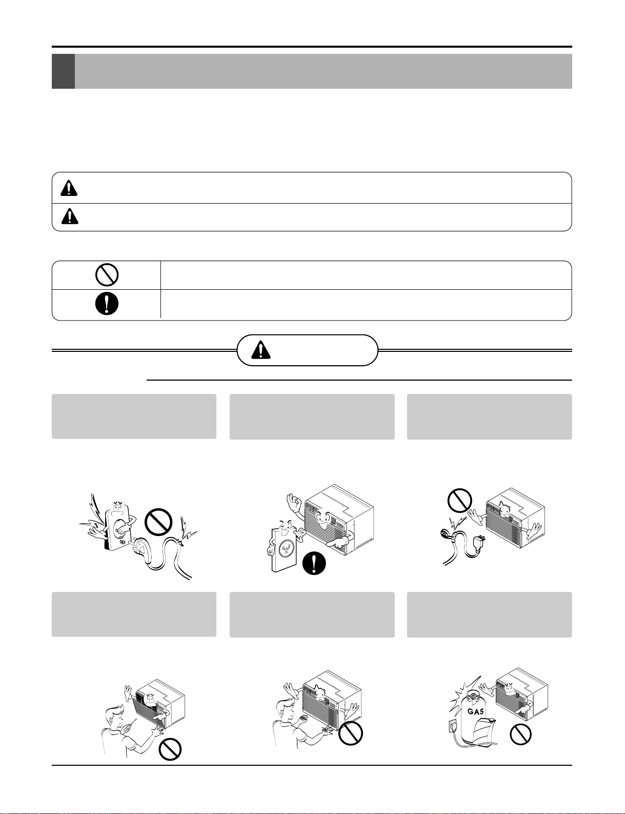
WARNING
■ Installation
Don’t use a power cord, a plug
or a loose socket which is damaged.
• Otherwise, it may cause a fire or
electrical shock.
Always plug into a gr ounded
outlet.
• Otherwise, it may cause a fire or
electrical shock.
Do not modify or extend the
power cord length.
• It will cause electric shock or fire
due to heat generation.
Do not disassemble or modify
products.
• It may cause failure and electric
shock.
Be caution when unpacking and
installing.
• Sharp edges may cause injury.
Do not use the power cord near flammable gas or combustibles such as
gasoline, benzene, thinner, etc.
• It may cause explosion or fire.
Be sure not to do.
Be sure to follow the instruction.
M
O
D
E
T
I
M
E
R
P
O
W
E
R
F
A
N
S
P
E
E
D
F
a
n
H
e
a
t
E
n
e
r
g
y
S
a
v
e
r
C
o
o
l
T
i
m
e
r
T
E
M
P
'
F
F
1
L
O
W
F
2
H
I
G
H
M
O
D
E
T
I
M
E
R
P
O
W
E
R
F
A
N
S
P
E
E
D
F
a
n
H
e
a
t
E
n
e
r
g
y
S
a
v
e
r
C
oo
l
T
im
er
T
E
M
P
'
F
F
1
L
O
W
F
2
H
IG
H
M
O
D
E
T
I
M
E
R
P
O
W
E
R
F
A
N
S
P
E
E
D
F
a
n
H
e
a
t
E
n
e
r
g
y
S
a
v
e
r
C
o
o
l
T
i
m
e
r
T
E
M
P
'
F
F
1
L
O
W
F
2
H
I
G
H
M
O
D
E
T
I
M
E
R
P
O
W
E
R
F
A
N
S
P
E
E
D
F
a
n
H
e
a
t
E
n
e
r
g
y
S
a
v
e
r
C
o
o
l
T
i
m
e
r
T
E
M
P
'
F
F
1
L
O
W
F
2
H
IG
H
Gasolin
M
O
D
E
T
I
M
E
R
P
O
W
E
R
F
A
N
S
P
E
E
D
F
a
n
H
e
a
t
E
n
e
r
g
y
S
a
v
e
r
C
o
o
l
T
i
m
e
r
T
E
M
P
'
F
F
1
L
O
W
F
2
H
I
G
H
4 Room Air Conditioner
Safety Precautions
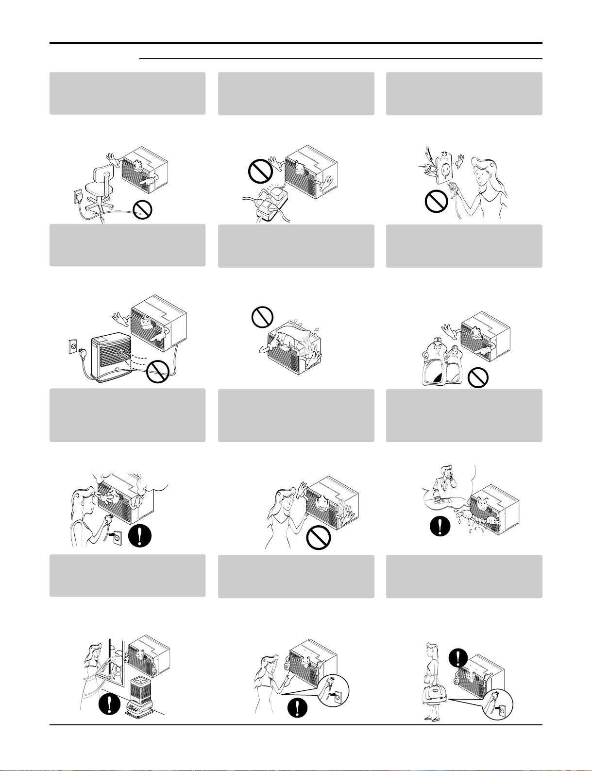
■ Operation
Do not place heavy object on the
power cord and take care so that
the cord should not be pressed.
• There is danger of fire or electric
shock.
Do not share the outlet with
other appliances.
• It will cause electric shock or fire
due to heat generation.
Take the power plug out if necessary, holding the head of the plug
and do not touch it with wet hands.
• Otherwise, it may cause a fire or
electrical shock.
Do not place the power cord
near a heater.
• It may cause fire and electric
shock.
Do not allow water to run into
electric parts.
• It will cause failure of machine or
electric shock.
Use a soft cloth to clean. Do not
use wax, thinner, or a strong
detergent.
• The appearance of the air conditioner may deteriorate, change
color, or develop surface flaws.
Unplug the unit if strange
sounds, odors, or smoke come
from it.
• Otherwise it may cause fire and
electric shock accident.
Do not open the suction inlet
grill of the product during operation.
• Otherwise, it may electrical
shock and failure.
If water enters the product, turn off the the
power switch of the main body of appliance.
Contact service center after taking the
power-plug out from the socket.
Ventilate the room well when
using this appliance together
with a stove, etc.
• An oxygen shortage may occur.
Turn off the power and breaker
firstly when cleansing the unit.
• Since the fan rotates at high speed
during operation, it may cause
injury.
Turn off the main power switch
when not using it for a long
time.
• Prevent accidental startup and the
possibility of injury.
M
O
D
E
T
I
M
E
R
P
O
W
E
R
F
A
N
S
P
E
E
D
F
a
n
H
e
a
t
E
n
e
r
g
y
S
a
v
e
r
C
o
o
l
T
i
m
e
r
T
E
M
P
'
F
F
1
L
O
W
F
2
H
I
G
H
M
O
D
E
T
I
M
E
R
P
O
W
E
R
F
A
N
S
P
E
E
D
F
an
H
e
a
t
E
n
e
r
g
y
S
a
v
e
r
C
o
o
l
T
i
m
e
r
T
E
M
P
'
F
F
1
L
O
W
F
2
H
I
G
H
M
O
D
E
T
I
M
E
R
P
O
W
E
R
F
A
N
S
P
E
E
D
F
a
n
H
e
a
t
E
n
e
r
g
y
S
a
v
e
r
C
o
o
l
T
i
m
e
r
T
E
M
P
'
F
F
1
L
O
W
F
2
H
I
G
H
M
O
D
E
T
I
M
E
R
P
O
W
E
R
F
A
N
S
P
E
E
D
F
a
n
H
e
a
t
E
n
e
r
g
y
S
a
v
e
r
C
o
o
l
T
i
m
e
r
T
E
M
P
'
F
F
1
L
O
W
F
2
H
I
G
H
Wax
Thinner
MODE
TI
M
E
R
POW
E
R
F
A
N
S
P
E
E
D
F
a
n
H
e
a
t
E
n
e
r
g
y
S
a
v
e
r
C
o
o
l
T
i
m
e
r
T
E
M
P
'
F
F
1
L
O
W
F
2
H
I
G
H
M
O
D
E
T
I
M
E
R
P
O
W
E
R
FA
N
SP
E
ED
F
a
n
H
e
a
t
E
n
e
r
g
y
S
a
v
e
r
C
o
o
l
T
i
m
e
r
T
E
M
P
'
F
F
1
L
O
W
F
2
H
I
G
H
M
O
D
E
T
I
M
E
R
P
O
W
E
R
F
A
N
S
P
E
E
D
F
a
n
H
e
a
t
E
n
e
r
g
y
S
a
v
e
r
C
o
o
l
T
i
m
e
r
T
E
M
P
'
F
F
1
L
O
W
F
2
H
I
G
H
M
O
D
E
T
I
M
E
R
P
O
W
E
R
F
A
N
S
P
E
E
D
Fa
n
He
a
t
E
n
e
r
g
y
S
a
v
e
r
Co
ol
Ti
mer
T
E
M
P
'
F
F
1
L
O
W
F
2
H
I
G
H
M
O
D
E
T
I
M
E
R
P
O
W
E
R
F
A
N
S
P
E
E
D
F
a
n
H
e
a
t
E
n
e
r
g
y
S
a
v
e
r
C
o
o
l
T
i
m
e
r
T
E
M
P
'
F
F
1
L
O
W
F
2
H
I
G
H
M
O
D
E
T
I
M
E
R
P
O
W
E
R
F
A
N
S
P
E
E
D
F
a
n
H
e
a
t
E
n
e
r
g
y
S
a
v
e
r
C
o
o
l
T
im
e
r
T
E
M
P
'
F
F
1
L
O
W
F
2
H
I
G
H
M
O
D
E
T
I
M
E
R
P
O
W
E
R
F
A
N
S
P
E
E
D
F
a
n
H
e
at
E
ne
r
g
y
S
av
er
C
o
o
l
T
im
e
r
T
E
M
P
'
F
F
1
L
O
W
F
2
H
I
G
H
Service Manual 5
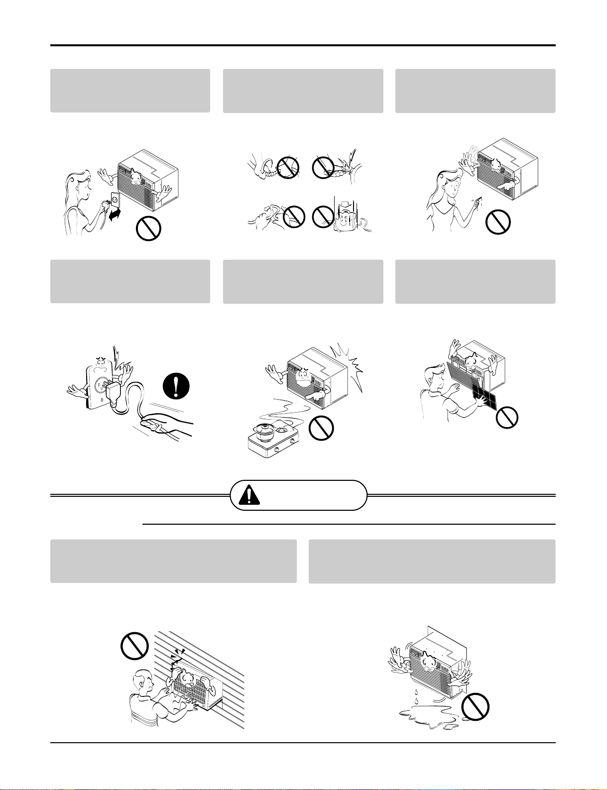
Safety Precautions
Do not operate or stop the unit
by inserting or pulling out the
power plug.
• It will cause electric shock or fire
due to heat generation.
Do not damage or use an
unspecified power cord.
• It will cause electric shock or fire.
Do not operate with wet hands
or in damp environment.
• It will cause electric shock.
Hold the plug by the head when
taking it out.
• It may cause electric shock and
damage.
When gas leaks, open the window for ventilation before operating the unit.
• Otherwise, it may cause explosion, and a fire.
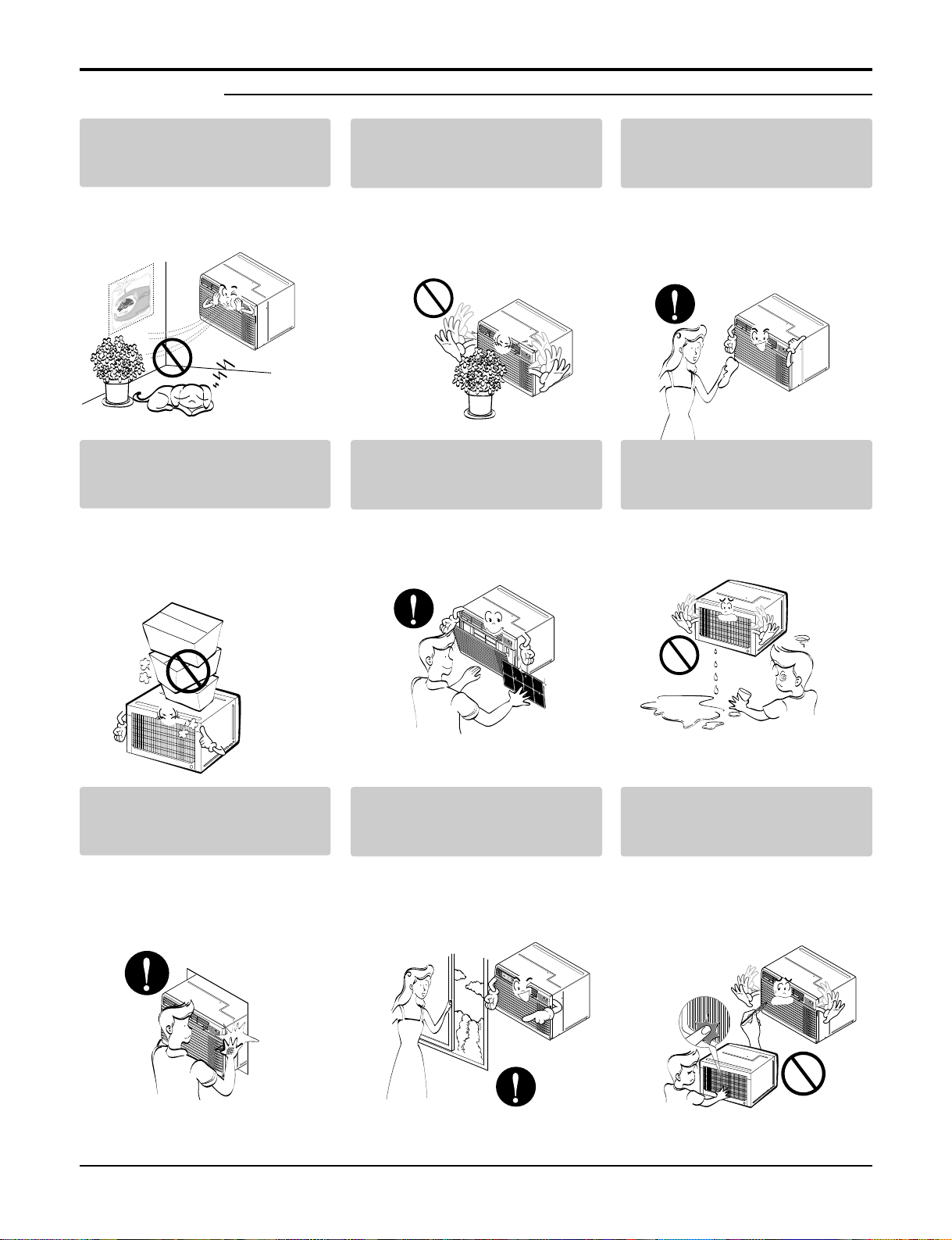
Never touch the metal parts of
the unit when removing the filter.
• They are sharp and may cause
injury.
Install the product so that the noise or hot wind
from the outdoor unit may not cause any damage
to the neighbors.
• Otherwise, it may cause dispute with the neighbors.
Keep level parallel in installing the product.
• Otherwise, it may cause vibration or water leakage.
M
O
D
E
T
I
M
E
R
P
O
W
E
R
F
A
N
S
P
E
E
D
F
a
n
H
e
a
t
E
n
e
r
g
y
S
a
v
e
r
C
o
o
l
T
i
m
e
r
T
E
M
P
'
F
F
1
L
O
W
F
2
H
I
G
H
M
O
D
E
T
I
M
E
R
P
O
W
E
R
F
A
N
S
P
E
E
D
F
a
n
H
e
a
t
E
n
e
r
g
y
S
a
v
e
r
C
o
o
l
T
i
m
e
r
T
E
M
P
'
F
F1
L
OW
F
2 H
IG
H
M
O
D
E
T
I
M
E
R
P
O
W
E
R
F
A
N
S
P
E
E
D
F
a
n
H
e
a
t
E
n
e
r
g
y
S
a
v
e
r
C
o
o
l
T
i
m
e
r
TE
M
P
'
F
F
1
L
O
W
F
2
H
I
G
H
M
O
D
E
T
I
M
E
R
P
O
W
E
R
F
A
N
S
P
E
E
D
F
a
n
H
e
a
t
E
n
e
r
g
y
S
a
v
e
r
C
o
o
l
T
i
m
e
r
T
E
M
P
'
F
F
1 L
OW
F
2 H
IG
H
M
O
D
E
T
I
M
E
R
P
O
W
E
R
F
AN
SP
E
E
D
F
a
n
H
e
a
t
E
n
e
r
g
y
S
a
v
e
r
C
o
o
l
T
i
m
e
r
T
E
M
P
'
F
F
1 L
O
W
F
2
HI
G
H
CAUTION
■ Installation
6 Room Air Conditioner
Safety Precautions
Do not put a pet or house plant
where it will be exposed to
direct air flow.
• It may cause injury.
Do not block the inlet or outlet
of air flow.
• It may cause product failure.
Use a soft cloth to clean. Do not
use wax, thinner, or a strong
detergent.
• The appearance of the air condi-
tioner may deteriorate, change
color, or develop surface flaws.
Do not step on the indoor/outdoor unit and do not put anything on it.
• It may cause an injury through
dropping of the unit or falling
down.
Always insert the filter securely.
Clean it every two weeks.
• Operation without filters will cause
failure.
Do not drink water drained from
air conditioner.
• It contains containments and will
make you sick.
Be cautious not to touch the
sharp edges when installing.
• It may cause injury.
Avoid excessive cooling and
perform ventilation sometimes.
• Otherwise, it may do harm to
your health.
Do not insert the hands or bars
through the air inlet or outlet
during operation.
• Otherwise, it may cause personal injury.
■ Operation
M
O
D
E
T
I
M
E
R
P
O
W
E
R
F
A
N
S
P
E
E
D
F
a
n
H
e
a
t
E
n
e
r
g
y
S
a
v
e
r
C
o
o
l
T
i
m
e
r
T
E
M
P
'
F
F1
LOW
F2
HI
GH
M
O
D
E
T
I
M
E
R
P
O
W
E
R
F
AN
S
PE
E
D
F
a
n
H
e
a
t
E
n
e
r
g
y
S
a
v
e
r
C
o
o
l
T
i
m
e
r
T
E
M
P
'
F
F1 L
O
W
F2
H
I
G
H
M
O
D
E
T
I
M
E
R
P
O
W
E
R
FA
N
S
P
E
E
D
F
a
n
H
e
a
t
E
n
e
r
g
y
S
a
v
e
r
C
o
o
l
T
i
m
e
r
T
E
M
P
'
F
F
1
L
O
W
F2
HI
GH
M
O
D
E
T
I
M
E
R
P
O
W
E
R
F
A
N
S
P
E
E
D
F
a
n
H
e
a
t
E
n
e
r
g
y
S
a
v
e
r
C
o
o
l
T
im
e
r
T
E
M
P
'
F
F
1
L
O
W
F
2
H
I
G
H
M
O
D
E
T
I
M
E
R
P
O
W
E
R
F
A
N
S
P
E
E
D
F
a
n
H
e
a
t
E
n
e
r
g
y
S
a
v
e
r
C
o
o
l
T
i
m
e
r
T
E
M
P
'
F
F1
L
O
W
F
2
H
I
G
H
M
O
D
E
T
I
M
E
R
P
O
W
E
R
F
A
N
S
P
E
E
D
F
a
n
H
e
a
t
E
n
e
r
g
y
S
a
v
e
r
C
o
o
l
T
i
m
e
r
T
E
M
P
'
F
F
1
L
O
W
F
2
H
I
G
H
M
O
D
E
T
I
M
E
R
P
O
W
E
R
F
A
N
S
P
E
E
D
F
a
n
H
e
a
t
E
n
e
r
g
y
S
a
v
e
r
C
o
o
l
T
i
m
e
r
T
E
M
P
'
F
F
1 L
OW
F
2 H
IG
H
Service Manual 7
Installation
Installation
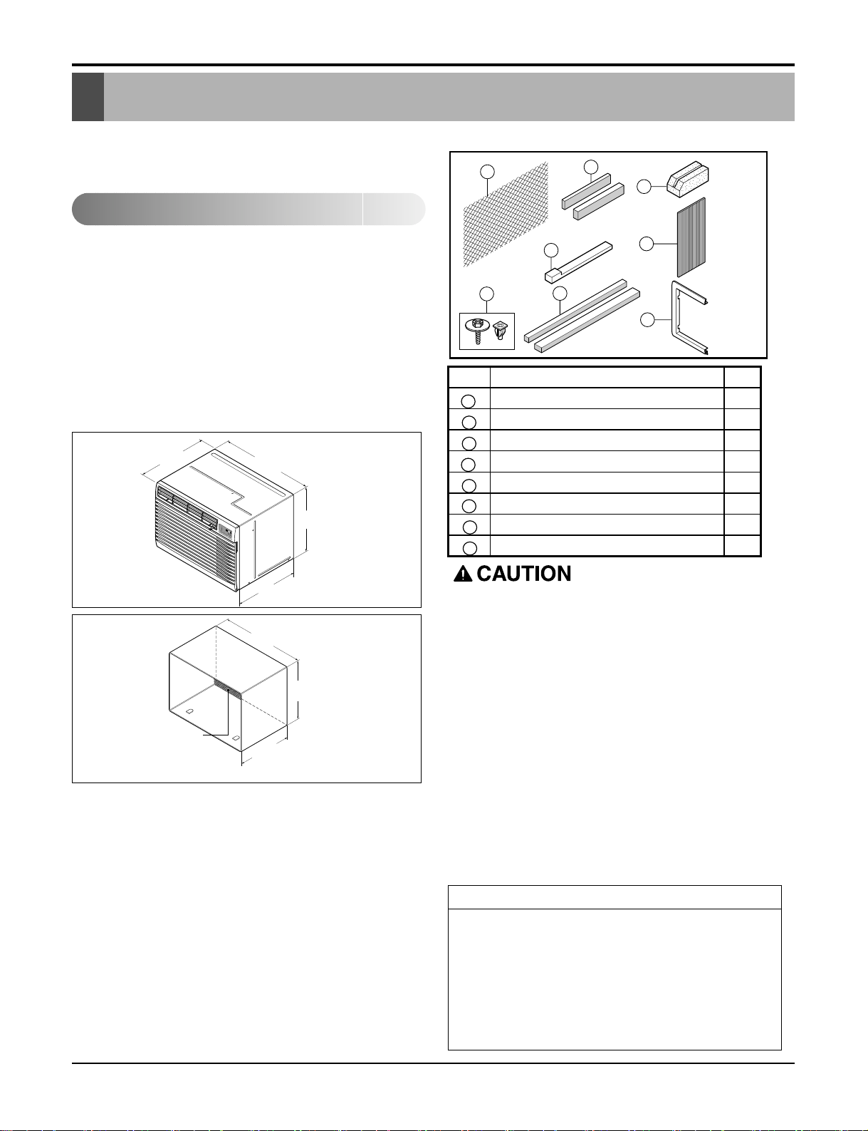
Remove packing sheet from the back of the sleeve,
and packing corner and blue tape from the air conditioner.
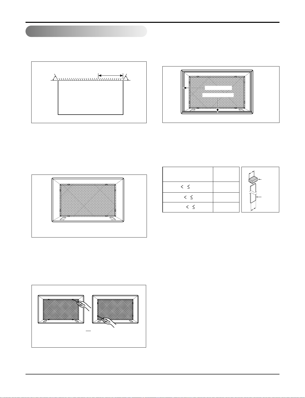
If you use an existing wall sleeve, you should measure its dimensions.
Install the new air conditioner according to these installation instructions to achieve the best performance.
All wall sleeves used to mount the new air conditioner
must be in good structural condition and have a rear
grille to securely attach the new air conditioner.
(FIG. 1)
With the LGE sleeve(optionally supplied with your
unit), you can maintain the best performance of the
new air conditioner. (FIG. 2)
ELECTRICAL SERVICE
Check your available electrical service. The power
supply available must be the same as that shown on
the unit nameplate (found on left side of cabinet).
All models are equipped with a 3-prong service plug to
provide proper service and safe positive grounding. Do
not change plug in any way. Do not use an adapter
plug. If your present wall outlet does not match your
plug, call a qualified electrician to make the necessary
corrections. SAVE CARTON for storage and this
OWNER'S MANUAL for future reference. The carton is
the best way to store unit during winter or when not in
use.
INSTALLATION HARDWARE
14-13/32"
(366 mm)
24-21/32"
(626 mm)
18"(458 mm)
19-
21
/32"
(499 mm)
M
O
D
E
T
I
M
E
R
P
O
W
E
R
F
A
N
S
P
E
E
D
F
a
n
H
e
a
t
E
n
e
r
g
y
S
a
v
e
r
C
o
o
l
T
i
m
e
r
TEM
P
'
F
F
1
L
O
W
F
2
H
I
G
H
To avoid risk of personal injury, property damage, or
product damage due to the weight of this device and
sharp edges that may be exposed:
• Air conditioners covered in this manual pose an
excessive weight hazard. Two or more people are
needed to move and install the unit.
To prevent injury or strain, use proper lifting and
carrying techniques when moving unit.
• Carefully inspect location where air conditioner will
be installed. Be sure it will support the weight of the
unit over an extended period of time.
• Handle air conditioner with care. Wear protective
gloves whenever lifting or carrying the unit. AVOID
the sharp metal fins of front and rear coils.
• Make sure air conditioner does not fall during installation.
REQUIRED TOOLS:
• Tight Fitting gloves
• Standard screwdriver
• Phillips screwdriver
• Pliers
• Sharp knife
• 3/8-inch open end
wrench or adjustable
wrench
• 1/4-inch hex socket and
ratchet
• Tape measure
• Electric drill
• 1/4-inch drill bit
FIG. 1
Air Conditioner
FIG. 2
LGE Wall Sleeve
Installation requirements
1
2
4
2 Size options
7
8
3
5
6
2 Size options
ITEM NAME OF PARTS Q'TY
1 PLASTIC GRILLE 1
2 HORIZONTAL INSULATION STRIPS 2
3 AROUND INSULATION STRIPS 2
4 SUPPORT BLOCK 2
5 BAFFLE 1
6 TRIM FRAME 2
7 SHIM 2
8 PLASTIC NUTS AND WASHER SCREWS 4
Expanded
aluminum metal grille
25-7/8"
(656 mm)
16-23/32"
(425 mm)
15-17/32"
(394 mm)
• Pick a location which will allow the conditioned air to
blow into the area you want. Good installation with
special attention to the proper position of the unit will
lessen the chance that service will be needed.
ITEMS IN INSTALLATION HARDWARE
You may not need all parts in the kit. Discard unused
parts
1. Identify the existing wall sleeve before installing the
unit from the listed below.
All wall sleeves used to mount the new Air
Conditioner must be in sound structural condition and
have a rear grille that securely attaches to sleeve, or
rear flange that serves as a stop for the Air
Conditioner,
2. Remove old air conditioner from existing wall
sleeve.
3. Clean the interior of an existing sleeve.
(Do not disturb seals.)
4. Wall sleeve must be securely fastened in wall
before installing the air conditioner. Use the nails or
screws through sleeve into wall, if needed. Repaint
sleeve if needed.
5. Prepare the wall sleeve for installation of the unit. If
you plan to use your existing wall sleeve, and it is
not LGE, use procedure B or C below.
6. Install new unit into wall sleeve.
When installation is completed, replacement unit
MUST have a rearward slope as shown. To achieve
1/4" slope, remove the backing from the 11-13/16"
shim strips and attach them as shown below in Fig. 3.
Place the higher portion of shim to the front of the rib
on base of wall sleeve.
NOTICE
8 Room Air Conditioner
Installation
Installation
How to Install
We strongly recommend the removal of the old wall
sleeve and the installation of a new LGE Wall Sleeve.
If you decide to keep the existing wall sleeve, you have
to redirect the louvers at the back of the wall sleeve illustration. The use of pliers is recommended. If you DO
NOT redirect, you run the risk of poor performance or
product failure. This is not covered under the terms of the
LGE warranty.
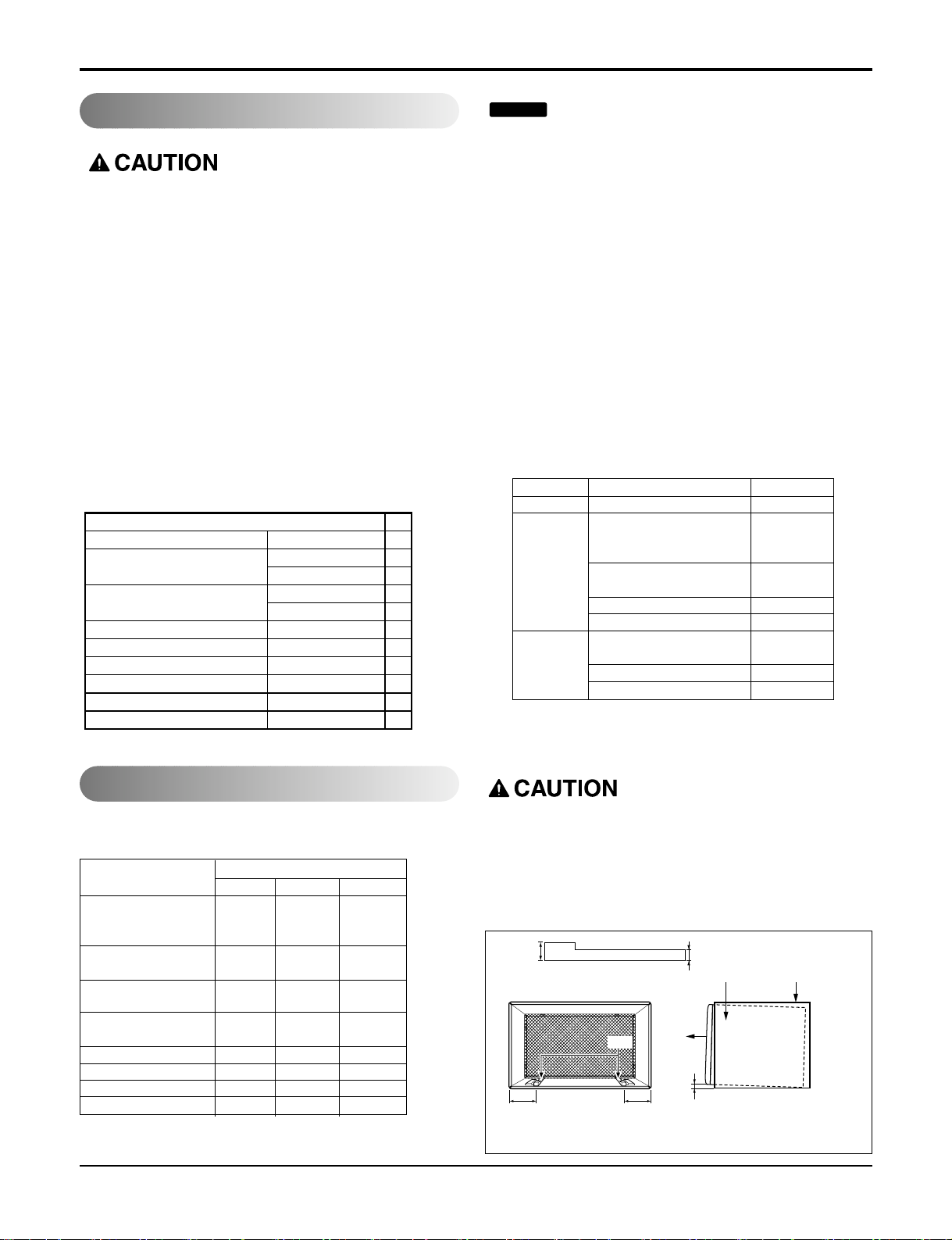
Wall Sleeve Dimensions (inches)
Brand
Width Height Depth
White-Westinghouse
25-1/2 15-1/4
16, 17-1/2
Frigidaire
or 22
Carrier (52F series)
General Electric
26 15-5/8 16-7/8
/Hotpoint
Whirlpool 25-7/8 16-1/2
17-1/8
or 23
Fedders/Emerson 27 16-3/4
16-3/4
or 19-3/4
LGE 25-7/8 15-17/32 16-23/32
Emerson/Fedders 26-3/4 15-3/4 15
Carrier (51S Series) 25-3/4 16-7/8 18-5/8
Friedrich 27 16-3/4 16-3/4
Procedure Brand
Depth(inches)
A LGE 16-23/32
White-Westinghouse
Frigidaire Carrier
16, 17-1/2
(52F series)
or 22
B
General Electric
16-7/8
/Hotpoint
Whirlpool 17-1/8 or 23
Carrier (51S series)
18-5/8
Fedders/Emerson
16-3/4
or 19-3/4
C
Emerson/Fedders 15
Friedrich 16-3/4
1/4"
Wall Sleeve
FRONT
UNIT
SHIM PLACEMENT UNIT INSTALLATION
1" high
3
/4" High
Shim
6" 6"
FIG. 3
ITEM (inches)
Plastic grille 263/4 x 161/2 1
Horizontal Insulation Strips
Around Insulation Strips
Support Block 13/4 x 1 3/8 x 45/16 2
Baffle 14 x 41/2 x 1/8 1
Shim 13 x 1 x 3/4 2
Trim Frame 2
Washer Screw 4
Nuts(Plastic) 4
13/8 x 5/8 x 273/16 1
13/8 x 1 3/8 x 27 3/16 1
13/8 x 3/4 x 611/2 1
13/8 x 1 3/8 x 61 1/2 1
Qty.
Service Manual 9
Installation
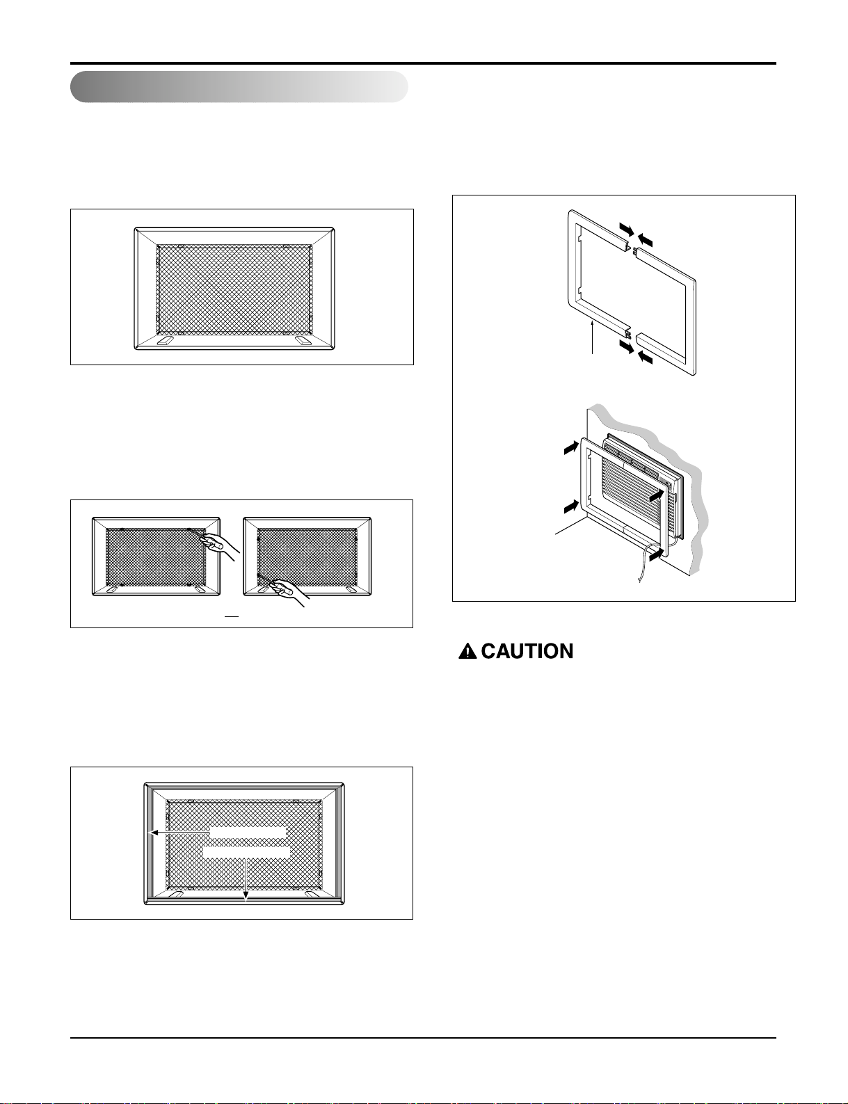
Procedure A
1. If you are using the new sleeve (optionally supplied
with your unit),skip to step 3. Otherwise, install the
plastic grille from the kit. Cut the plastic grille to 251/2" wide and 15-1/4" high. Place the plastic grille to
the inside of the wall sleeve at the rear flange.
2. Fasten the 4 washer screws to secure the grille to
the wall sleeve. If you need plastic nuts to mount
plastic grille to the inside of the wall sleeve, there
are plastic nuts in the installation kit. The nuts are
installed from the inside of the sleeve and are
pressed into the square holes of the rear flanges.
3. Remove the backing from the Horizontal Insulation
strip 1
3
/
8
x
3
/
8
8 x 27
3
/
16
and attach that to the inside
bottom of the sleeve as shown below. Remove the
backing from the Around Insulation strip 1
3
/
8
x
3
/
4
x
61
1
/
2
and attach that to the inside front of the sleeve
as shown below.
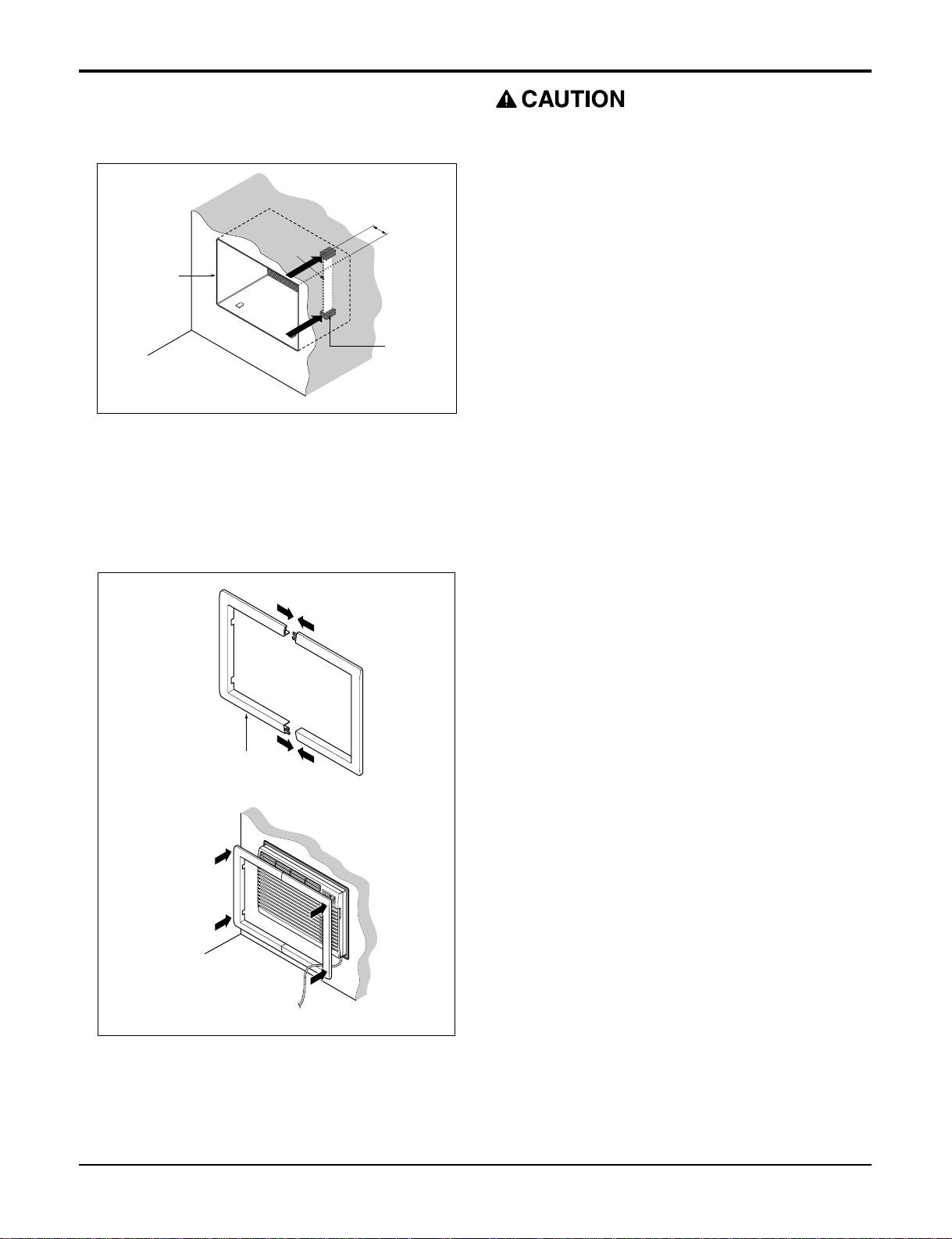
4. Install the new unit into the wall sleeve.
FIG. 4
Around Insulation
Horizontal Insulation
FIG. 6
or
FIG. 5
Wall
Trim (2 ea)
M
O
D
E
T
I
M
E
R
P
O
W
E
R
F
A
N
S
P
E
E
D
F
a
n
H
e
a
t
E
n
e
r
g
y
S
a
v
e
r
C
o
o
l
T
i
m
e
r
T
E
M
P
'
F
F
1
L
O
W
F
2
H
I
G
H
• Air conditioners covered in this manual pose an
excessive weight hazard. Two or more people are
needed to move and install the unit.
To prevent injury or strain, use proper lifting and
carrying techniques when moving unit.
• When handling the air conditioner, be careful to
avoid cuts from sharp metal fins on front and rear
coils.
• Make sure air conditioner does not fall during
removal.
FIG. 7
5. To assemble trim, snap the tab of each piece into
the slot of the other piece as shown below. Slide
trim over the front of the air conditioner until trim is
flush with sleeve as shown below.
10 Room Air Conditioner
Installation
Procedure B
1. Redirect the louvers at the back of the wall sleeve to
60° angle as shown in the FIG 8. The use of pliers is
recommended.
2. If the wall sleeve already has a rear grille, skip to
step 4. If the wall sleeve does not have a rear grille
or louvered panel, install the plastic grille from the
kit. Cut the plastic grille to 25-1/2" wide and 15-1/4"
high. Place the plastic grille to the inside of the wall
sleeve at the rear flange.
3. Fasten the 4 washer screws to secure the grille to
the wall sleeve. If you need plastic nuts to mount
plastic grille to the inside of the wall sleeve, there
are plastic nuts in the installation kit. The nuts are
installed from the inside of the sleeve and are
pressed into the square holes of the rear flanges.
4. Remove the backing from the Horizontal Insulation
strip 1
3
/
8
x
5
/
8
x 27
3
/
16
and attach that to the inside bottom of the sleeve as shown below. Remove the
backing from the Around Insulation strip 1
3
/
8
x
3
/
4
x
61
1
/
2
and attach that to the inside front of the sleeve
as shown below.
5.If the depth of your existing wall sleeve is less than
or equal to 18", skip to step 6. Otherwise, cut the
baffles and the support blocks according to length
Rear Louvers
(Top View)
60°
60°
7
5
/
16
"
FIG. 8
FIG. 9
Place the plastic grille
or
FIG. 10
Fasten the screws
Around Insulation
Horizontal Insulation
FIG. 11
Depth"D" of the existing
wall sleeve (inches)
Length "A"
(inches)
Support
Block
Baffle
A
A
3
/4
1-3/4
4
18 D 18-5/
8
18-5/
8
D 19-3/
4
19-3/4 D 22
FIG. 12
"A" in the table below.
Service Manual 11
Installation
6. Remove the backing from the support blocks and
attach them to the inside of the wall sleeve as
shown FIG 13. Slide the baffle into slots of the support blocks.
7.Install the new unit into the wall sleeve.
8.To assemble trim, snap the tab of each piece into the
slot of the other piece as shown below. Slide trim
over the front of the air conditioner until trim is flush
with sleeve as shown below.
Wall
Wall
Sleeve
Baffle
(7
5
/
16
")
Front
Support
Block
FIG. 13
Wall
Trim (2 ea)
M
O
D
E
T
I
M
E
R
P
O
W
E
R
F
A
N
S
P
E
E
D
F
a
n
H
e
a
t
E
n
e
r
g
y
S
a
v
e
r
C
o
o
l
T
i
m
e
r
T
E
M
P
'
F
F
1
L
O
W
F
2
H
I
G
H
FIG. 14
• Air conditioners covered in this manual pose an
excessive weight hazard. Two or more people are
needed to move and install the unit.
To prevent injury or strain, use proper lifting and
carrying techniques when moving unit.
• When handling the air conditioner, be careful to
avoid cuts from sharp metal fins on front and rear
coils.
• Make sure air conditioner does not fall during
removal.
 Loading...