

Page 1

System
Indoor Unit (2 Series)
INSTALLATION MANUAL
LG
Type: Ceiling Concealed Duct - High Static
IMPORTANT
• Please read this installation manual completely before
installing the product.
• Installation work must be performed in accordance with
the national wiring standards by authorized personnel
only.
• Please retain this installation manual for future reference
after reading it thoroughly.
ENGLISH FRANÇAIS ESPAÑOL
Page 2
2 Indoor Unit
IMPORTANT!
CAUTION
: Improper installation, adjustment, alteration, service or maintenance can void the warranty.
The weight of the condensing unit requires caution and proper handling procedures when lifting
or moving to avoid personal injury. Use care to avoid contact with sharp or pointed edges.
Safety Precautions
• Always wear safety eye wear and work gloves when installing equipment.
• Never assume electrical power is disconnected. Check with meter and equipment.
• Keep hands out of fan areas when power is connected to equipment.
• R-410A causes frostbite burns.
• R-410A is toxic when burned.
NOTE TO INSTALLING DEALER: The Owners Instructions and Warranty are to be given to the owner
or prominently displayed near the indoor Furnace/Air Handler Unit.
When wiring:
Electrical shock can cause severe personal injury or death. Only a qualified,
experienced electrician should attempt to wire this system.
• Do not supply power to the unit until all wiring and tubing are completed or reconnected and checked.
• Highly dangerous electrical voltages are used in this system. Carefully refer to the wiring diagram and these
instructions when wiring. Improper connections and inadequate grounding can cause accidental injury or death.
• Ground the unit following local electrical codes.
• Connect all wiring tightly. Loose wiring may cause overheating at connection points and a possible fire hazard.
When transporting:
Be careful when picking up and moving the indoor and outdoor units. Get a partner to help, and
bend your knees when lifting to reduce strain on your back. Sharp edges or thin aluminum fins on
the air conditioner can cut your finger.
When installing...
... in a wall: Make sure the wall is strong enough to hold the unit's weight.
It may be necessary to construct a strong wood or metal frame to provide added support.
... in a room: Properly insulate any tubing run inside a room to prevent "sweating" that can cause
dripping and water damage to wall and floors.
... in moist or uneven locatinons: Use a raised concrete pad or concrete blocks provide a solid,
level foundation for the outdoor unit. This prevents water damage and abnormal vibration.
... in an area with high winds: Securely anchor the outdoor unit down with bolts and a metal
frame. Provide a suitable air baffle.
... in a snowy area(for Heat Pump Model): Install the outdoor unit on a raised platform that is
higher than drifting snow. Provide snow vents.
When connecting refrigerant tubing
• Keep all tubing runs as short as possible.
• Use the flare method for connecting tubing.
• Check carefully for leaks before starting the test run.
When servicing
• Turn the power OFF at the main power box(mains) before opening the unit to check or repair
electrical parts and wiring.
• Keep your fingers and clothing away from any moving parts.
• Clean up the site after you finish, remembering to check that no metal scraps or bits of wiring have
been left inside the unit being serviced.
Special warnings
WARNING
• Installation or repairs made by unqualified persons can result in hazards to you and others.
Installation MUST conform with local building codes or, in the absence of local codes, with the National Electrical
Code NFPA 70/ANSI C1-1993 or current edition and Canadian Electrical Code Part1 CSA C.22.1.
• The information contained in the manual is intended for use by a qualified service technician familiar with safety
procedures and equipped with the proper tools and test instruments.
• Failure to carefully read and follow all instructions in this manual can result in equipment malfunction, property
damage, personal injury and/or death.
Please read this instruction sheet completely before installing the product.
This air conditioning system meets strict safety and operating standards. As the installer or service person,
it is an important part of your job to install or service the system so it operates safely and efficiently.
Page 3

Installation Manual 3
ENGLISH
Ceiling Concealed Duct - High Static Type Indoor Unit Installation Manual
TABLE OF CONTENTS
❏ Four type "A" screws
❏ Connecting cable
❏ Pipes: Gas side
Liquid side
(Refer to Product Data)
❏ Insulation materials
❏ Additional drain pipe
❏ Level gauge
❏ Screw driver
❏ Electric drill
❏ Hole core drill
❏ Flaring tool set
❏ Specified torque wrenches
(different depending on model No.)
❏ Spanner .......Half union
❏ A glass of water
❏ Screw driver
❏ Hexagonal wrench
❏ Gas-leak detector
❏ Vacuum pump
❏ Gauge manifold
❏ Owner's manual
❏ Thermometer
Features ...................................4
Safety Precautions.................5
Installation
Selection the best location ....8
Ceiling opening dimension
and hanging bolt location ......9
Indoor Unit Installation.........10
Wiring Connection ...............10
Checking the Drainage........11
Installation of Remote con-
troller.....................................14
Optional Operation of Wired
Remote Controller ...............16
Dip Switch Setting ...............17
Group Control Setting..........18
How to Set E.S.P? ................21
Installation Requirements
Required Parts Required Tools
Page 4
4 Indoor Unit
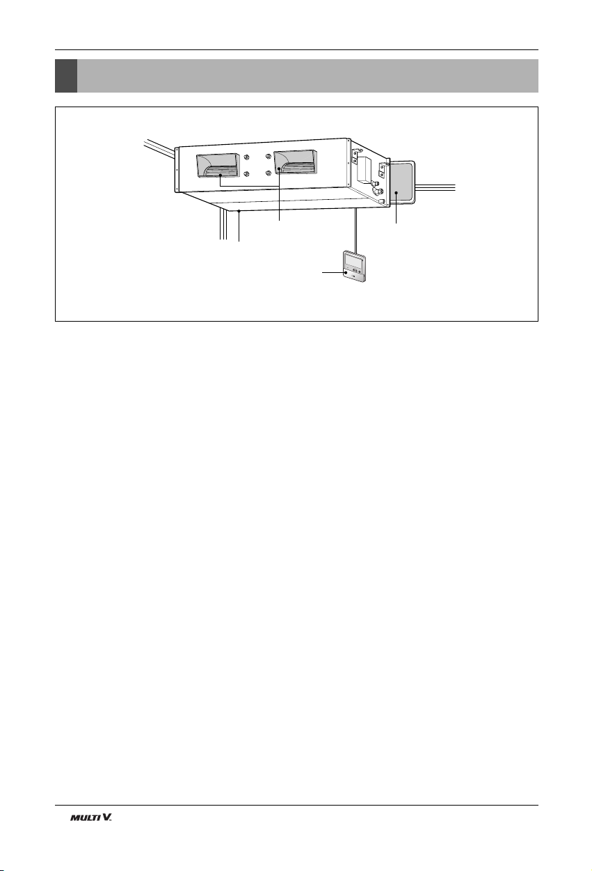
Feature
Air filters
Wired Remote Controller
Air intake vents
Air outlet vents
R
e
mo
t
e C
on
tro
lle
r
T
E
M
P
Features
Page 5
Installation Manual 5
ENGLISH
Safety Precautions
Safety Precautions
To prevent injury to the user or other people and property damage, the following instructions must be followed.
■ Be sure to read before installing the air conditioner.
■ Be sure to observe the cautions specified here as they include important items related to safety.
■ Incorrect operation due to ignoring instruction will cause harm or damage. The seriousness is classified by the
following indications.
■ Meanings of symbols used in this manual are as shown below.
This symbol indicates the possibility of death or serious injury.
This symbol indicates the possibility of injury or damage to properties only.
Be sure not to do.
Be sure to follow the instruction.
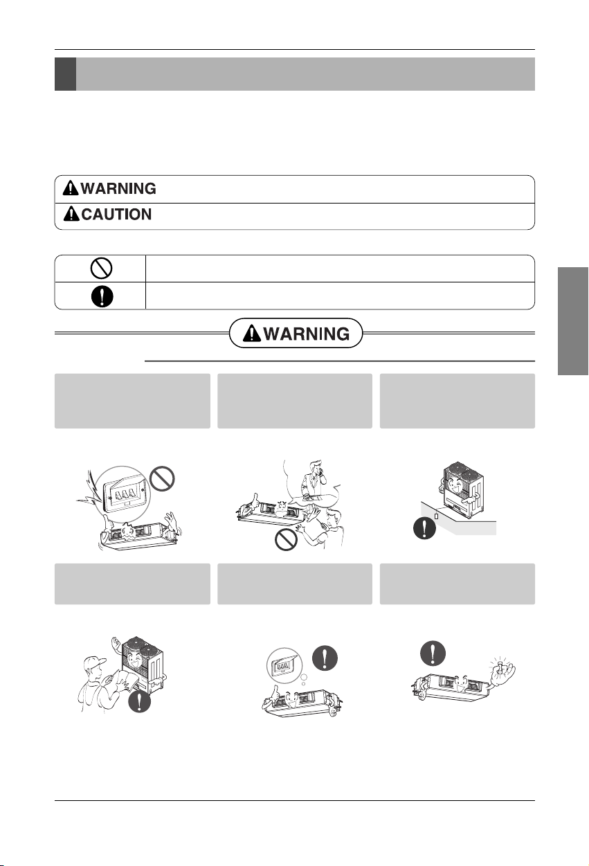
■ Installation
Do not use a defective or underrated circuit breaker. Use this
appliance on a dedicated circuit.
• There is risk of fire or electric shock.
For electrical work, contact the
dealer, seller, a qualified electrician, or an Authorized Service
Center.
• Do not disassemble or repair the
product. There is risk of fire or electric shock.
Always ground the product.
• There is risk of fire or electric shock.
Install the panel and the cover
of control box securely.
• There is risk of fire or electric shock.
Always install a dedicated circuit and breaker.
• Improper wiring or installation may
cause fire or electric shock.
Use the correctly rated breaker
or fuse.
• There is risk of fire or electric shock.
Page 6
6 Indoor Unit
Safety Precautions
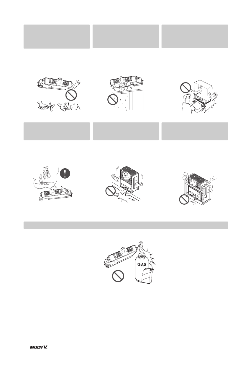
■ Operation
Do not modify or extend the
power cable.
• There is risk of fire or electric shock.
Do not let the air conditioner
run for a long time when the
humidity is very high and a door
or a window is left open.
• Moisture may condense and wet or
damage furniture.
Be cautious when unpacking
and installing the product.
• Sharp edges could cause injury. Be
especially careful of the case edges
and the fins on the condenser and
evaporator.
For installation, always contact
the dealer or an Authorized
Service Center.
• There is risk of fire, electric shock,
explosion, or injury.
Do not install the product on a
defective installation stand.
• It may cause injury, accident, or
damage to the product.
Be sure the installation area
does not deteriorate with age.
• If the base collapses, the air conditioner could fall with it, causing property damage, product failure, and
personal injury.
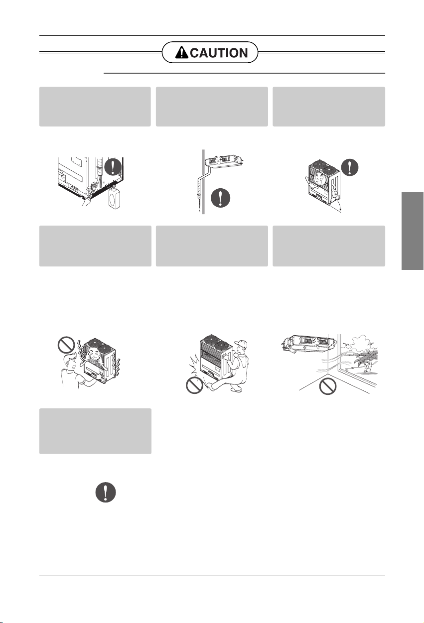
Do not store or use flammable gas or combustibles near the product.
• There is risk of fire or failure of product.
Gasolin
Page 7
Installation Manual 7
ENGLISH
Safety Precautions
Always check for gas (refrigerant) leakage after installation or
repair of product.
• Low refrigerant levels may cause
failure of product.
Install the drain hose to ensure
that water is drained away properly.
• A bad connection may cause water
leakage.
Keep level even when installing
the product.
• To avoid vibration or water leakage.
Do not install the product where
the noise or hot air from the outdoor unit could damage the
neighborhoods.
• It may cause a problem for your
neighbors.
Use two or more people to lift
and transport the product.
• Avoid personal injury.
Do not install the product where
it will be exposed to sea wind
(salt spray) directly.
• It may cause corrosion on the product.
Corrosion, particularly on the condenser and evaporator fins, could
cause product malfunction or inefficient
operation.
■ Installation
If you eat the liquid from the
batteries, brush your teeth and
see doctor. Do not use the
remote if the batteries have
leaked.
• The chemicals in batteries could
cause burns or other health
hazards.
90˚
Page 8
8 Indoor Unit
Installation
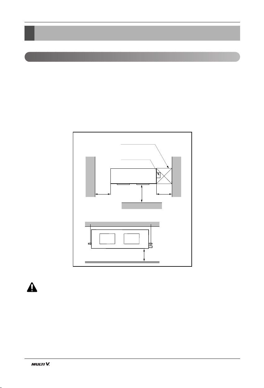
Install the air conditioner in the location that satisfies the following conditions.
• The place shall easily bear a load exceeding four times the indoor unit’s weight.
• The place shall be able to inspect the unit as the figure.
• The place where the unit shall be leveled.
• The place shall allow easy water drainage.(Suitable dimension “H” is necessary to get a slope to drain as
figure.)
• The place shall easily connect with the outdoor unit.
• The place where the unit is not affected by an electrical noise.
• The place where air circulation in the room will be good .
• There should not be any heat source or steam near the unit.
Read completely, then follow step by step.
Top view
H
Front view
600
(23-5/8)
600
(23-5/8)
Front
Inspection hole
[600(23-5/8) x 600(23-5/8)]
Control box
1000
(39-3/8)
Unit:mm(inch)
Installation
Selection of the best location
CAUTION : In case that the unit is installed near the sea, the installation parts
may be corroded by salt, The installation parts (and the unit) should be taken
appropriate anti-corrosion measures.
Page 9

Installation Manual 9
ENGLISH
Installation
■ Installation of Unit
Install the unit above the ceiling correctly.
• Apply a joint-canvas between the unit and duct to
absorb unnecessary vibration.
• Install the unit leaning to a drainage hole side as a fig-
ure for easy water drainage.
• A place where the unit will be leveled and that can
support the weight of the unit.
• A place where the unit can withstand its vibration.
• A place where service can be easily performed.
CASE 1
POSITION OF SUSPENSION BOLT
CASE 2
POSITION OF CONSOLE BOLT
Drainage hole
M10 Nut
M10 SP. washer
M10 washer
X 4
X 4
(Local
supply)
X 4
M10 Nut
M10 SP. washer
M10 washer
X 4
X 4
(Local
supply)
X 4
A
B
CD
(G)
H
I
EF
B8 Chassis
BH/BG/BR Chassis
• Throughly study the following installation locations:
1. In such places as restaurants and kitchens, considerable amount of oil steam and flour adhere to the fan, the fin of the
heat exchanger, resulting in heat exchange reduction, spraying, dispersing of water drops, etc.
In these cases, take the following actions:
• Make sure that the ventilation fan for smoke-collecting hood on a cooking table has sufficient capacity so that it draws oily
steam which should not flow into the suction of the air conditioner.
• Make enough distance from a cooking room to install the air conditioner in such a place where it may not suck in oil
steam.
2. Avoid installing air conditioner in such circumstances where cutting oil mist or iron powder is in suspension in factories, etc.
3. Avoid places where inflammable gas is generated, flows in, is stored or vented.
4. Avoid places where sulfurous acid gas or corrosive gas is generated.
5. Avoid places near high frequency generators.
NOTICE
Ceiling dimension and hanging bolt location
[Unit:mm(inch)]
ABCDEFGH I J KL
B8
1680
(66-1/8)
1565
(61-5/8)
1160
(45-11/16)
330
(12-15/16)
460
(18-1/16)
580
(22-11/13)
700
(27-9/16)
1400
(55-1/8)
1635
(64-5/13)
390
(15-3/8)
445
(17-7/13)15(5/8)
Dimension
Chassis
[Unit:mm(inch)]
A B C D E F (G) H I
BH
BG
BR
Dimension
Chassis
932
(36-9/13)
1232
(48-7/13)
1282
(50-7/16)
882
(34-11/16)
1182
(46-7/13)
1230
(48-5/8)
355
(13-5/8)
355
(13-5/8)
477
(18-13/16)
47
(1-3/4)
47
(1-3/4)
56
(2-3/13)
450
(17-11/16)
450
(17-11/16)
590
(23-3/16)
30
(1-3/16)
30
(1-3/16)
30
(1-3/16)
87
(3-5/8)
87
(3-5/8)
120
(4-9/13)
750
(29-1/2)
830
(32-11/16)
1006
(39-5/8)
158
(6-3/13)
186
(7-5/16)
294
(11-9/16)
Page 10

10 Indoor Unit
Installation
• Select and mark the position for fixing bolts.
• Drill the hole for set anchor on the face of ceiling.
• Insert the set anchor and washer onto the suspension bolts for locking the suspension bolts on the
ceiling.
•
Mount the suspension bolts to the set anchor firmly.
• Secure the installation plates onto the suspension
bolts (adjust level roughly) using nuts, washers
and spring washers.
1 Set anchor
Old building New building
2 Plate washer
3 Spring washer
4 Nut
5 Suspension
bolts
Connect the wires to the terminals on the control board individually according to the outdoor unit connection.
• Ensure that the color of the wires of outdoor unit and the terminal No. are the same as those of indoor unit respectively.
Clamping of cables
1) Arrange 2 power cables on the control panel.
2) First, fasten the steel clamp with a screw to the inner boss of control panel.
3) For the cooling model, fix the other side of the clamp with a screw strongly. For the heat pump model, put the
0.75mm2 cable(thinner cable) on the clamp and tighten it with a plastic clamp to the other boss of the control
panel.
A-- ----BAB
GND 12V
DRY2DRY1
INTERNETIDUSODU
Outdoor
Unit
Terminal Block Indoor
1(L1) 2(L2) 3(A) 4(B)
INDOOR POWER INPUT
Wiring Connection
Indoor Unit Installation
CAUTION : Tighten the nut and bolt
to prevent unit falling.
WARNING : Make sure that the screws of the terminal are free from looseness.
Page 11

Installation Manual 11
ENGLISH
Installation
1. Remove the Air Filter.
2. Check the drainage.
• Spray one or two glasses of water upon the
evaporator.
• Ensure that water flows drain hose of indoor
unit without any leakage.
Checking the Drainage
INSULATION, OTHERS
Insulate the joint and tubes completely.
All thermal insulation must comply with local requirement.
INDOOR UNIT
THERMAL INSULATION
Make sure that there is no clearance here.
Overlap with thermal
insulator for piping.
Thermal insulator for refrigerant pipe
(Local supply)
Thermal insulator for
piping(Local supply)
Hose crip for thermal insulator(Local supply)
Union for liquid pipe
Refrigerant pipe and thermal
insulator(Local supply)
Union for gas pipe
Thermal insulator for refrigerant pipe
(Local supply)
Hose crip for thermal insulator
(Local supply)
WARNING : Loose wiring may cause the terminal to overheat or result in unit
malfunction.
A fire hazzard may also exist.
Therefore, be sure all wiring is tightly connected.
Connection method of the connecting cable(Example)
1(L1) 2(L2)
Power Supply
High Voltage
(208/230V)
3(A)
4(B)
Transmission
Conduit
Lock nut
Conduit
mounting
plate
Page 12

12 Indoor Unit
Installation
Ceiling
CAUTION
1~3mm
(1/128~3/128 inch)
Drainage hole
Drainage hole
U-Trap
B
C
A ≥ 70mm
(2-9/16 inch)
B ≥ 2C
C ≥ 2 x SP
SP = External Pressure
(mmAq)
Ex) External Pressure
= 10mmAq
A ≥ 70mm(2-9/16 inch)
B ≥ 40mm(1-7/12 inch)
C ≥ 20mm(19/24 inch)
A
Make sure to be closed.
Unit
Drainage pipe
(Local supply)
Thermal insulator
(Local supply)
Drainage hole
CAUTION FOR GRADIENT OF
UNIT AND DRAIN PIPING
Lay the drain hose with a downware
inclination so water will drain out.
Front of view
• Alway lay the drain with downward inclination
(1/50 to 1/100).
Prevent any upward flow or reverse flow in any
part.
• 5mm(5/24 inch) or thicker formed thermal insulator shall always be provided for the drain pipe.
CORRECT
• Install the P-Trap (or U-Trap) to prevent
a water leakage caused by the blocking
of intake air filter.
Applied U-Trap Dimension
1. Install declination of the indoor unit is very important for the drain of the duct type air conditioner.
2. Minimum thickness of the insulation for the connecting pipe shall be 5mm.
• The unit must be horizontal or declined to the drain hose connected when finished
installation.
Drain Pump
unuse
INCORRECT
Drain Pump
use
• Upward routing not
allowed
Page 13

Installation Manual 13
ENGLISH
Installation
CAUTION:
After the confirmation of the above conditions, prepare the wiring as follows:
1) Never fail to have an individual power specialized for the air conditioner. As for the method of
wiring, be guided by the circuit diagram posted on the inside of control box cover.
2) Provide a circuit breaker switch between power source and the unit.
3) The screws which fasten the wiring in the casing of electrical fittings are liable to come loose
from vibrations to which the unit is subjected during the course of transportation. Check them
and make sure that they are all tightly fastened. (If they are loose, it could give rise to burn-out
of the wires.)
4) Specification of power source
5) Confirm that electrical capacity is sufficient.
6) Be sure that the starting voltage is maintained at more than 90 percent of the rated voltage
marked on the name plate.
7) Confirm that the cable thickness is as specified in the power sources specification.
(Particularly note the relation between cable length and thickness.)
8) Never fail to equip a leakage breaker where it is wet or moist.
9) The following troubles would be caused by voltage drop-down.
• Vibration of a magnetic switch, damage on the contact point, fuse breaking, disturbance by the nor-
mal function of an overload protection device.
• Proper starting power is not given to the compressor.
HAND OVER
Teach the customer the operation and maintenance procedures, using the operation manual.
(air filter cleaning, temperature control, etc.)
Page 14

14 Indoor Unit
Installation
Installation of Wired Remote Controller
1. Connect the wired remote controller cable
to the wired remote controller installation
board as shown in the right picture.
2. After fixing the cable to the guide slot,
attach the wired remote controller installation board at the desired location.
• Before fixing the wired remote controller cable
to the guide slot, remove any clogged part of
the case in the direction to install before the
installation.
3. After locating the wired remote controller
installation board at the desired location,
screw the unit firmly. (When there is a
buried box, install the wired remote con-
troller board to fit the buried box.)
• Use the screw provided.
4. After fixing the top part of the wired
remote controller to the installation
board as shown in beside picture, press
the bottom part to assemble the controller to it’s board.
When disassemble the wired remote controller
from the installation board, use the driver as
shown in the right picture and insert it into the
hole with the arrow. And when you pull the driver
in the front direction, the wired remote controller
will be separated.
12V Red wire
SIG Yellow wire
GND Black wire
❊ The wired remote controller cable is connected as factory default.
12V SIG GND
Red
Yellow
Black
Remote Controller
Cable
Guide slot
Fixate the remote
controller cable
to the guide slot.
Use the screws
for fixate the unit
firmly on the wall.
Installation board
<Front side of
installation board>
<Rear side of
installation board>
Top
Bottom
Wall
Side
Wall
Side
Wall
Side
Wall
Side
Wall
Side
Page 15

Installation Manual 15
ENGLISH
Installation
5. Use the connecting cable to connect the indoor unit and the wired remote controller.
6. When the distance between the wired remote controller and the indoor unit is 10m and
above, use the extension cable.
When installing the wired remote controller, do not bury it in the wall.
(It can cause damage in the temperature sensor.)
Do not install the cable to be 50m or above.
(It can cause communication error.)
• When installing the extension cable, check the connecting direction of the connector of the remote controller side
and the product side for correct installation.
• If you install the extension cable in the opposite direction, the connector will not be connected.
• Specification of extension cable: 2547 1007 22# 2 core 3 shield 5 or above.
Check whether the connector
is connected correctly.
Connecting cable
Indoor
unit side
Page 16

16 Indoor Unit
Installation
Function Code
04:01
Thermistor setting
1. Press button for 4 seconds to
enter the installer setting mode until
timer segment display “01:01”.
2. Repeat pressing button to select Function code 04.
3. Set Thermistor mode by pressing
button
(01: Remote Controller,
02: Indoor, 03: 2TH)
4. Press button to save or release
5. Press button to exit or system
will automatically exit after 25 seconds
without any input.
❈ Therefore system will use value that sensed from indoor unit or remote controller
❈ If you want to know more Optional Operation, please refer to Wired Remote Controller Manual.
Temperature sensor location Function
01 Remote controller Operation in remote controller Temperature sensor
02 Indoor unit Operation in indoor unit temperature sensor
03 2-Thermistor
Operation in lower temperature after comparing the temperature
between the indoor unit and remote controller
Optional Operation of Wired Remote Controller
Two Thermistor System
Page 17

Installation Manual 17
Installation
ENGLISH
Dip Switch Setting
For Multi V Models, Dip switch 1, 2, 6, 8 must be set OFF.
That dip switch is used for other models.
Function Description Setting Off Setting On Default
SW1
SW2
SW3
SW4
SW5
SW6
SW7
SW8
Communication
Cycle
Group Control
Dry Contact Mode
Installation
Heater linkage
Ventilator linkage
Vane selection
(Console)
Etc.
N/A (Default)
N/A (Default)
Selection of Master or Slave
Selection of Dry Contact
Mode
CST – No function
Duct – Fan continuous operation
CVT – Selection of ceiling or
floor
Console – Concealed or not
N/A
Selection of Ventilator linkage
Selection of up/down side
Vane
Spare
-
-
Master
Wired/Wireless remote
controller
Selection of Manual or Auto
operation Mode
-
Continuous operation
Removal
Ceiling
General installation
-
Linkage Removal
Up side + Down side Vane
-
-
-
Slave
Auto
-
Working
Floor
Concealed
installation
-
Working
Up side Vane
Only
-
Off
Off
Off
Off
Off
Off
Off
Off
Page 18

18 Indoor Unit
Installation
Group Control Setting
1. Group Control 1
■ Wired remote controller 1 + Indoor units
1. It is possible to 16 indoor units(Max) by one wired remote controller.
Set only one indoor unit to Master, set the others to Slave.
2. It is possible to connect with every type of indoor units.
3. It is possible to use wireless remote controller at the same time.
4. It is possible to connect with Dry Contact and Central controller at the same time.
The Master indoor unit is possible to recognize Dry Contact and Central controller only.
5. In case of any error occurs at indoor unit, display on the wired remote controller.
Exception of the error indoor unit, an individual indoor unit control possibility.
6. In case of Group Control, be limited additional functions of indoor unit.
- Selection of operation options (stop/mode/temperature)
- Control of flow rate (strong/middle/weak)
- Time reservation function
- Elevation grille
❈ All kind of indoor units be set possible using a wireless remote controller, except cassette and duct types.
Refer to wireless remote controller manual for setting group control.
❈ It is possible to connect indoor units since Feb. 2009.
In the other cases, please contact LGE.
GND
Signal
12 V
Master Slave Slave Slave
Master
Display Error Message
Only connect serial signal and GND lines
between slave indoor unit
LGAP Network System
#1 #2 #3 #16
Page 19

Installation Manual 19
Installation
ENGLISH
2. Group Control 2
■ Wired remote controllers + Indoor units
1. It is possible to control N indoor units by wired remote controller M units. (M+N≤17 Units)
Set only one indoor unit to Master, set the others to Slave.
Set only one wired remote controller to Master, set the others to Slave.
Other than those, it is same with the Group Control 1.
2. It is possible to connect with every type of indoor units.
3. It is possible to use wireless remote controller at the same time.
4. It is possible to connect with Dry Contact and Central controller at the same time.
The Master indoor unit is possible to recognize Dry Contact and Central controller only.
5. In case of any error occurs at indoor unit, display on the wired remote controller.
Exception of the error indoor unit, an individual indoor unit control possibility.
6. In case of Group Control, be limited additional functions of indoor unit.
- Selection of operation options (stop/mode/temperature)
- Control of flow rate (strong/middle/weak)
- Time reservation function
- Elevation grille
❈ All kind of indoor units be set possible using a wireless remote controller, except cassette and duct types.
Refer to wireless remote controller manual for setting group control.
❈ It is possible to connect indoor units since Feb. 2009.
In the other cases, please contact LGE.
GND
Signal
12 V
SlaveSlaveSlave
Slave
Master
Display Error Message
Don’t connect serial 12V line
Master
LGAP Network System
#1 #2 #3 #M
#1 #N
Page 20

20 Indoor Unit
Installation
3. 2 Remote Control
■ Wired remote controller 2 + Indoor unit 1
1. It is possible to connect two wired remote controllers with one indoor unit.
2. Every types of indoor unit is possible to connect two remote controller.
3. It is possible to use wireless remote controller at the same time.
4. It is possible to connect with Dry Contact and Central controller at the same time.
5. In case of any error occurs at indoor unit, display on the wired remote controller.
6. There isn’t limits of indoor unit function.
#1 #2
GND
Signal
12 V
LGAP Network System
Display Error Message
Master
Master Slave
Page 21

Installation Manual 21
ENGLISH
How to Set E.S.P?
How to Set E.S.P?
If you set ESP incorrectly, the air conditioner may malfunction.
This setting must be carried out by a certificated-technician.
This function is using for only Duct product
What is an E.S.P function?
This is the function that decides the strength of the wind for each wind level and because this function is
to make the installation easier, please do not use this function when using the remote controller.
1. Press button for 4 seconds to
enter the installer setting mode until
timer segment display "01:01".
2. Repeat pressing Function Setting key to select
Function code 03.
3. Set ESP step by pressing
button (01: very low,
02: low, 03: medium, 04: high.
05: power).
4. Move to ESP setting by
pressing button.
5. Press button to select
ESP value(0~255).
6. Press button to save or release
7. Press button to exit or the
system will automatically exit after
25 seconds without any input
❊ Weak and Power setting is not available for some products.
❊ Because the ESP value is already appropriately set when manufactured from the factory, it is recommended
that you do not change the ESP value.
03:00:155
Function Code
ESP valueESP step
Page 22

22 Indoor Unit
How to Set E.S.P?
Note: 1. The above table shows the correlation between the air rates and E.S.P.
ARNU073BHA2, ARNU093BHA2, ARNU123BHA2
ARNU153BHA2, ARNU183BHA2, ARNU243BHA2
Setting Value
70 - - - - - - - - 80 4(141) - - - - - - - -
90 12.1(427) 6.9(243) 4.13(145) - - - - - 100 17(600) 15.5(547) 11.01(388) 6.2(218) 4.2(148) - - - 110 21.4(755) 19.6(692) 17.53(619) 14(494) 11.6(409) 6.6(233) - - 120 25.8(911) 24(847) 21.8(769) 19.8(699) 17.9(632) 14.6(515) 12.1(427) - 130 30(1059) 28.5(1006) 26.93(951) 25.3(893) 23.4(826) 21.8(769) 18.1(639) 14.6(515) 11.3(399)
140 36(1271) 32.1(1133) 30.41(1073) 29(1024) 27.4(697) 25.9(914) 21.6(762) 17.8(628) 14.5(512)
143 37.5(1324) 33.9(1197) 32.1(1133) 30.7(1084) 28.8(1017) 27.2(960) 23(812) 20.1(709) 16.8(593)
150 41(1447) 38(1342) 36(1271) 34.5(1218) 32.1(1133) 30.1(1063) 26.3(928) 22.4(791) 18.2(642)
160 42.4(1497) 41.6(1469) 38.2(1349) 36.1(1274) 35(1236) 34.6(1221) 31.1(1098) 26.8(946) 23.3(822)
5(0.19) 6(0.23) 7(0.27) 8(0.31) 9(0.35) 10(0.39) 12(0.47) 14(0.55) 16(0.62)
Static Pressure(mmAq (in.Aq))
ARNU283BGA2, ARNU363BGA2, ARNU423BGA2
Setting Value
91 46.5(1642) 43.7(1543) 38.2(1349) 31.3(1105) 23.2(819) 14(494) 9(317) 3.7(130) - - -
96 49.9(1762) 46.1(1628) 43(1518) 33.5(1183) 31.1(1098) 18.4(649) 13.7(483) 9(317) 2.6(91) - 101 52.1(1839) 50.2(1772) 47.9(1691) 39.5(1395) 37.4(1320) 27.3(964) 25.2(889) 17.8(628) 8.9(314) 6.1(215) 106 51.4(1815) 51.2(1808) 50.4(1779) 44.4(1568) 43.1(1522) 33.3(1176) 32.1(1133) 28.9(1020) 21(741) 17.9(632) 8.3(293)
111 53.6(1892) 53.7(1896) 52.9(1868) 49.9(1762) 48.3(1705) 40.6(1433) 40.2(1419) 32.8(1158) 31.5(1112) 27.2(960) 17.5(618)
116 62.3(2200) 61(2154) 60.3(2129) 55.7(1967) 50.8(1794) 44.8(1582) 42.6(1504) 40.1(1416) 37.6(1327) 32.5(1147) 27.6(974)
121 67(2366) 64.8(2288) 64.1(2263) 58.2(2055) 52.2(1843) 50.8(1794) 50.3(1776) 45.7(1613) 44.6(1575) 38.8(1370) 32.2(1137)
126 68.2(2408) 67.5(2383) 66.2(2337) 65.1(2299) 64.3(2270) 57.4(2027) 54.4(1921) 51.2(1808) 50.4(1779) 46(1624) 43.5(1536)
5(0.19) 6(0.23) 8(0.31) 10(0.39) 12(0.47) 14(0.55) 15(0.59) 16(0.62) 17(0.66) 18(0.70) 20(0.78)
Static Pressure(mmAq (in.Aq))
ARNU483BRA2
(Unit;cmm(cfm))
(Unit;cmm(cfm))
(Unit;cmm(cfm))
Setting Value
70 4.1(144) - - - - - - - 80 7.6(268) - - - - - - - 90 10.7(377) 8.1(286) 6.3(222) 4.9(173) - - - - -
100 13.4(473) 11.2(395) 9.6(339) 7.5(264) 4(141) - - - 110 15.9(561) 13.2(466) 12.6(444) 10.3(363) 7.7(271) 5.5(194) - - 120 18.6(656) 16.2(572) 15.2(536) 12.8(452) 11.1(392) 9.1(321) 6.7(236) 5.3(187) 130 19.8(699) 18.8(663) 18(635) 15.3(540) 14.2(501) 12.4(437) 10.4(367) 8.8(310) 5.7(201)
140 22.3(787) 21.1(745) 20.3(716) 17.7(625) 17.1(603) 15.5(547) 13.7(483) 12.6(444) 9.7(342)
145 23.2(819) 22.2(784) 21.4(755) 19.1(674) 18.4(649) 16.9(596) 15.3(540) 13.8(487) 11.8(416)
150 24.3(858) 23.1(815) 22.3(787) 21.1(745) 19.8(699) 18.3(646) 16.8(593) 15.2(536) 13(459)
3(0.12) 4(0.15) 5(0.19) 6(0.23) 7(0.27) 8(0.31) 9(0.35) 10(0.39) 12(0.47)
Static Pressure(mmAq (in.Aq))
Page 23

Installation Manual 23
ENGLISH
How to Set E.S.P?
URNU763B8A2, URNU963B8A2
(Unit;cmm (cfm))
Note: 1. The above table shows the correlation between the air rates and E.S.P.
Setting Value
60 40.5(1430) - - - - - - - -
65 52.7(1861) - - - - - - - -
70 63.7(2249) 47.1(1663) - - - - - - -
75 71.1(2511) 56.9(2009) 44.7(1578) - - - - - -
80 76.3(2694) 69.7(2461) 55.2(1949) - - - - - -
85 83.3(2941) 78.6(2775) 67.4(2380) 55.9(1974) - - - - -
91 89.7(3167) 87.1(3076) 78.9(2786) 67.6(2387) 54.2(1914) - - - -
95 93.4(3298) 91.4(3227) 86.1(3040) 77(2719) 66.4(2345) 50.6(1787) 30(1059) - -
100 93.4(3298) 91.4(3227) 88.3(3118) 84.9(2998) 75.9(2680) 69.5(2454) 60.8(2147) 43.1(1522) -
105 93.2(3291) 91.3(3224) 88.3(3118) 84.9(2998) 81.1(2864) 77.4(2733) 69.2(2443) 67.9(2398) 51.3(1811)
6(0.23) 9(0.35) 12(0.47) 15(0.59) 18(0.71) 20(0.79) 22(0.86) 23(0.90) 25(0.98)
Static Pressure(mmAq (in.Aq))
Page 24

24 Indoor Unit
Page 25

P/No.: MFL42803116
Printed in Korea
After reading this manual, keep it in a place easily accessible to the user for future reference.
 Loading...