

LG AR702NS-AD Owner’s Manual
AV RECEIVER SYSTEM
OWNER’S MANUAL
MODEL: AR702TT
Main Unit - AR702TT
Speakers - SR72TT-F, SR72TT-C, SR72TT-B
SR72TT-A
AR702TS
Main Unit - AR702TS
Speakers - SR72TS-F, SR72TS-C, SR72TS-L
SR72TS-B, SR72TS-A
AR702BR
Main Unit - AR702BR
Speakers - SR72BR-L, SR72BR-B, SR72BR-S
SR72BR-A
AR702NS
Main Unit - AR702NS
Before connecting, operating or adjusting this product,
please read this instruction booklet carefully and completely.
AR720’S_LGEAP_ENG_MFL39518846
2
This lightning flash with arrowhead symbol
within an equilateral triangle is intended to
alert the user to the presence of non
insulated dangerous voltage within the
product’s enclosure that may be of sufficient
magnitude to constitute a risk of electric
shock to persons.
The exclamation point within an equilateral
triangle is intended to alert the user to the
presence of important operating and
maintenance (servicing) instructions in the
literature accompanying the product.
WARNING: Do not install this equipment in a confined
space such as a book case or similar unit.
CAUTION: Do not block any ventilation openings.
Install in accordance with the manufacturer's
instructions.
Slots and openings in the cabinet are provided for
ventilation and to ensure reliable operation of the
product and to protect it from overheating.
The openings should be never be blocked by placing
the product on a bed, sofa, rug or other similar
surface. This product should not be placed in a built-in
installation such as a bookcase or rack unless proper
ventilation is provided or the manufacturer's
instruction have been adhered to.
CAUTION: The apparatus should not be exposed to
water (dripping or splashing) and no objects filled with
liquids, such as vases, should be placed on the
apparatus.
CAUTION: The apparatus should not be exposed to
water (dripping or splashing) and no objects filled with
liquids, such as vases, should be placed on the
apparatus.
CAUTION concerning the Power Cord
Most appliances recommend they be placed upon
a dedicated circuit;
That is, a single outlet circuit which powers only that
appliance and has no additional outlets or branch
circuits. Check the specification page of this owner's
manual to be certain.
Do not overload wall outlets. Overloaded wall outlets,
loose or damaged wall outlets, extension cords,
frayed power cords, or damaged or cracked wire
insulation are dangerous. Any of these conditions
could result in electric shock or fire. Periodically
examine the cord of your appliance, and if its
appearance indicates damage or deterioration, unplug
it, discontinue use of the appliance, and have the cord
replaced with an exact replacement part by an
authorized LG Service Centre.
Protect the power cord from physical or mechanical
abuse, such as being twisted, kinked, pinched, closed
in a door, or walked upon. Pay particular attention to
plugs, wall outlets, and the point where the cord
exits the appliance.
To disconnect power from the mains, pull out the
mains cord plug. When installing the product, ensure
that the plug is easily accessible.
CAUTION
RISK OF ELECTRIC SHOCK
DO NOT OPEN
CAUTION: TO REDUCE THE RISK
OF ELECTRIC SHOCK
DO NOT REMOVE COVER (OR BACK)
NO USER-SERVICEABLE PARTS INSIDE
REFER SERVICING TO QUALIFIED SERVICE
PERSONNEL.
WARNING: TO PREVENT FIRE OR ELECTRIC SHOCK
HAZARD, DO NOT EXPOSE THIS PRODUCT TO RAIN
OR MOISTURE.
• The appliance is not intended for use by young
children or infirm persons without supervision.
•Young Children should be supervised to ensure
that they do not play with appliance.
• If the appliance is supplied from a cord extension
set or an electrical portable outlet device, the cord
extension set on electrical portable outlet device
must be positioned so that it is not subject to
splashing or ingress of moisture.

3
Contents
Introduction . . . . . . . . . . . . . . . . .4-11
Before use . . . . . . . . . . . . . . . . . . . . . . . . .4
Before connection . . . . . . . . . . . . . . . . . . .4
Symbol Used in this Manual . . . . . . . . . . . .4
Required cables . . . . . . . . . . . . . . . . . . . . .4
Front Panel . . . . . . . . . . . . . . . . . . . . . . . .5
Rear Panel . . . . . . . . . . . . . . . . . . . . . . . .6
Active Subwoofer
. . . . . . . . . . . . . . . . . . . .7
Display window . . . . . . . . . . . . . . . . . . . . .7
Remote Control . . . . . . . . . . . . . . . . . . .8-11
Installation . . . . . . . . . . . . . . . . .12-22
Connecting components with digital
audio output jacks . . . . . . . . . . . . . . . .12-13
Connecting components with analog
audio jacks . . . . . . . . . . . . . . . . . . . . .14-16
Connecting audio components . . . . . . . . . .14
Connecting a camcorder or game console .15
Connecting PC, Portable device, or
USB device . . . . . . . . . . . . . . . . . . . . . . . .16
Connecting video components for
Playback . . . . . . . . . . . . . . . . . . . . . . . . .17
Connecting video components for
Recording . . . . . . . . . . . . . . . . . . . . . . . .18
Connecting TV or components with
HDMI jack . . . . . . . . . . . . . . . . . . . . . . . .19
Connecting the antennas . . . . . . . . . . . . .20
Connecting speakers . . . . . . . . . . . . .21-22
Example of 6.1 channel speaker
system configuration . . . . . . . . . . . . . . . . .21
Speaker System Connection . . . . . . . . . . .22
Operation . . . . . . . . . . . . . . . . . .23-37
Turning On the unit . . . . . . . . . . . . . . . . .23
Using Headphones . . . . . . . . . . . . . . . . .23
Audyssey 2EQ Automatic Speaker
Setup
. . . . . . . . . . . . . . . . . . . . . . . . .23-24
Selecting the input source . . . . . . . . . . . .25
Selecting the input mode . . . . . . . . . . . . .25
Switching the audio signal . . . . . . . . . . . .26
Switching the video signal . . . . . . . . . . . .26
Playing media files using the USB feature 27
Listening to FM/AM radio . . . . . . . . . . . . .28
Presetting radio stations . . . . . . . . . . . . . .28
Setting the Display Brightness . . . . . . . . .29
Using the Mute Function . . . . . . . . . . . . .29
Using the Sleep Timer . . . . . . . . . . . . . . .29
Displaying Source Information . . . . . . . . .29
Selecting setup menu . . . . . . . . . . . . .30-33
Setup Configuration . . . . . . . . . . . . . . . . . .30
General operation of setup menu . . . . . . . .30
1. SURROUND (Enjoying surround sound) .30
2. SPK TYPE (Setting speaker type) . . . . .31
3. X-OVER . . . . . . . . . . . . . . . . . . . . . . . . .31
4. SPK DISTANCE (Setting speaker
distance) . . . . . . . . . . . . . . . . . . . . . . . . . .32
5. SPK LEVEL (Setting speaker level) . . . .32
6. HDMI OUT . . . . . . . . . . . . . . . . . . . . . . .32
7. DIGITAL IN (Setting Digital Input Signal) .32
8. LOAD INITIAL . . . . . . . . . . . . . . . . . . . .33
Enjoying the listening mode . . . . . . . . .33-35
SURROUND mode . . . . . . . . . . . . . . . . . . .33
DSP (Digital Sound Processor) mode . . . . .34
BYPASS mode . . . . . . . . . . . . . . . . . . . . . .34
ENHANCER mode . . . . . . . . . . . . . . . . . . .34
About Listening mode . . . . . . . . . . . . . . . .35
Adjusting the speaker level . . . . . . . . . . .36
TEST TONE . . . . . . . . . . . . . . . . . . . . . . .36
AV Sync. (Adjusting the audio delay) . . . .36
Adjusting the tone control . . . . . . . . . . . . .36
Using the NIGHT function
(Dolby Digital only) . . . . . . . . . . . . . . . . . .37
M1, M2, M3 . . . . . . . . . . . . . . . . . . . . . . .37
Reference . . . . . . . . . . . . . . . . . .38-43
Mini Glossary for Audio Stream & Surround
mode . . . . . . . . . . . . . . . . . . . . . . . . .38-39
Troubleshooting . . . . . . . . . . . . . . . . . . . .40
Specifications . . . . . . . . . . . . . . . . . . .41-43
4
Before use
•To ensure proper use of this product, please read
this owner’s manual carefully and keep this manual
in an easily accessible place for future reference.
• This manual provides information on the operation
and maintenance of your unit. Should the unit
require service, contact an authorized service
location.
• As the unit may become warm during operation,
always leave sufficient space above the unit for
ventilation.
•
Choose the installation location of your unit carefully.
Avoid placing it in direct sunlight or close to a source
of heat. Also avoid locations subject to vibrations
and excessive dust, heat, cold or moisture.
• When removing the power plug from the wall outlet,
always pull directly on the plug, never yank the
cord.
• Do not attempt to clean the unit with chemical
solvents or it may damage the finish. Use a clean,
dry cloth.
Before connection
Turn off the power of all the component before making
connections.
Read the owner’s manual of each component you
intend to use with this unit.
Read this before operation
Symbol Used in this Manual
Note
Indicates special notes and operating features.
Tip
Indicates tips and hints for making the task easier.
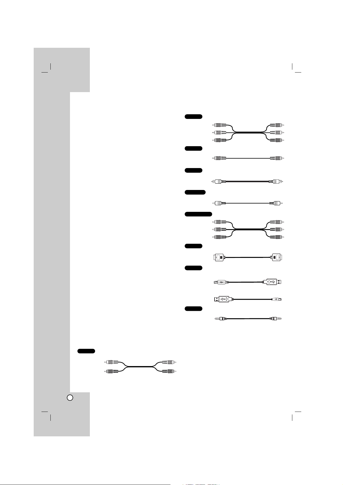
Required cables
The hookup diagrams on the subsequent pages
assume the use of the following connection cables.
You must purchase the connection cables separately
if necessary.
Analog audio cable
Analog audio/Composite video cable
Composite video cable
Optical digital audio cable
Coaxial digital audio cable
Component video cable
HDMI cable
USB cable
USB cable for PC connection
U
SB cable for MP3 Player (or Memory Card Reader, etc.)
LINE IN cable
Notes
•Turn off the power to all components before making
any connections.
• When connecting an audio/video cable, be sure to
match the color-coded pins to the appropriate jacks
on the components: yellow (video) to yellow; white
(left, audio) to white; and red (right, audio) to red.
• When connecting optical digital cables, insert the
cable plugs straight in until they click into place.
• Do not bend or tie optical digital cables.
LINE
USB
HDMI
COMPONENT
COAXIAL
Optical
VIDEO
A/V
AUDIO
Introduction
White (L)
Red (R)
White (L/audio)
Yellow (video)
Red (R/audio)
Yellow
Blue
Green
Red
5
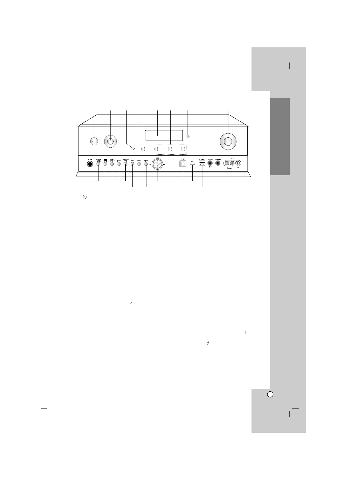
1. POWER ( )
Sets the unit to On and Standby.
2. INPUT SELECT
Select the input source.
Turn this knob until the input source you want
appears in the display window.
3. AUDYSSEY (2EQ) LED indicator
Lights up when Audyssey 2EQ is active.
4. DISPLAY
Displays various information about the currently
selected input source.
5. Display window
6. M1, M2, M3
Loads and stores various settings on this buttons
you set at one time.
7. Remote sensor
Receives control signals from the remote control.
8. MASTER VOLUME
Adjusts the volume of the unit to MIN (- 70.0dB)
through MAX (+10.0dB).
9. PHONES connector
Connect a stereo headphone plug ( 6.3 mm) to
PHONES connector for private listening.
10. SPEAKER LEVEL
Adjusts the level of each speaker.
11. TEST TONE
Checks the position and sound balance of
speakers in the following order.
(Front left speaker
→
Center speaker → Front right
speaker
→
Surround right speaker → Surround
center speaker
→
Surround left speaker
→
Subwoofer)
12. DIGITAL HDMI 1/2
Selects the input mode (ANALOG, COAXIAL,
OPTICAL 1/2/3).
Selects HDMI 1 or HDMI 2 on the HDMI mode.
13. FM/AM
Selects the unit’s tuner (FM and AM bands).
14. SURROUND MODE
Selects various surround effect.
15. DSP (Digital Signal Processor)
Selects DSP (Digital Signal Processor) mode.
16. BYPASS
Selects BYPASS mode.
17. SETUP
Accesses or removes the setup menu.
18. b/B/v/V (left/right/up/down)
Selects an item in the menu.
(ENTER)
Acknowledges the menu selection.
PRESET (-/+)
Selects preset number of radio.
TUN. (-/+)
Tunes in the desired radio station.
19. PC-LINK
Connect a USB port of PC.
20. USB port
Connect a USB port of USB device.
21. OPTICAL IN3
Connect a component with digital audio output
jacks.
22. AUTO Cal.
Sets the speaker setup automatically.
MIC IN
The included speaker setup microphone ( 3.5 mm)
is connected here for automatic speaker setup.
23. PORTABLE-IN (3.5 )
Connect a portable component.
24. AV IN (AUDIO L/R, VIDEO)
Connect the components with analog audio/video
output jacks (camcorder,game console, etc).
Introduction
Front Panel
/
l
INPUT
SELECT
DISPLAY
2EQ
M1 M2 M3
MASTER VOLUME
1 2 4 5 6 8
91011121314151617
18
19
20
21 23
2422
7
3
/
l
6
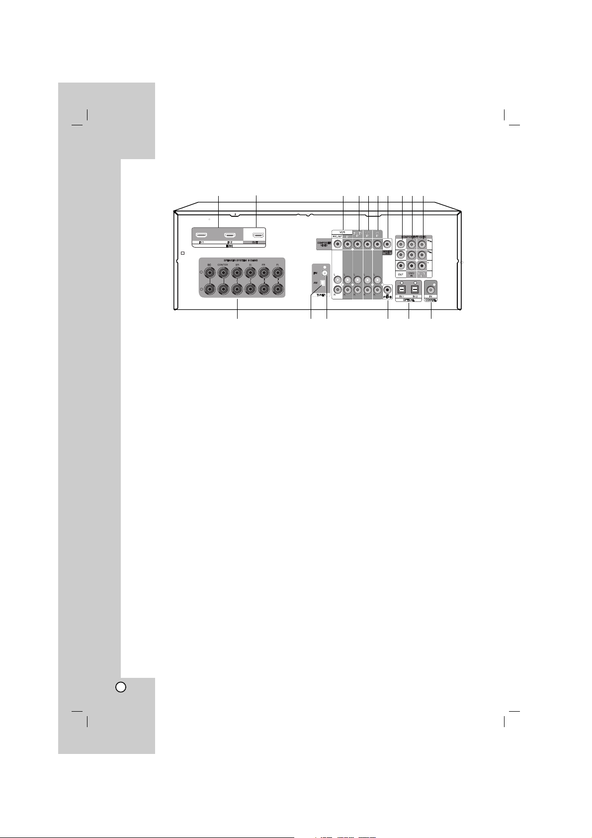
1. HDMI IN 1/2
Connect the component with HDMI output.
2. HDMI OUT
Connect a TV or component with HDMI input.
3. VCR IN/VCR REC. OUT
Connect a VCR.
4. TV/STB IN
Connect a TV, satellite tuner or set-top box.
5. DVD IN
Connect a DVD player to DVD IN jacks.
6. CD IN
Connect a CD player or Super Audio CD player to
CD IN jacks.
7. MONITOR OUT
Connect to a video input on your TV or projector.
8. COMPONENT VIDEO OUT
Connect a TV or projector to COMPONENT
VIDEO OUT jacks.
9. COMPONENT VIDEO DVD IN
Connect a DVD player with component video out
jacks to COMPONENT VIDEO DVD IN jacks.
10. COMPONENT VIDEO TV/STB IN
Connect a satellite tuner or set-top box, etc with
component video out jacks to COMPONENT
VIDEO TV/STB IN jacks.
11. SPEAKER SYSTEM
Connect the speakers.
12. AM ANTENNA
Connect an AM antenna.
13. FM ANTENNA
Connect a FM antenna.
14. SW (PRE OUT)
Connect the active subwoofer.
15. OPTICAL IN 1/2
Connect CD and DVD player, and other
components with an optical digital audio output.
16. COAXIAL
Connect CD and DVD player, and other
components with a coaxial digital audio output.
Rear Panel
+
-
1534
6
7
8
9
12
13 14 15 16
2
11
10
Notes
• The VCR IN video signal is not outputted to the VCR REC. OUT but outputted to the MONITOR OUT.
However, The VCR IN audio signal can be outputted to the VCR REC. OUT.
• Don’t connect a TV or MONITOR to HDMI 1/2 jacks. The unit may malfunction.
7
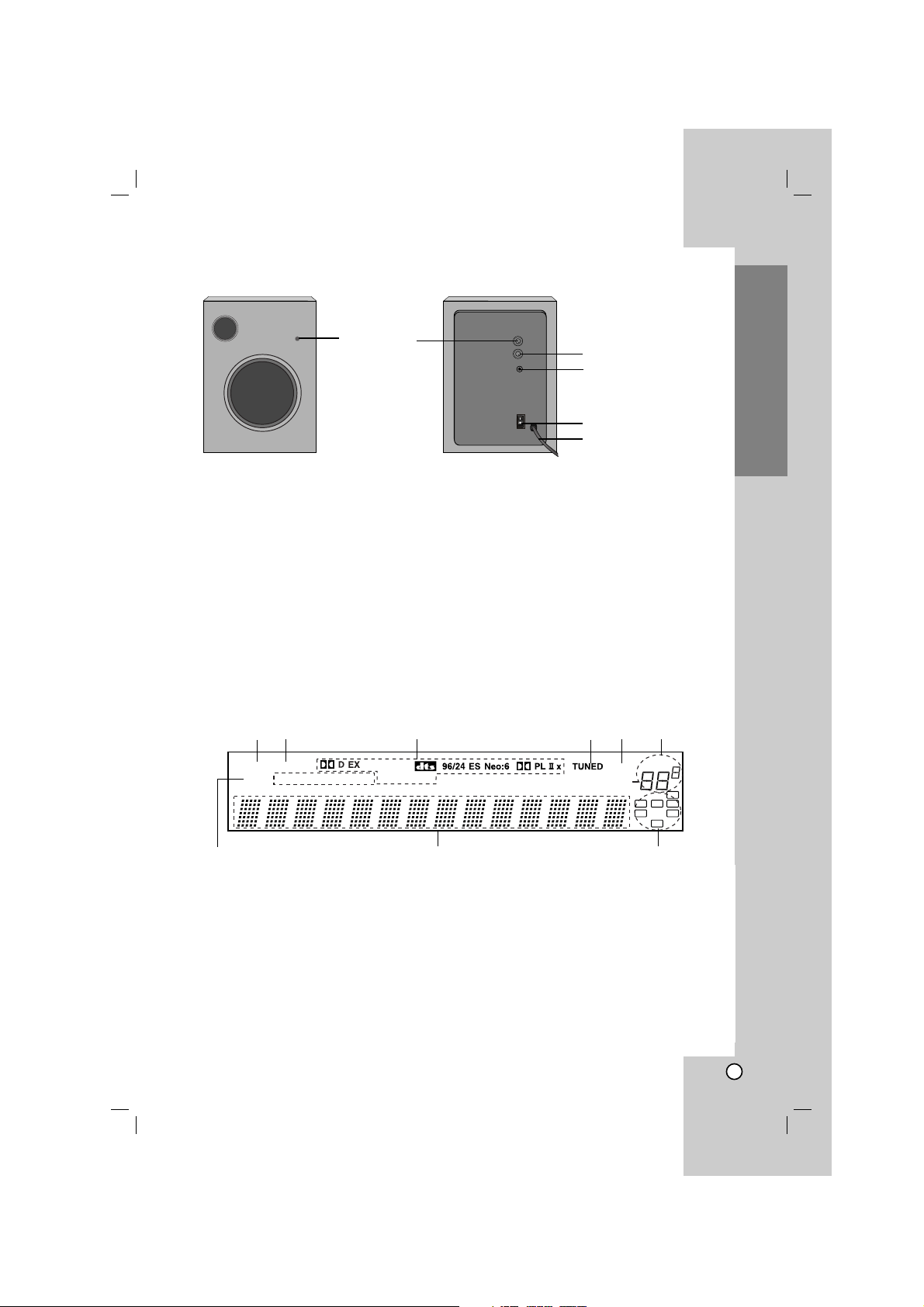
1. SLEEP indicator
Lights up when the Sleep function has been set.
2. HDMI indicator
Lights up when the HDMI function has been set.
3. Listening mode & format indicators
These indicators show the currently selected
listening mode and the format of digital input
signals.
4. TUNED indicator
Lights up when the unit is tuned into a radio station.
5. MUTE indicator
Flashes while the unit is muted.
6. VOLUME indicator
Displays the level of volume.
7. MIC indicator
Lights up when the unit is connect to MIC IN
connector.
8. Message area
Shows various information about the currently
selected source.
9. Speaker indicators
Displays the front, center, surround, surround center,
and subwoofer.
Introduction
Display window
SLEEP HDMI
MIC USB
MUTE
VOLUME
dB
SW
RCL
SR
SC
SL
ftms
WMA MP3
PCM Virtual FM ST. kHz MHz
1
5
3
4
26
7
8 9
Active Subwoofer
6
5
4
2
1
3
1. LED indicator
The RED lights when active subwoofer does not
receive a input for about 10 minutes. (Standby
mode.)
The BLUE lights when active subwoofer is
receiving a input.
2. Adjusting Volume (MIN - MAX)
Turn VOLUME dial clockwise/counterclockwise to
increase or decrease the sound level.
3. Frequency Controller (70Hz - 180Hz)
Turn HIGHCUT dial clockwise/counterclockwise to
adjust the frequency.
4. INPUT
Connect the unit’s SW(PRE OUT) to INPUT of
active subwoofer.
5. Power Switch
When pressing the upper part of this switch, the
Power is ON. Pressing the lower part turns OFF
the power.
6. Power Cord
Note
AR702NS model does not supply the active subwoofer.
8
Remote control operation range
Point the remote control at the remote sensor and
press the buttons.
• Distance: About 23 ft (7 m) from the front of the
remote sensor
• Angle: About 30° in each direction in front of the
remote sensor
Remote control battery installation
Remove the battery cover on the rear
of the remote control, and insert two
R06 (size AA) batteries with and
aligned correctly.
Notes
• Do not mix old and new batteries. Never mix
different types of batteries (standard, alkaline, etc.).
• If you intend not to use the remote control for a
long time, remove the batteries to prevent damage
from leakage or corrosion.
• Expired batteries should be removed as soon as
possible to prevent damage from leakage or
corrosion.
About the remote control modes
The remote control can be used to control up to ten
different components. The remote control has a
specific operating mode for use with each type of
component. Modes are selected by using the four
RECEIVER, DVD, VCR, and TV buttons on the
remote control.
1. Press RECEIVER, DVD, VCR, or TV buttons to
select a mode.
In RECEIVER Mode, you can control the unit.
In DVD Mode, you can control DVD player.
In VCR Mode, you can control VCR.
In TV Mode, you can control TV.
2. Use the buttons supported by that mode to
control the component.
Note
Some of the remote control operations may not work
as expected with other components.
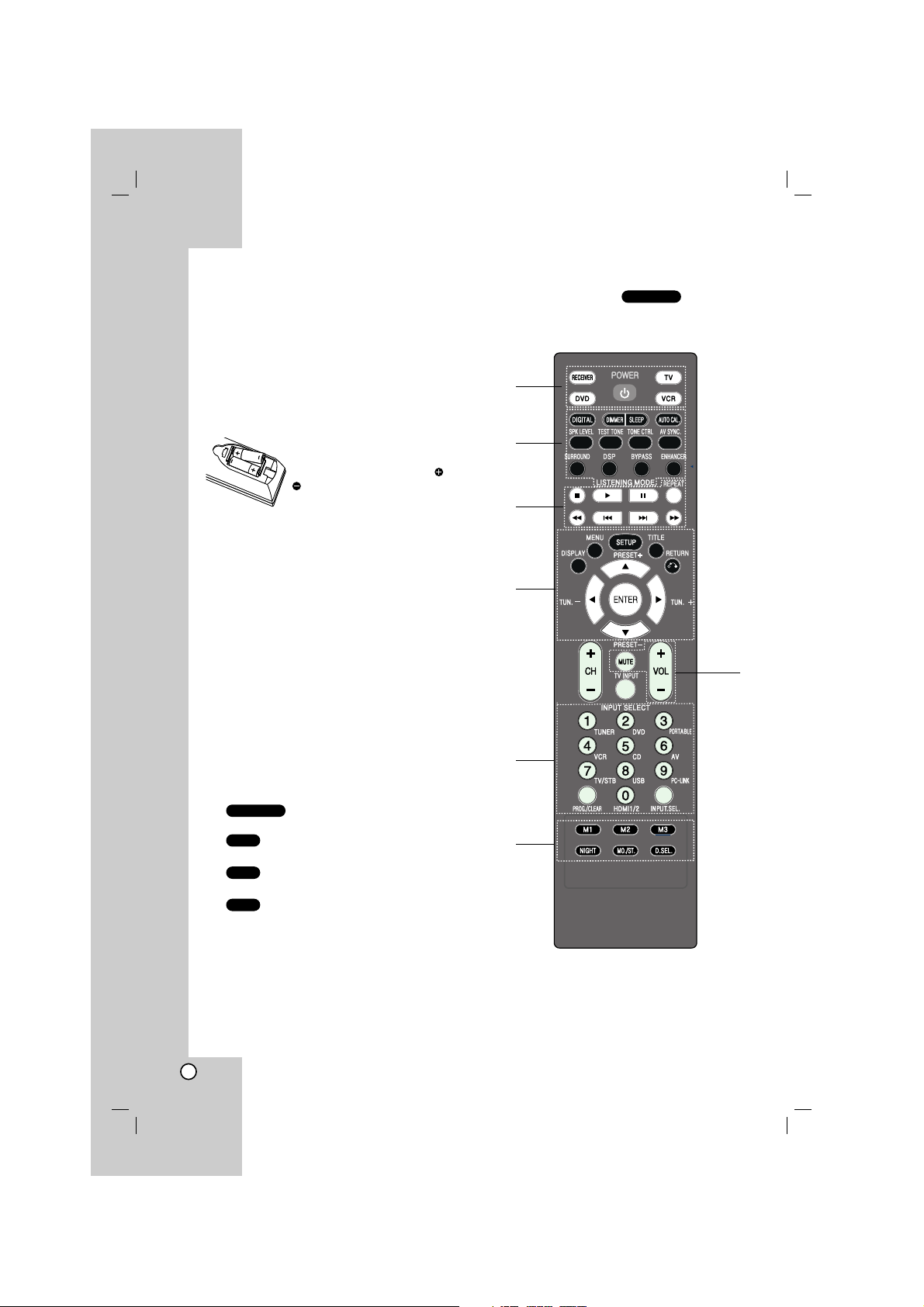
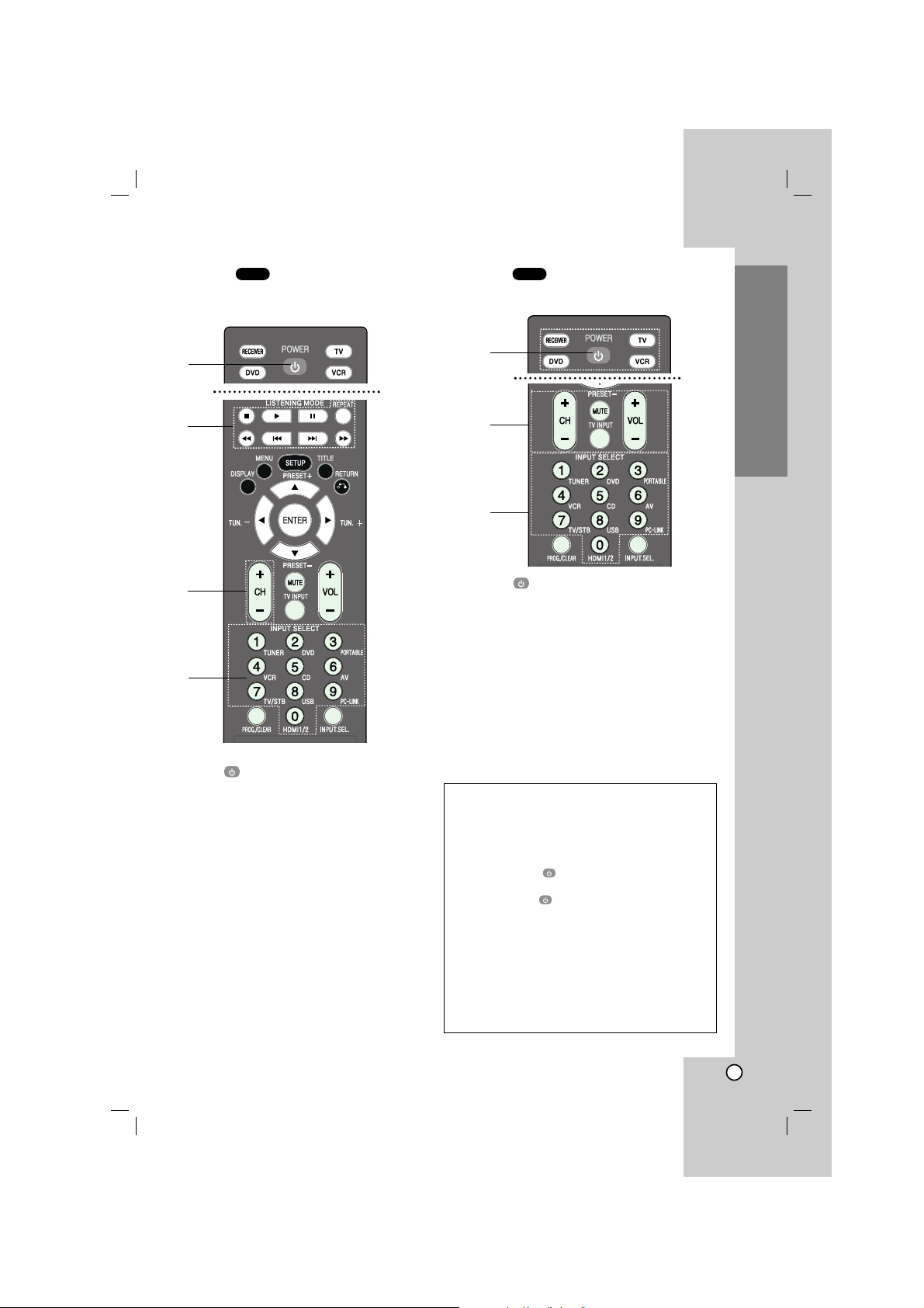
RECEIVER Mode
To set the remote control to RECEIVER mode,
press RECEIVER.
RECEIVER
TV
VCR
DVD
RECEIVER
Remote Control
1
2
4
7
5
6
3

9
1. POWER ( )
Switches the unit ON and OFF.
RECEIVER/DVD/TV/VCR
To operate the desired function with this remote
control, select the corresponding the buttons.
2. DIGITAL
Press this button to assign one of the digital inputs
to a source.
Selects HDMI 1 or HDMI 2 on the HDMI mode.
DIMMER
Press this button to adjust the brightness of the
display window.
SLEEP
Press this button to set the sleep timer.
AUTO CAL.
Starts Audyssey 2EQ automatic speaker setup;
and turns Audyssey 2EQ On and Off when setup
has been performed.
SPK LEVEL
Adjusts the speaker level from -10dB to +10dB.
TEST TONE
Checks the position and sound balance of
speakers in the following order.
TONE CTRL
Controls the BASS, MIDDLE, and TREBLE.
AV SYNC.
Adjusts the Audio Delay.
LISTENING MODE
- SURROUND
Selects various surround effect.
- DSP (Digital Signal Processor)
Selects DSP (Digital Signal Processor) mode.
- BYPASS
Selects BYPASS mode.
- ENHANCER
Enhances the sound quality of compressed input
signal.
3. USB mode only
- STOP (xx)
Stops playback.
- PLAY (B)
Starts playback.
- PAUSE(XX)
Pauses playback temporarily.
- REPEAT
Repeats track.
- SKIP (../>>)
Moves to the next or previous track.
4. DISPLAY
Accesses On-Screen display.
MENU
Access the menu on a disc.
SETUP
Accesses or removes setup menu.
TITLE
Displays the disc’s title menu, if available.
RETURN
Returns to the previous menu.
b/B/v/V (left/right/up/ down)
Selects an option in the menu.
ENTER
Acknowledges the menu selection.
PRESET (-/+)
Selects program of Radio.
TUN. (-/+)
Tunes in the desired radio station.
5. 0-9 numerical buttons
Selects numbered options in a menu.
INPUT SELECT buttons
- TUNER : Selects an FM or AM broadcast
- DVD : Selects a DVD mode.
- PORTABLE : Selects a POTABLE mode.
- VCR : Selects a VCR mode.
- CD : Selects a CD mode.
- AV : Selects an AV mode.
- TV/STB : Selects a TV/STB mode.
- USB : Selects an USB mode.
- PC-LINK : Selects a PC-LINK mode.
PROG./CLEAR
Stores a radio station’s frequency in the tuner’s
memory.
HDMI1/2
Switches the HDMI mode to HDMI 1 and HDMI 2.
INPUT.SEL.
Selects the input settings.
6. M1, M2, M3
Loads and stores various settings on this buttons
you set at one time.
NIGHT
Reduces the dynamic range of Dolby Digital
material so that you can still hear quiet parts even
when listening at low volume levels
MO./ST.
Selects the mono or stereo during receiving a FM
broadcast.
D.SEL
Selects a card on the USB mode in case that more
than one memory cards are connected to the USB
port.
7. MUTE
Mutes the sound.
VOLUME (-/+)
Adjusts the volume.
Introduction
10
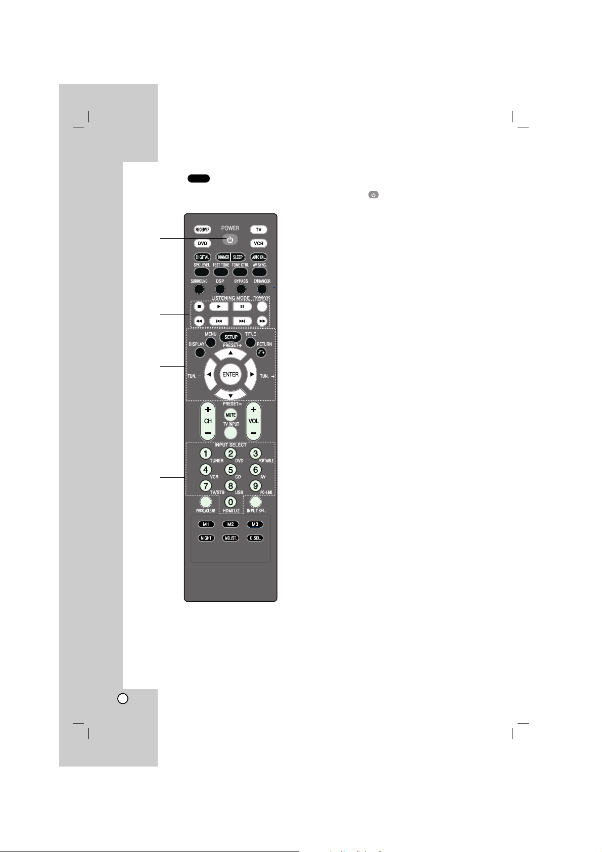
DVD Mode
To set the remote control to DVD mode, press
DVD.
1. POWER ( )
Switches the unit ON and OFF.
2. STOP (xx)
Stops playback.
PLAY (B)
Starts playback.
PAUSE(XX)/STEP
Pauses playback temporarily. Press this button
repeatedly to play Frame-by-Frame.
REPEAT
Repeats chapter, track, title or all.
SCAN(
bbbb/BBBB
)
Searches backward or forward.
SKIP (../>>)
Moves to the next or previous chapter or track.
3. DISPLAY
Accesses On-Screen display.
MENU
Access the menu on a disc.
SETUP
Accesses or removes setup menu.
TITLE
Displays the disc’s title menu, if available.
RETURN
Returns to the previous menu.
b/B/v/V (left/right/up/ down)
Selects an option in the menu.
ENTER
Acknowledges the menu selection.
4. 0-9 numerical buttons
Selects numbered options in a menu.
DVD
1
2
3
4
11
VCR Mode
To set the remote control to VCR mode, press
VCR.
1. POWER ( )
Switches the unit ON and OFF.
2. STOP (xx)
Stops playback.
PLAY (B)
Starts playback.
PAUSE(XX)/STEP
Pauses playback temporarily. Press this button
repeatedly to play Frame-by-Frame.
SCAN (
bbbb/BBBB
)
Searches backward or forward.
3. CH (-/+)
Selects the channel.
4. 0-9 numerical buttons
Selects numbered options in a menu.
TV Mode
To set the remote control to TV mode, press TV.
1. POWER ( )
Switches the unit ON and OFF.
2. CH (-/+)
Selects the channel.
MUTE
Mutes the sound.
TV INPUT
Selects the TV’s source.
VOLUME (-/+)
Adjusts the volume.
3. 0-9 numerical buttons
Selects numbered options in a menu.
TVVCR
Introduction
1
1
2
3
Controlling the TV
You can control the channel, sound level, input
source, and power switch of your LG TV with the
supplied Remote Control.
Setting Remote Control Codes for LG TV
1. Hold POWER ( ) and press CH (-/+) button
repeatedly until the TV on or off.
2. The POWER ( ), CH (-/+), VOLUME (-/+),
numerical buttons and TV INPUT buttons on
remote control can operate the LG TV.
Note
If the remote control does not operate your particular TV,
try the other code or use the remote control originally
supplied with the LG TV. (LG and Gold Star)
Due to the variety of codes used by manufacturers, OUR
COMPANY cannot guarantee that the remote control will
operate every LG TV model.
2
3
4
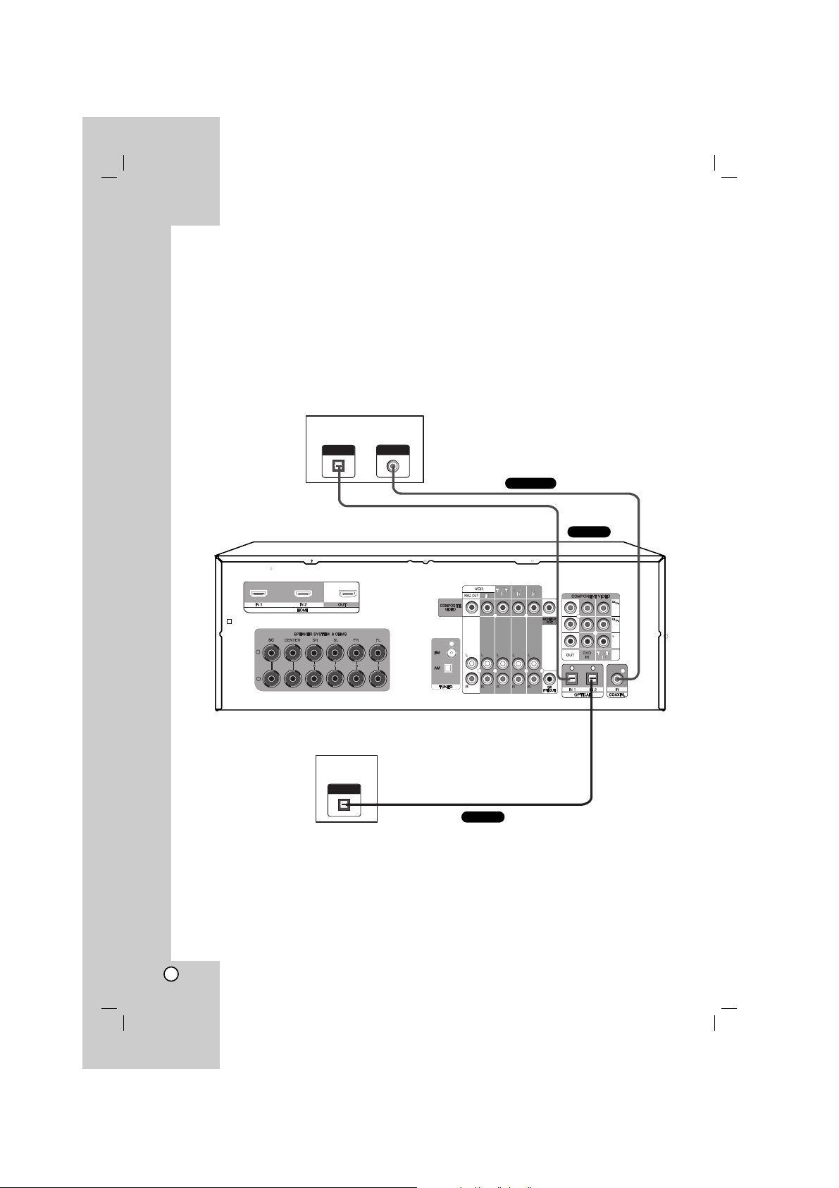
12
Connecting components with digital audio output jacks
Connecting a DVD player (or Digital device), TV monitor or satellite tuner (or
Set top box etc.)
1. Connect the audio jacks.
For details of the required cables, see the page 4.
Notes
•You can also connect the device to OPTICAL IN 3 jack on the front panel
• Connect to either the DVD COAXIAL IN or DVD OPTICAL IN 1 jack.
•You can listen to the sound of your TV by connecting your TV’s audio output jacks to the TV/STB AUDIO IN
jacks on the unit. In this case, do not connect the TV’s video output jack to the COMPOSITE VIDEO
(TV/STB) IN jack on the unit.
OPTICAL OUT
COAXIAL OUT
DVD player (or Digital device)
OPTICAL OUT
Satellite tuner
(or Set top box etc.)
+
-
Optical
Optical
COAXIAL
Installation
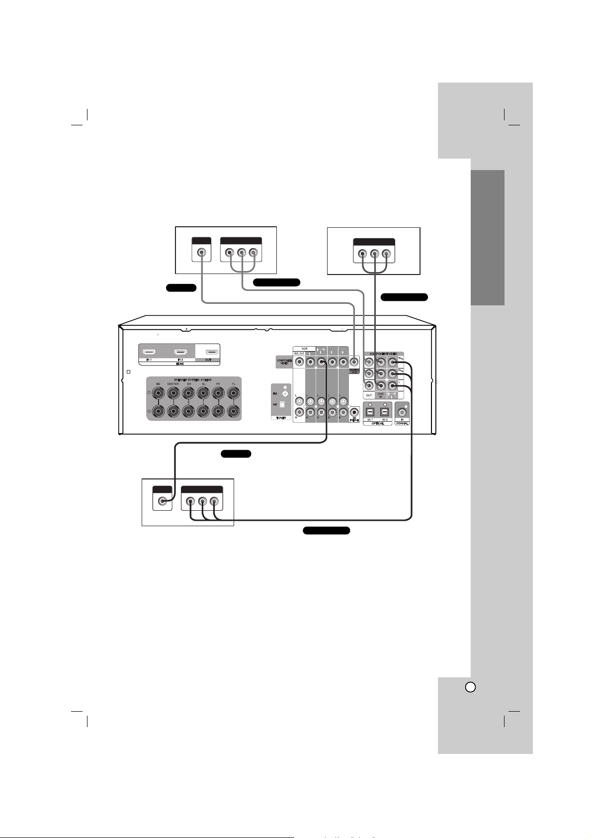
13
2. Connect the video jacks.
For details of the required cables, see the page 4.
The following illustration shows how to connect a TV or satellite tuner (Set top box, etc) and a DVD player
with COMPONENT VIDEO (Y, C
B/PB, CR/PR) output jacks.
3. Select the input source to play the component.
For details, see the page 25.
Note
Connect to either the COMPOSITE VIDEO OUT or COMPONENT VIDEO OUT jacks.
Installation
DVD player (or Digital device)
Satellite tuner (or Set top box, etc)
VIDEO OUT
COMPONENT VIDEO OUT
COMPONENT VIDEO OUT
VIDEO OUT
COMPONENT VIDEO OUT
TV monitor
VIDEO INPUT
COMPONENT VIDEO INPUT
+
-
COMPONENT
VIDEO
COMPONENT
VIDEO
COMPONENT
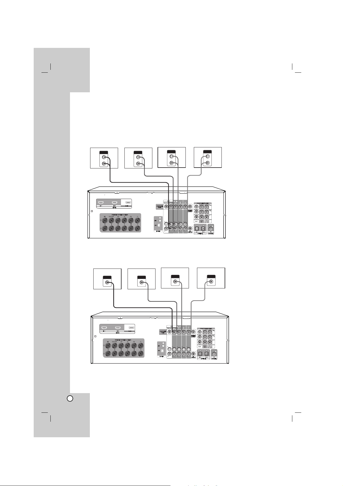
14
Connecting components with analog audio jacks
Connecting audio components
1. Connect the audio jacks with analog audio cable.
For details of the required cables, see the page 4.
2. Connect the video jacks with composite video cable.
For details of the required cables, see the page 4.
3. Select the input source to play the component.
For details, see the page 25.
AUDIO OUT
L
R
VCR
AUDIO OUT
L
R
DVD player
AUDIO OUT
L
R
CD player
AUDIO OUT
L
R
Satellite tuner (or
Set top box etc.)
+
-
VCR DVD player CD player
Satellite tuner (or
Set top box etc.)
VIDEO INPUT
VIDEO INPUT
VIDEO INPUT
VIDEO INPUT
+
-
 Loading...