

Page 1

Room Air Conditioner
SVC MANUAL(Exploded View)
MODEL : AMNW18GDCL0 [LMN186HVT]
CAUTION
Before Servicing the unit, read the safety precautions in General SVC manual.
Only for authorized service personnel.
Internal Use Only
http://www.lge.com
Page 2
- 2 -
Copyright ©2009 LG Electronics. Inc. All right reserved.
Only for training and service purposes
LGE Internal Use Only
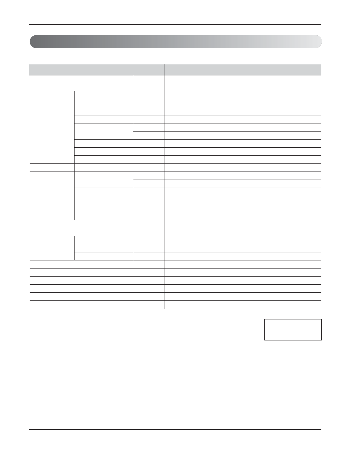
1. Specification
Indoor
Note:
1. Capacities are based on the following conditions:
Cooling: - Indoor Temperature 27°C(80.6°F) DB/19°C(66.2°F) WB
- Outdoor Temperature 35°C(95°F) DB/24°C(75.2°F) WB
Heating: - Indoor Temperature 20°C(68°F) DB/15°C(59°F) WB
- Outdoor Temperature 7°C(44.6°F) DB/6°C(42.8°F) WB
Piping Length - Interconnecting Piping Length 7.5m
- Level Difference of Zero
2. Wiring cable size must comply with the applicable local and national code.
3. The specification may be subject to change without prior notice for purpose of improvement.
Conversion Formula
kW = Btu/h x 0.0002931
cfm = CMM x 35.3
Power Supply Ø / V / Hz
Capacity(*) Btu/h Class
Current Running Current A
Fan Motor Type
Fan Type
Motor Output(W) x No. of Unit
Air Flow Rate CMM
(H / M / L) CFM
External Static Pressure mmAq
Capacitor μF / Vac
Drive
Coil Row x Column x FPI
Dimensions Body mm
(W x H x D) inch
Decorative Panel mm
inch
Net Weight Body kg (lbs)
Decorative Panel kg (lbs)
Air Filter
Sound Level (H / M / L) dB(A)+3
Piping Liquid mm (inch)
Connections Gas mm (inch)
Drain(OD/ID) mm (inch)
Dehumidification Rate l/h
Safety Devices
Temperature Sensor
Refrigerant
Refrigerant Control
Transmission Interunit Cable No. x AWG
Model
AMNW18GDCL0 [LMAN186HV]
1/208-230/60
18,000
0.28
BLDC
Cross Flow Fan
20x1
12/10/8.2
247/230/212
-
-
Direct Drive
3R x 18C x 22
1030 x 325 x 250
40-9/16 x 12-25/32 x 9-27/32
-
-
11(24.5)
-
Long Life Filter
37/33/28
6.35 (1/4)
12.7 (1/2)
21.5/16 (0.846/0.630)
1.9
Fuse, Thermal Protector for Fan Motor
Thermistor
R410A
EEV(in Outdoor unit or BD)
4×18(including earth)
Page 3

- 3 -
Copyright ©2009 LG Electronics. Inc. All right reserved.
Only for training and service purposes
LGE Internal Use Only
2. Piping Diagrams
Indoor
LOC. Description PCB Connector
Th1 Thermistor for sunction air temperature
CN-TH1(Indoor)
Th2 Thermistor for evaporator inlet temperature
Th3 Thermistor for evaporator outlet temperature CN-TH2(Indoor)
Th4 Thermistor for evaporator middle temperature CN-TH3(Indoor)
Th4
Th2
COOLING
HEATING
Heat exchang
CFF
er
Gas pipe connection port
(flare connection)
Th3
Th1
Liquid pipe connection port
(flare connection)
Page 4

- 4 -
Copyright ©2009 LG Electronics. Inc. All right reserved.
Only for training and service purposes
LGE Internal Use Only
3. Wiring Diagrams
Indoor Unit
CN-IN/N
CN-COM
RY-COMP(3)
CN-SUB
CN-U/D
CN-L/R
CN-OPTION
CN-DISP3
CN-12V
CN-HVB
CN-DISP1
CN-TH1
CN-TH2
CN-TH3
CN-SW
CN-DISPLAY
CN-12V
CN-SUB
CN-SUB1
CN-U/D1
CN-UD
CN-U/D2
CN-L/R
Page 5

- 5 -
Copyright ©2009 LG Electronics. Inc. All right reserved.
Only for training and service purposes
LGE Internal Use Only
4. Exploded View
Note) * Please ensure GCSC since the replacement parts may be changed depending upon the buyer's request.
Please check the correct parts in View RPL(Replacement Part List) on GCSC.
(GCSC Website http://www.lge.com)
135316
135313
152301
268711G
W6631A
152313
159830B
159830A
268711F
135511
131410
267110
W50400
146811B
147582
135311
149304
354212
352150
147581B
342800
354210
W51620A
359011
146811A
147581A
W51620B
352116
146811C
268711D
35211B
352115
135500B
249951
135500A
268711E
W6640
149303
733010
135500C
135090
263230C
346810
266090
268711C
263230B
263230A
Page 6

P/NO : MFL61777626
NOVEMBER, 2010
 Loading...