

Page 1
INSTALLATION MANUAL
AIR
CONDITIONER
ENGLISH
FRANÇAIS
Please read this installation manual completely before installing the product.
Installation work must be performed in accordance with the national wiring
standards by authorized personnel only.
Please retain this installation manual for future reference after reading it thoroughly.
Ceiling Cassette - 1Way (Art Type)
Original instruction
MFL67855413
Rev.00_031119
Copyright © 2013 - 2019 LG Electronics Inc. All Rights Reserved.
www.lg.com
Page 2

Table of contents
TABLE OF CONTENTS
3 INSTALLATION PARTS
4 SAFETY PRECAUTIONS
7 INSTALLATION
7 Selection of the Best Location
8 Ceiling Dimension and Hanging Bolt Location
9 Installation of Decoration Panel (Grille Type)
10 Drain Piping
11 Wiring Connection
13 Name and function of wired remote controller
14 DIP Switch Setting
2 Indoor Unit
Page 3
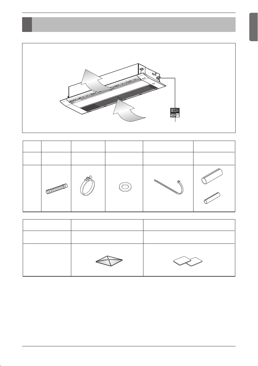
Installation Parts
Outlet
Installation Parts
ENGLISH
Grille type
Name
Quantity
Shape
Drain hose
Name
Quantity
Shape
1 EA
Inlet
Clamp metal
2 EA
Paper pattern for installation
Washer for
hanging bracket
8 EA
1 EA
Wired Remote Controller
Plastic band
4 EA
Installation and Owner's manual
Insulation for
for liquid pipe
1 EA
fitting
1 SET
for gas pipe
Installation Manual 3
Page 4
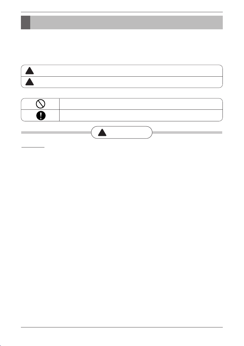
Safety Precautions
Safety Precautions
To prevent injury to the user or other people and property damage, the following instructions must be followed.
n Be sure to read before installing the air conditioner.
n Be sure to observe the cautions specified here as they include important items related to safety.
n Incorrect operation due to ignoring instruction will cause harm or damage. The seriousness is classified by the
following indications.
!
WARNING
!
CAUTION
n Meanings of symbols used in this manual are as shown below.
Installation
• Do not use a defective or underrated circuit breaker. Use this appliance on a dedicated circuit.
- There is risk of fire or electric shock.
• For electrical work, contact the dealer, seller, a qualified electrician, or an Authorized Service Center.
- Do not disassemble or repair the product. There is risk of fire or electric shock.
• Always ground the product.
- There is risk of fire or electric shock.
• Install the panel and the cover of control box securely.
- There is risk of fire or electric shock.
• Always install a dedicated circuit and breaker.
- Improper wiring or installation may cause fire or electric shock.
• Use the correctly rated breaker or fuse.
- There is risk of fire or electric shock.
• Do not modify or extend the power cable.
- There is risk of fire or electric shock.
• Do not install, remove, or reinstall the unit by yourself (customer).
- There is risk of fire, electric shock, explosion, or injury.
• Be cautious when unpacking and installing the product.
- Sharp edges could cause injury. Be especially careful of the case edges and the fins on the
condenser and evaporator.
• For installation, always contact the dealer or an Authorized Service Center.
- There is risk of fire, electric shock, explosion, or injury.
• Do not install the product on a defective installation stand.
- It may cause injury, accident, or damage to the product.
• Be sure the installation area does not deteriorate with age.
- If the base collapses, the air conditioner could fall with it, causing property damage, product failure,
and personal injury.
• Do not turn on the breaker or power under condition that front panel, cabinet, top cover, control box
cover are removed or opened.
This symbol indicates the possibility of death or serious injury.
This symbol indicates the possibility of injury or damage to properties only.
Be sure not to do.
Be sure to follow the instruction.
!
WARNING
4 Indoor Unit
Page 5

Safety Precautions
- Otherwise, it may cause fire, electric shock, explosion or death.
ENGLISH
• Use a vacuum pump or Inert (nitrogen) gas when doing leakage test or air purge. Do not compress air
or Oxygen and Do not use Flammable gases. Otherwise, it may cause fire or explosion.
- There is the risk of death, injury, fire or explosion.
Operation
• Do not let the air conditioner run for a long time when the humidity is very high and a door or a
window is left open.
- Moisture may condense and wet or damage furniture.
• Take care to ensure that power cable could not be pulled out or damaged during operation.
- There is risk of fire or electric shock.
• Do not place anything on the power cable.
- There is risk of fire or electric shock.
• Do not plug or unplug the power supply plug during operation.
- There is risk of fire or electric shock.
• Do not touch(operate) the product with wet hands.
- There is risk of fire or electrical shock.
• Do not place a heater or other appliances near the power cable.
- There is risk of fire and electric shock.
• Do not allow water to run into electric parts.
- It may cause There is risk of fire, failure of the product, or electric shock.
• Do not store or use flammable gas or combustibles near the product.
- There is risk of fire or failure of product.
• Do not use the product in a tightly closed space for a long time.
- Oxygen deficiency could occur.
• When flammable gas leaks, turn off the gas and open a window for ventilation before turn the product
on.
- Do not use the telephone or turn switches on or off. There is risk of explosion or fire.
• If strange sounds, or smell or smoke comes from product. Turn the breaker off or disconnect the
power supply cable.
- There is risk of electric shock or fire.
• Stop operation and close the window in storm or hurricane. If possible, remove the product from the
window before the hurricane arrives.
- There is risk of property damage, failure of product, or electric shock.
• Do not open the inlet grill of the product during operation. (Do not touch the electrostatic filter, if the
unit is so equipped.)
- There is risk of physical injury, electric shock, or product failure.
• When the product is soaked (flooded or submerged), contact an Authorized Service Center.
- There is risk of fire or electric shock.
• Be cautious that water could not enter the product.
- There is risk of fire, electric shock, or product damage.
• Ventilate the product from time to time when operating it together with a stove, etc.
- There is risk of fire or electric shock.
• Turn the main power off when cleaning or maintaining the product.
- There is risk of electric shock.
• When the product is not be used for a long time, disconnect the power supply plug or turn off the
breaker.
- There is risk of product damage or failure, or unintended operation.
• Take care to ensure that nobody could step on or fall onto the outdoor unit.
- This could result in personal injury and product damage.
Installation Manual 5
Page 6

Safety Precautions
!
CAUTION
Installation
• Always check for gas (refrigerant) leakage after installation or repair of product.
- Low refrigerant levels may cause failure of product.
• Install the drain hose to ensure that water is drained away properly.
- A bad connection may cause water leakage.
• Keep level even when installing the product.
- To avoid vibration or water leakage.
• Do not install the product where the noise or hot air from the outdoor unit could damage the
neighborhoods.
- It may cause a problem for your neighbors.
• Use two or more people to lift and transport the product.
- Avoid personal injury.
• Do not install the product where it will be exposed to sea wind (salt spray) directly.
- It may cause corrosion on the product. Corrosion, particularly on the condenser and evaporator fins,
could cause product malfunction or inefficient operation.
Operation
• Do not expose the skin directly to cool air for long periods of time. (Don't sit in the draft.)
- This could harm to your health.
• Do not use the product for special purposes, such as preserving foods, works of art, etc. It is a
consumer air conditioner, not a precision refrigeration system.
- There is risk of damage or loss of property.
• Do not block the inlet or outlet of air flow.
- It may cause product failure.
• Use a soft cloth to clean. Do not use harsh detergents, solvents, etc.
- There is risk of fire, electric shock, or damage to the plastic parts of the product.
• Do not touch the metal parts of the product when removing the air filter. They are very sharp!
- There is risk of personal injury.
• Do not step on or put anyting on the product. (outdoor units)
- There is risk of personal injury and failure of product.
• Always insert the filter securely. Clean the filter every two weeks or more often if necessary.
A dirty filter reduces the efficiency of the air conditioner and could cause product malfunction or damage.
-
• Do not insert hands or other objects through the air inlet or outlet while the product is operated.
- There are sharp and moving parts that could cause personal injury.
• Do not drink the water drained from the product.
- It is not sanitary and could cause serious health issues.
• Use a firm stool or ladder when cleaning or maintaining the product.
- Be careful and avoid personal injury.
• Replace the all batteries in the remote control with new ones of the same type. Do not mix old and
new batteries or different types of batteries.
- There is risk of fire or explosion.
• Do not recharge or disassemble the batteries. Do not dispose of batteries in a fire.
- They may burn or explode.
• If the liquid from the batteries gets onto your skin or clothes, wash it well with clean water. Do not use
the remote if the batteries have leaked.
- The chemicals in batteries could cause burns or other health hazards.
• If you eat the liquid from the batteries, brush your teeth and see doctor. Do not use the remote if the
batteries have leaked.
- The chemicals in batteries could cause burns or other health hazards.
• Means for disconnection must be incorporated in the fixed wiring in accordance with the wiring rules.
6 Indoor Unit
Page 7

Installation
NOTICE
Read completely, then follow step by step.
Selection of the Best Location
• There should not be any heat source or steam near the unit.
• There should not be any obstacles to the air circulation.
• A place where air circulation in the room will be good.
• A place where drainage can be easily obtained.
• A place where noise prevention is taken into consideration.
• Do not install the unit near the door way.
• Ensure the spaces indicated by arrows from the wall, ceiling, or other obstacles.
• The indoor unit must have the maintenance space.
Installation
ENGLISH
Ceiling
Ceiling board
500 or
more
1 000
or more
Above 2 500
3 300 or less
Ceiling board
200 or more
500 or
more
300 or less
Unit:mm
Floor
!
CAUTION
In case that the unit is installed near the sea, the installation parts may be corroded by
salt. The installation parts (and the unit) should be taken appropriate
anti-corrosion measures.
• Avoid the following installation location.
1. Such places as restaurants and kitchen where considerable amount of oil steam and flour is generated.
These may cause heat exchange efficiency reduction, or water drops, drain pump mal-function.
In these cases, take the following actions;
• Make sure that ventilation fan is enough to cover all noxious gases from this place.
• Ensure enough distance from the cooking room to install the air conditioner in such a place where it may
not suck oily steam.
2. Avoid installng air conditioner in such
places where cooking oil or iron powder is
generated.
3. Avoid places where inflammable gas is
generated.
4. Avoid place where noxious gas is
generated.
5. Avoid places near high frequency
generators.
Air conditioner
Take enough
distance
Cooking table
Use the ventilation fan
for smoke-collecting
hood with sufficient
capacity.
Installation Manual 7
Page 8

Installation
Set screw of
paper model (4 pieces)
Paper model
for installation
Ceiling board
70 mm
Adjust the same height
Ceiling board
Ceiling
Flat washer for M10
(accessory)
Keep the length of the bolt
from the bracket to 40 mm
Open the ceiling board
along the outer edge of the
paper model
Flat washer for M10
(accessory)
Hanging bolt
(W3/8 or M10)
Nut
(W3/8 or M10)
Nut
(W3/8 or M10)
Spring washer
(M10)
Air conditioner body
Keep the length of 20~22 mm
between the air conditioner bottom
surface and the ceiling surface
Ceiling Dimension and Hanging Bolt Location
• The dimensions of the paper model for installation are the same as those of the ceiling opening dimensions.
1 385
Ceiling
600
50
1 285
50
Level gauge
!
CAUTION
• This air-conditioner uses a drain pump.
• Install the unit horizontally using a level
gauge.
• During the installation, care should be
taken not to damage electric wires.
• Select and mark the position for fixing bolts and piping hole.
• Decide the position for fixing bolts slightly tilted to the drain
direction after considering the direction of drain hose.
• Drill the hole for anchor bolt on the wall.
450
306
400 4040
250
50
600
400 4040
306
250
1 180
TT Chassis
1 065
965
860
TU Chassis
450
354
50
354
(unit: mm)
Ceiling board
466
466
• The following parts are local purchasing.
• The following parts are local purchasing.
① Hanging bolt - W 3/8 or M10
① Hanging bolt - W 3/8 or M10
② Nut - W 3/8 or M10
② Nut - W 3/8 or M10
③ Spring washer - M10
③ Spring washer - M10
④ Plate washer - M10
④ Plate washer - M10
8 Indoor Unit
!
CAUTION
Tighten the nut and bolt to prevent unit
from falling off.
Page 9

Installation
Air conditioner unit
Decorative panel
Plasma filter
(applied only to plasma model)
Mesh
Control box cover
Decorative panel
fixing screws
(hexagon M6 screws)
(tightening about 20 mm)
Side cover
Air inlet grille
Air outlet vane
Installation of Decoration Panel (Grille Type)
The decoration panel has its installation
direction.
1. Open the air outlet vane, and extract side covers.
2. Remove the air inlet grille from the decoration panel.
3.
Hook decoration panel to indoor unit, using hooks attached at the backside of both side of decoration panel.
4. Arrange wires not to get caught between decoration panel and indoor unit.
5. Screw 7 fixing screws. (9, 12 kBtu/h : 6 screws)
6. Connect the vane motor connector and display connector. (Plasma connector for plasma model)
7. Install the air inlet grille (including the air filter) and side covers.
Before installing the decoration panel,
always remove the paper template.
ENGLISH
!
CAUTION
Install certainly the
decoration panel.
Cool air leakage causes
sweating.
Waterdrops fall.
Good example Bad example
Air conditioner
Decorative panel
Fit the insulator (this part) and
be careful for cool air leakage
unit
Ceiling
board
Cool air leakage
(no good)
Air conditioner
unit
Decorative panel
Installation Manual 9
Ceiling
board
Page 10

Installation
Maintenance
drain port
Upward
routing
not allowed
Pipe clamp
Indoor unit
1/50~1/100
Max 700 mm
Feed water
Drain pump
Drain pan
Flexible drain hose
(accessory)
Main
drain pipe
Glue the joint
Drain
port
Drain hose connection
Use the clip (accessory)
1/50~1/100 slope
Hanger
distance
Hanger bracket
Max 700 mm
Flexible drain hose
Insulation
Metal
clamp
Max
300 mm
1~15 m
Drain Piping
• Drain piping must have down-slope (1/50 to 1/100): be sure not to
provide up-and-down slope to prevent reversal flow.
• During drain piping connection, be careful not to exert extra force
on the drain port on the indoor unit.
• The outside diameter of the drain connection on the indoor unit is
32 mm.
Piping material: Polyvinyl chloride pipe VP-25 and pipe
fittings
•
Be sure to install heat insulation on the drain piping.
Heat insulation material: Polyethylene foam with
thickness more than 8 mm.
Drain Test
The air conditioner uses a drain pump to drain water.
Use the following procedure to test the drain pump operation:
• Connect the main drain pipe to the exterior
• Feed water to the flexible drain hose and
• Be sure to check the drain pump for normal
• When the test is complete, connect the
!
CAUTION
and leave it provisionally until the test
comes to an end.
check the piping for leakage.
operating and noise when electrical wiring
is complete.
flexible drain hose to the drain port on the
indoor unit.
The supplied flexible drain hose should
not be curved, neither screwed. The
curved or screwed hose may cause a
leakage of water.
10 Indoor Unit
Page 11

Installation
Wiring Connection
- Open the control box cover and connect the Remote controller cord and Indoor power wires.
- Remove the control box cover for electrical connection between the indoor and outdoor unit.
- Use the cord clamper to fix the cord.
!
CAUTION
The connecting cable connected to the indoor and outdoor unit should be complied
with the following specifications (This equipment shall be provided with a cord set
complying with the national regulation).
10±3 mm
35±5 mm
GN/YL
ENGLISH
NORMAL
CROSS-SECTIONAL
AREA 0.75 mm
20 mm
2
If the supply cord is damaged, it must be replaced by a special cord or assembly
available from the manufacturer of its service agent.
!
CAUTION
The Power cord connected to the unit should be selected according to the following
specifications.
Installation Manual 11
Page 12

Installation
Power wire
Round pressure terminal
Connect same thickness
wiring to both sides.
It is forbidden to
connect two to one
side.
It is forbidden to
connect wiring of
different thicknesses.
Precautions when laying power wiring
Use round pressure terminals for connections to the power terminal block.
When none are available, follow the instructions below.
- Do not connect wiring of different thicknesses to the power terminal block. (Slack in the power wiring may cause
abnormal heat.)
- When connecting wiring which is the same thickness, do as shown in the figure below.
- For wiring, use the designated power wire and connect firmly, then secure to prevent outside pressure being
exerted on the terminal block.
- Use an appropriate screwdriver for tightening the terinal screws. A screwdriver with a small head will strip the
head and make proper tighterning impossible.
- Over-tightening the terminal screws may break them.
12 Indoor Unit
Page 13

Name and function of wired remote controller
Operation Display Windows
Sub function Button
Airflow Button
Function Setting Button
Ventilation Button
Reservation Button
Up/Down/Left/Right Button
Room temperature Button
ESC Button
Operation Display Windows : Displays the status of operation and settings
Ventilation Button : For interlocking operations of air-conditioner and ventilator
Function Setting Button : To select the additional operations function
Airflow Button : To select the airflows
Sub function Button : To select the additional operations function
Reservation Button : To program the schedule
Up/Down/Left/Right Button : To change the settings in the menu
Room temperature Button : To check the indoor temperature
ESC Button : To exit from the menu
Set/Cancel Button : To save the settings in the menu
Temperature Control Button : To change the desired temperature
Fan Speed Button : To select the fan speed
On/Off Button : To turn on/off with a remote controller
Mode Selection Button : To select the operating mode
Wireless Remote Controller Receiver
Installation
ENGLISH
Set/Cancel Button
Temperature Control Button
On/Off Button
Operation Mode Selection Button
Wireless Remote Controller Receiver
Fan Speed Button
※ Some functions may not be operated and displayed depending on the product type.
※ It will display strange value to the room temperature if wired remote controller is not connected.
Installation Manual 13
Page 14

Installation
DIP Switch Setting
Function Description Setting Off Setting On Default
Communication
SW1
Cycle
SW2
Group Control
SW3
N/A (Default)
N/A (Default)
Selection of Master or Slave
-
-
Master
-
-
Slave
Off
Off
Off
Dry Contact Mode
SW4
Installation
SW5
Heater linkage
SW6
Ventilator linkage
SW7
Vane selection
(Console)
Region selection
Etc.
SW8
Selection of Dry Contact
Mode
Fan continuous operation
N/A
Selection of Ventilator
linkage
Selection of up/down
side Vane
Selection tropical region
Spare
Wired/Wireless remote
controller
Selection of Manual or Auto
operation Mode
Continuous operation
Removal
-
Linkage Removal
Up side + Down side Vane
General model
-
Auto
-
-
Working
Up side Vane
Only
Tropical model
-
Off
Off
Off
Off
Off
14 Indoor Unit
Page 15

MANUEL D'INSTALLATION
CLIMATISEUR
FRANÇAIS
Veuillez lire ce manuel dans son intégralité avant d'installer le climatiseur.
L'installation doit être effectuée conformément aux normes électriques nationales
par un personnel agréé uniquement.
Après avoir lu ce manuel attentivement, conservez-le pour pouvoir vous y reporter
ultérieurement.
Cassette 1 Voies(Plafond) (Art Type)
Traduction de l’instruction originale
www.lg.com
Copyright © 2013 - 2019 LG Electronics Inc. Tous droits réservés.
Page 16

Table des matières
TABLE DES MATIÈRES
3 ELEMENTS D'INSTALLATION
4 PRECAUTIONS DE SECURITE
7 INSTALLATION
7 Choix du meilleur emplacement.
8 Dimension du plafond et emplacement des boulons de support
9 Installation du Panneau décoratif (Type de grille)
10 Tuyauterie de drainage de l’unité intérieure
11 Câblage
13 Nom et fonction de la télécommande filaire (Accessoire)
14 Réglages du commutateur DIP
2 Unité intérieure
 Loading...