

LG ABUW18GM1S1 Installation Manual
<![endif]>FRANÇAIS ENGLISH
INSTALLATION MANUAL
AIR
CONDITIONER
Please read this installation manual completely before installing the product. Installation work must be performed in accordance with the national wiring standards by authorized personnel only.
Please retain this installation manual for future reference after reading it thoroughly.
www.lg.com
P/NO : MFL68500203

<![endif]>ENGLISH
2 TIPS FOR SAVING ENERGY
TIPS FOR SAVING ENERGY
Here are some tips that will help you minimize the power consumption when you use the air conditioner. You can use your air conditioner more efficiently by referring to the instructions below:
•Do not cool excessively indoors. This may be harmful to your health and may consume more electricity.
•Block sunlight with blinds or curtains while you are operating the air conditioner.
•Keep doors or windows closed tightly while you are operating the air conditioner.
•Adjust the direction of the air flow vertically or horizontally to circulate indoor air.
•Speed up the fan to cool or warm indoor air quickly, in a short period of time.
•Open windows regularly for ventilation as the indoor air quality may deteriorate if the air conditioner is used for many hours.
•Clean the air filter once every 2 weeks. Dust and impurities collected in the air filter may block the air flow or weaken the cooling / dehumidifying functions.
For your records
Staple your receipt to this page in case you need it to prove the date of purchase or for warranty purposes. Write the model number and the serial number here:
Model number :
Serial number :
You can find them labeled on the side of each unit.
Dealer’s name :
Date of purchase :
IMPORTANT SAFETY INSTRUCTIONS 3
IMPORTANT SAFETY INSTRUCTIONS
READ ALL INSTRUCTIONS BEFORE USING THE APPLIANCE.
Always comply with the following precautions to avoid dangerous situations and ensure peak performance of your product
! WARNING
It can result in serious injury or death when the directions are ignored
! CAUTION
It can result in minor injury or product damage when the directions are ignored
! WARNING
•Installation or repairs made by unqualified persons can result in hazards to you and others.
•Installation work must be performed in accordance with the National Electric Code by qualified and authorized personnel only.
•The information contained in the manual is intended for use by a qualified service technician familiar with safety procedures and equipped with the proper tools and test instruments.
•Failure to carefully read and follow all instructions in this manual can result in equipment malfunction, property damage, personal injury and/or death.
Installation
•Always perform grounding. Otherwise, it may cause electrical shock.
•Don’t use a damaged power cable. Otherwise, it may cause a fire or electrical shock.
•For installation of the product, always contact the service center or a professional installation agency. Otherwise, it may cause a fire, electrical shock, explosion or injury.
•Securely attach the electrical part cover to the indoor unit and the service panel to the outdoor unit. If the electrical part cover of the indoor unit and the service panel of the outdoor unit are not attached securely, it could result in a fire or electric shock due to dust, water, etc.
•Always install an earth leakage circuit breaker and a dedicated switching board. No installation may cause a fire and electrical shock.
•Do not keep or use flammable gases or combustibles near the air conditioner. Otherwise, it may cause a fire or the failure of product.
•Ensure that an installation frame of the outdoor unit is not damaged due to use for a long time. It may cause injury or an accident.
•Do not disassemble or repair the product randomly. It will cause a fire or electrical shock.
•Use a vacuum pump or Inert (nitrogen) gas when doing leakage test or air purge. Do not compress air or Oxygen and do not use Flammable gases. Otherwise, it may cause fire or explosion. There is the risk of death, injury, fire or explosion.
•Do not install the product at a place that there is concern of falling down. Otherwise, it may result in personal injury.
•Use caution when unpacking and installing. Sharp edges may cause injury.
•Do not turn on the breaker or power under condition that front panel, cabinet, top cover, control box cover are removed or opened. Otherwise, it may cause fire, electric shock, explosion or death.
<![endif]>ENGLISH

<![endif]>ENGLISH
4 IMPORTANT SAFETY INSTRUCTIONS
Operation
•Do not share the outlet with other appliances. It will cause an electric shock or a fire due to heat generation.
•Do not use the damaged power cable. Otherwise, it may cause a fire or electrical shock.
•Do not modify or extend the power cable randomly. Otherwise, it may cause a fire or electrical shock.
•Take care so that the power cable may not be pulled during operation. Otherwise, it may cause a fire or electrical shock.
•Turn off the unit if strange sounds, smell, or smoke comes from it. Otherwise, it may cause electrical shock or a fire.
•Keep the flames away. Otherwise, it may cause a fire.
•Do not use the power cable near the heating tools. Otherwise, it may cause a fire and electrical shock.
•Do not open the suction inlet of the indoor/outdoor unit during operation. Otherwise, it may electrical shock and failure.
•Do not allow water to run into electrical parts. Otherwise, it may cause the failure of machine or electrical shock.
•Do not touch the power cable with wet hands. It may cause electric shock and damage.
•Never touch the metal parts of the unit when removing the filter. They are sharp and may cause injury.
•Do not step on the indoor/outdoor unit and do not put anything on it. It may cause an injury through dropping of the unit or falling down.
•Do not place a heavy object on the power cable. Otherwise, it may cause a fire or electrical shock.
•When the product is submerged into water, always contact the service center. Otherwise, it may cause a fire or electrical shock.
•Take care so that children may not step on the outdoor unit. Otherwise, children may be seriously injured due to falling down.

IMPORTANT SAFETY INSTRUCTIONS 5
! CAUTION
Installation
•Install the drain hose to ensure that drain can be securely done. Otherwise, it may cause water leakage.
•Install the product so that the noise or hot wind from the outdoor unit may not cause any damage to the neighbors. Otherwise, it may cause dispute with the neighbors.
•Always inspect gas leakage after the installation and repair of product. Otherwise, it may cause the failure of product.
•Keep level parallel in installing the product. Otherwise, it may cause vibration or water leakage.
Operation
•Avoid excessive cooling and perform ventilation sometimes. Otherwise, it may do harm to your health.
•Use a soft cloth to clean. Do not use wax, thinner, or a strong detergent. The appearance of the air conditioner may deteriorate, change color, or develop surface flaws.
•Do not use an appliance for special purposes such as preserving animals vegetables, precision machine, or art articles. Otherwise, it may damage your properties.
•Do not place obstacles around the flow inlet or outlet. Otherwise, it may cause the failure of appliance or an accident.
<![endif]>ENGLISH

<![endif]>ENGLISH
6 TABLE OF CONTENTS
TABLE OF CONTENTS
2 |
TIPS FOR SAVING ENER- 15 |
LEAKAGE TEST AND |
|||
|
GY |
|
|
EVACUATION |
|
|
|
|
|
|
|
3 |
IMPORTANT SAFETY |
15 |
Preparation |
||
15 |
Leakage test |
||||
|
INSTRUCTIONS |
||||
|
16 |
Evacuation |
|||
|
|
||||
7 |
INSTALLATION OF OUT- |
||||
17 |
TEST RUNNING |
||||
|
DOOR UNIT |
||||
|
|
|
|
||
|
19 |
INSTALLATION GUIDE AT |
|||
|
|
||||
8 |
WIRING CONNECTION |
||||
|
|
THE SEASIDE |
|||
|
|
|
|
||
|
|
|
|
||
8Electrical Wiring
9Connecting Cables between Indoor Unit and Outdoor Unit
11 Connecting the cable to Outdoor Unit
20CONVENIENT FUNCTIONS
20 Pressure compensation function
12 CONNECTING PIPES
12Preparation of Piping
13Connecting the pipes to the Outdoor unit
14Forming the Piping
INSTALLATION OF OUTDOOR UNIT |
7 |
|
INSTALLATION OF OUTDOOR UNIT
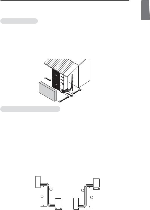
Installation Places
-If an awning is built over the unit to prevent direct sunlight or rain exposure, make sure that heat radiation from the condenser is not restricted.
-Ensure that the spaces indicated by arrows around front, back and side of the unit.
-Do not place animals and plants in the
- Take the air conditioner weight into |
where noise and vibration are |
minimum. |
|
- Select a place so that the warm
More than 300 mm
Fence obstaclesor
do not disturb neighbors.
Unit : mm
Sunroof


 More than


 300mm
300mm
More than 600 mm
More than 700 mm
Piping length and the elevation
Free Joint Single Outdoor
MODEL |
Pipe Size |
Length A (m) |
Elevation B (m) |
Additional |
||||
Gas |
Liquid |
Standard |
Max. |
Standard |
Max. |
Refrigerant (g/m) |
||
|
||||||||
|
|
|
|
|
|
|
|
|
ATUW18GPLS1 |
Ø12.7(1/2) |
Ø6.35(1/4) |
7.5 |
25 |
5 |
15 |
20 |
|
ABUW18GM1S1 |
Ø12.7(1/2) |
Ø6.35(1/4) |
7.5 |
25 |
5 |
15 |
20 |
|
|
|
|
|
|
|
|
|
|
ATUW48LMLS1 |
Ø19.05(3/4) |
Ø9.52(3/8) |
7.5 |
50 |
5 |
30 |
40 |
|
ATUW54LMLS1 |
Ø19.05(3/4) |
Ø9.52(3/8) |
7.5 |
50 |
5 |
30 |
40 |
|
|
|
|
|
|
|
|
|
|
ABUW48LM3S1 |
Ø19.05(3/4) |
Ø9.52(3/8) |
7.5 |
50 |
5 |
30 |
40 |
|
ABUW54LM3S1 |
Ø19.05(3/4) |
Ø9.52(3/8) |
7.5 |
50 |
5 |
30 |
40 |
|
|
|
|
|
|
|
|
|
|
APUW48LT3S1 |
Ø19.05(3/4) |
Ø9.52(3/8) |
7.5 |
50 |
5 |
30 |
40 |
|
If installed tube is shorter than Standard length, additional charging is not necessary. Additional Refrigerant = (Max. Length - Standard Length) x Additional refrigerant (g)
Indoor unit
Outdoor unit
|
A |
|
A |
|
|
|
|
B |
Outdoor unit |
Indoor unit |
B |
|
|
|
<![endif]>ENGLISH

<![endif]>ENGLISH
8 WIRING CONNECTION
WIRING CONNECTION
Electrical Wiring
Perform the electrical wiring work according to the electrical wiring connection.
-All wiring must comply with local requirements.
-Select a power source that is capable of supplying the current required by the air conditioner.
-Use a recognized ELCB(Electric Leakage Circuit Breaker) between the power source and the unit. A disconnection device to adequately disconnect all supply lines must be fitted.
-Model of circuit breaker recommended by authorized personnel only

 ELCB
ELCB
Main
power source

 Switch box
Outdoor
Indoor
Model |
Phase(Ø) |
ELCB |
|
|
|
ATUW18GPLS1 |
1 |
15A |
|
|
|
ABUW18GM1S1 |
1 |
15A |
|
|
|
ATUW48LMLS1 |
3 |
20A |
|
|
|
ATUW54LMLS1 |
3 |
20A |
|
|
|
ABUW48LM3S1 |
3 |
20A |
|
|
|
ABUW54LM3S1 |
3 |
20A |
|
|
|
APUW48LT3S1 |
3 |
20A |
|
|
|
WIRING CONNECTION 9
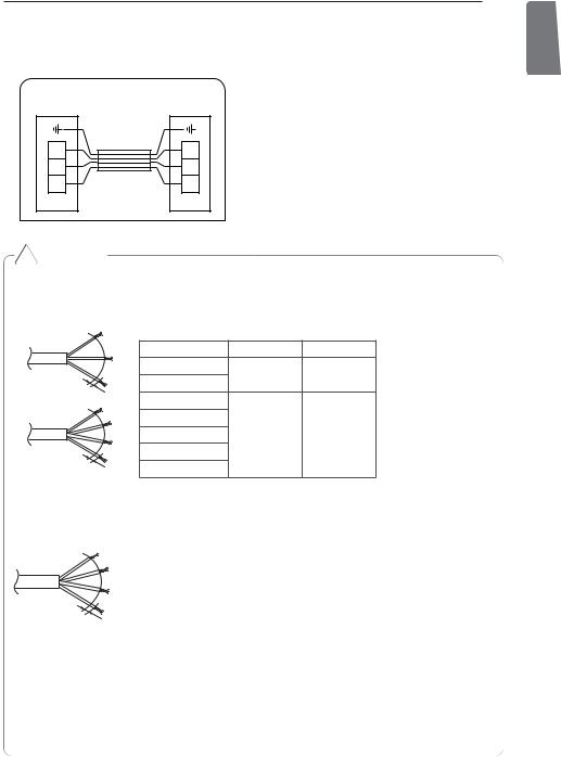
Connecting Cables between Indoor Unit and Outdoor Unit
Outdoor |
Indoor |
unit |
unit |
3 |
3 |
2 |
2 |
1 |
1 |
! CAUTION
The power cable connected to the outdoor unit should be complied with IEC 60245 or HD 22.4 S4 (This equipment shall be provided with a cable set complying with the national regulation.
1 Phase(Ø) |
|
NORMAL CROSS-SECTIONAL AREA |
||
|
|
|
|
|
|
|
Model |
Phase(Ø) |
Area(Ø) |
GN/YL |
|
ATUW18GPLS1 |
1 |
2.5 |
|
ABUW18GM1S1 |
|||
|
|
|||
20mm |
|
|
||
ATUW48LMLS1 |
|
|
||
|
|
|
|
|
3 Phase(Ø) |
|
ATUW54LMLS1 |
|
|
|
|
|
|
|
GN/YL |
|
ABUW48LM3S1 |
3 |
2.5 |
|
ABUW54LM3S1 |
|
|
|
|
|
|
|
|
2 |
|
APUW48LT3S1 |
|
|
0 |
|
|
||
|
mm |
|
|
|
The connecting cable connected to the outdoor unit should be complied with IEC 60245 or HD 22.4 S4 (This equipment shall be provided with a cable set complying with the national regulation.)
GN/YL
20mm
NORMAL CROSS-SECTIONAL AREA
Model |
Phase(Ø) |
Area(mm²) |
|
|
|
|
|
ATUW18GPLS1 |
1 |
0.75 |
|
|
|||
ABUW18GM1S1 |
|||
|
|
||
|
|
|
|
ATUW48LMLS1 |
|
|
|
|
|
|
|
ATUW54LMLS1 |
|
|
|
|
|
|
|
ABUW48LM3S1 |
3 |
1.00 |
|
|
|
|
|
ABUW54LM3S1 |
|
|
|
|
|
|
|
APUW48LT3S1 |
|
|
|
|
|
|
When the connection line between the indoor unit and outdooor unit is over 40 m, connect the telecommunication line and power line separately.
<![endif]>ENGLISH
If the supply cable is damaged, it must be replaced by a special cable or assembly availible from the manufacturer of its service agent.

<![endif]>ENGLISH
10 WIRING CONNECTION
Precautions when laying power wiring
Use round pressure terminals for connections to the power terminal block.
Power wire
When none are available, follow the instructions below.
-Do not connect wiring of different thicknesses to the power terminal block. (Slack in the power wiring may cause abnormal heat.)
-When connecting wiring which is the same thickness, do as shown in the figure below.
Connect same thickness |
It is forbidden to connect |
It is forbidden to |
|||||||||||||||||
wiring to both sides. |
two to one side. |
connect wiring of |
|||||||||||||||||
|
|
|
|
|
|
|
|
|
|
|
|
|
|
different thicknesses. |
|||||
|
|
|
|
|
|
|
|
|
|
|
|
|
|
|
|
|
|
|
|
|
|
|
|
|
|
|
|
|
|
|
|
|
|
|
|
|
|
|
|
|
|
|
|
|
|
|
|
|
|
|
|
|
|
|
|
|
|
|
|
|
|
|
|
|
|
|
|
|
|
|
|
|
|
|
|
|
|
|
|
|
|
|
|
|
|
|
|
|
|
|
|
|
|
|
|
|
|
|
|
-For wiring, use the designated power wire and connect firmly, then secure to prevent outside pressure being exerted on the terminal block.
-Use an appropriate screwdriver for tightening the terinal screws. A screwdriver with a small head will strip the head and make proper tighterning impossible.
-Over-tightening the terminal screws may break them.
WIRING CONNECTION 11
Connecting the cable to Outdoor Unit
Remove the side panel for wiring connection.
Use the cord clamp to fix the cable.
Earthing work
-Connect the cable of diameter more to the earthing terminal provided in the control box and do earthing.
<![endif]>ENGLISH
Tubing Cover
Power cord
Power connecting cable
Connecting cable terminal


 Power cord terminal
Cord clamp
* Make sure the rubber bushes are properly used in knock-out holes after connecting main power.
!CAUTION
•The circuit diagram is not subject to change without notice.
•Be sure to connect wires according to the wiring diagram.
•Connect the wires firmly, so that not to be pulled out easily.
•Connect the wires according to color codes by referring the wiring diagram.
•The Power cable connected to the unit should be selected according to the following specifications.
<![endif]>ENGLISH
12 CONNECTING PIPES
CONNECTING PIPES
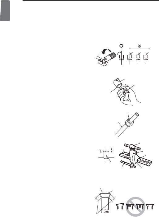
Preparation of Piping
Main cause of gas leakage is defect in flaring work. Carry out correct flaring work in the following procedure.
Cut the pipes and the cable
-Use the piping kit accessory or the pipes purchased locally.
-Measure the distance between the indoor and the outdoor unit.
-Cut the pipes a little longer than measured distance.
-Cut the cable 1.5 m longer than the pipe length.
Burrs removal
-Completely remove all burrs from the cut cross section of pipe/tube.
-Put the end of the copper tube/pipe in a downward direction as you remove burrs in order to avoid dropping burrs into the tubing.
Putting nut on
-Remove flare nuts attached to indoor and outdoor unit, then put them on pipe/tube having completed burr removal.
(not possible to put them on after flaring work)
Flaring work
-Carry out flaring work using flaring tool as shown below.
Outside diameter |
A |
|
mm |
inch |
mm |
Ø 6.35 |
1/4 |
1.1~1.3 |
Ø 9.52 |
3/8 |
1.5~1.7 |
Ø 12.7 |
1/2 |
1.6~1.8 |
Ø 15.88 |
5/8 |
1.6~1.8 |
Ø 19.05 |
3/4 |
1.9~2.1 |
Firmly hold copper pipe in a bar in the dimension shown in the table below.
Check
-Compare the flared work with figure below.
-If flare is noted to be defective, cut off the flared section and do flaring work again.
Copper
tube |
90 |
Slanted Uneven Rough |
Pipe
Reamer
Point down
Flare nut
Copper tube
|
Handle |
Bar |
Bar |
"A" |
Yoke |
|
Cone |
Copper pipe
Clamp handle
Red arrow mark
Smooth all round
Inside is shining without scratches.
= Improper flaring =
Inclined Surface Cracked Uneven
damaged thickness
Even length all round

CONNECTING PIPES 13
Connecting the pipes to the Outdoor unit
Align the center of the piping and sufficiently tighten the flare nut by hand.
Finally, tighten the flare nut with torque wrench until the wrench clicks.
- When tightening the flare nut with torque wrench, ensure the direction for tightening follows the arrow on the wrench.
Outside diameter |
Torque |
|
mm |
inch |
N·m |
Ø 6.35 |
1/4 |
16±2 |
Ø 9.52 |
3/8 |
38±4 |
Ø 12.7 |
1/2 |
55±6 |
Ø 15.88 |
5/8 |
75±7 |
Ø 19.05 |
3/4 |
110±10 |
η When tighten the pipe, hold the haxagonal body.
<![endif]>ENGLISH
Preventing foreign objects from entering
-Plug the pipe through-holes with putty or insulation material(procured locally)to stop up all gaps.
Torque wrench
Contin


 -uous
-uous 


ηWhen tighten the pipe, hold the haxagonal body.
Drain hose
 Connecting wire


 Gas side piping


 Liquid side piping

<![endif]>ENGLISH
14 CONNECTING PIPES |
|
|
|
Forming the Piping |
|
In cases where the Outdoor unit is installed |
|
Form the piping by wrapping the connecting |
above the Indoor unit perform the following. |
||
1 Tape the piping and connecting cable from |
|||
portion of the indoor unit with insulation mate- |
|||
down to up. |
|||
rial and secure it with two kinds of vinyl tape. |
|||
2 Secure the taped piping along the exterior |
|||
- If you want to connect an additional drain |
|||
wall. Form a trap to prevent water entering |
|||
hose, the end of the drain outlet should be |
|||
the room. |
|||
routed above the ground. Secure the drain |
|||
3 Fix the piping onto the wall by saddle or |
|||
hose appropriately. |
|
||
|
|
equivalent. |
|
In cases where the outdoor unit is installed |
Seal a small opening |
||
below the indoor unit perform the following. |
|||
1 Tape the piping, drain hose and connecting |
around the pipings |
||
with gum type sealanter. . |
|||
cable from down to up. |
|
Trap |
|
2 Secure the tapped piping along the exterior |
|||
|
|||
wall using saddle or equivalent. |
|
||
Seal a small |
|
Trap |
|
opening around |
|
||
the pipings with |
Taping |
|
|
gum type sealanter. . |
|
||
|
|
||
|
Drain hose |
|
|


 Plastic

 band
band
Pipings 
Connecting cable
Power supply cord
•Trap is required to prevent water from entering into electrical parts.

LEAKAGE TEST AND EVACUATION 15
LEAKAGE TEST AND EVACUATION
Air and moisture remaining in the refrigerant system have undesirable effects as indicated below.
-Pressure in the system rises.
-Operating current rises.
-Cooling(or heating) efficiency drops.
-Moisture in the refrigerant circuit may freeze and block capillary tubing.
-Water may lead to corrosion of parts in the refrigeration system.
Therefore, the indoor/outdoor unit and connecting tube must be checked for leak tight, and vacuumed to remove incondensible gas and moisture in the system.
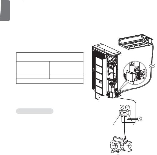
Preparation
Check that each tube(both liquid and gas side tubes) between the indoor and outdoor units have been properly connected and all wiring for the test run has been completed. Remove the service valve caps from both the gas and the liquid side on the outdoor unit. Check that both the liquid and the gas side service valves on the outdoor unit are kept closed at this stage.
Leakage test
Connect the manifold valve(with pressure gauges) and dry nitrogen gas cylinder to this service port with charge hoses.
! CAUTION
Be sure to use a manifold valve for leakage test. If it is not available, use a stop valve for this purpose. The "Hi" knob of the manifold valve must always be kept close.
-Pressurize the system to no more than 3.8 Mpa with dry nitrogen gas and close the cylinder valve when the gauge reading reached 3.8 MPa Next, test for leaks with liquid soap.
! CAUTION
To avoid nitrogen entering the refrigerant system in a liquid state, the top of the cylinder must be higher than its bottom when you pressurize the system. Usually, the cylinder is used in a vertical standing position.
-Do a leakage test of all joints of the tubing(both indoor and outdoor) and both gas and liquid side service valves.
Bubbles indicate a leak. Be sure to wipe off the soap with a clean cloth.
-After the system is found to be free of leaks, relieve the nitrogen pressure by loosening the charge hose connector at the nitrogen cylinder. When the system pressure is reduced to normal, disconnect the hose from the cylinder.
Indoor unit
Outdoor unit
Manifold valve
|
|
Pressure |
Lo |
Hi |
gauge |
|
|
Charge hose |
Nitrogen gas  cylinder(in vertical standing position)
<![endif]>ENGLISH
<![endif]>ENGLISH
16 LEAKAGE TEST AND EVACUATION |
|
||
Evacuation |
|
- Replace the valve caps at both gas and liquid |
|
- Connect the charge hose end described in |
side service valves and fasten them tight. |
||
This completes air purging with a vacuum pump. |
|||
the preceding steps to the vacuum pump to |
|||
The air conditioner is now ready to test run. |
|||
evacuate the tubing and indoor unit. |
|||
|
|||
Confirm the "Lo and Hi" knob of the manifold |
|
||
valve is open. Then, run the vacuum pump. |
Indoor unit |
||
The operation time for evacuation varies with |
|
||
tubing length and capacity of the pump. The |
|
||
following table shows the time required for |
|
||
evacuation. |
|
|
|
Required time for evacuation when 30 gal/h |
Outdoor unit |
||
vacuum pump is used |
|||
|
|||
If tubing length is |
If tubing length is |
|
|
longer than 10 m(33 |
|
||
less than 10 m(33 ft) |
|
||
ft) |
|
||
|
|
||
30 min. or more |
60 min. or more |
|
|
0.07 kPa or less |
|
||
- When the desired vacuum is reached, close the "Lo and Hi" knob of the manifold valve and stop the vacuum pump.
Manifold valve
Finishing the Job
-With a service valve wrench, turn the valve stem of liquid side valve counter-clockwise to fully open the valve.
-Turn the valve stem of gas side valve counterclockwise to fully open the valve.
-Loosen the charge hose connected to the gas side service port slightly to release the pressure, then remove the hose.
-Replace the flare nut and its bonnet on the gas side service port and fasten the flare nut securely with an adjustable wrench. This process is very important to prevent leakage from the system.
Lo |
Hi |
Pressure |
|
gauge |
|||
|
|
||
Open |
|
Open |
Vacuum pump
TEST RUNNING 17
TEST RUNNING
Precautions In Test Running
-The initial power supply must provide at least 90 % of the rated voltage. Otherwise, the air conditioner should not be operated.
!CAUTION
For test run, carry out the cooling operation firstly even during heating season. If heating operation is carried out firstly, it leads to the trouble of compressor. Then attention must be paid.
Carry out the test run more than 5 minutes without fail. (Test run will be cancelled 18 minutes later automatically)
-The test run is started by pressing the room temperature checking button and down timer button for 3 seconds at the same time.
-To cancel the test run, press any button.
CHECK THE FOLLOWING ITEMS WHEN INSTALLATION IS COMPLETE
-After completing work, be sure to measure and record trial run properties, and store measured data, etc.
-Measuring items are room temperature, outside temperature, suction temperature, blow out temperature, wind velocity, wind volume, voltage, current, presence of abnormal vibration and noise, operating pressure, piping temperature, compressive pressure.
-As to the structure and appearance, check following items.
□Is the circulation of air adequate? |
□Is the remote controller switch operated? |
|
□Is the draining smooth? |
□Is there any faulty wiring? |
|
□Is the heat insulation complete |
□Are not terminal screws loosened? |
|
(refrigerant and drain piping)? |
|
|
□Is there any leakage of refrigerant? |
M4...... |
118 N·cm {12 kgf·cm} |
|
M5...... |
196 N·cm {20 kgf·cm} |
|
M6...... |
245 N·cm {25 kgf·cm} |
|
M8...... |
588 N·cm {60 kgf·cm} |
Connection of power supply
•Connect the power supply cable to the independent power supply. - Circuit breaker is required.
•Operate the unit for fifteen minutes or more.
Evaluation of the performance
- Measure the temperature of the intake and discharge air.
- Ensure the difference between the intake temperature and the discharge one is more than 8 °C (Cooling) or reversely (Heating).
Thermometer
<![endif]>ENGLISH

<![endif]>ENGLISH
18 TEST RUNNING
! CAUTION
After the confirmation of the above conditions, prepare the wiring as follows:
1Never fail to have an individual power specialized for the air conditioner. As for the method of wiring, be guided by the circuit diagram pasted on the inside of control box cover.
2 Provide a circuit breaker switch between power source and the unit.
3The screw which fasten the wiring in the casing of electrical fittings are liable to come loose from vibrations to which the unit is subjected during the course of transportation. Check them and make sure that they are all tightly fastened. (If they are loose, it could give rise to burn-out of the wires.)
4 Specification of power source
5 Confirm that electrical capacity is sufficient.
6Be sure that the starting voltage is maintained at more than 90 percent of the rated voltage marked on the name plate.
7Confirm that the cable thickness is as specified in the power sources specification. (Particularly note the relation between cable length and thickness.)
8 Never fail to equip a leakage breaker where it is wet or moist.
9The following troubles would be caused by voltage drop-down.
-Vibration of a magnetic switch, damage on the contact point there of fuse breaking, disturbance to the normal function of a overload protection device.
-Proper starting power is not given to the compressor.

INSTALLATION GUIDE AT THE SEASIDE 19
INSTALLATION GUIDE AT THE SEASIDE
!CAUTION
•Air conditioners should not be installed in areas where corrosive gases, such as acid or alkaline gas, are produced.
•Do not install the product where it could be exposed to sea wind (salty wind) directly. It can result corrosion on the product. Corrosion, particularly on the condenser and evaporator fins, could cause product malfunction or inefficient performance.
•If outdoor unit is installed close to the seaside, it should avoid direct exposure to the sea wind. Otherwise it needs additional anticorrosion treatment on the heat exchanger.
Selecting the location(Outdoor Unit)
If the outdoor unit is to be installed close to the seaside, direct exposure to the sea wind should be avoided. Install the outdoor unit on the opposite side of the sea wind direction.
Sea wind
In case, to install the outdoor unit on the seaside, set up a windbreak not to be exposed to the sea wind.
Windbreak
Sea wind
-It should be strong enough like concrete to prevent the sea wind from the sea.
-The height and width should be more than 150 % of the outdoor unit.
-It should be keep more than 70 cm of space between outdoor unit and the windbreak for easy air flow.
Select a well-drained place.
•Periodic ( more than once/year ) cleaning of the dust or salt particles stuck on the heat exchanger by using water.
<![endif]>ENGLISH
Sea wind
<![endif]>ENGLISH
20 CONVENIENT FUNCTIONS
CONVENIENT FUNCTIONS
Pressure compensation function
MODEL NAME : ATUW48LMLS1, ATUW54LMLS1,ABUW48LM3S1, ABUW54LM3S1, APUW48LT3S1
If you use additional pipe to install the cooling operation, this function can compensate the target of pressure by setting dip switch.
*Pressure compensation function is release at initial state as standard.
*This function is used only if the length of pipe > 25 m, and be sure not to exceed the maximum length of pipe.
(It can be different depend on the model.)
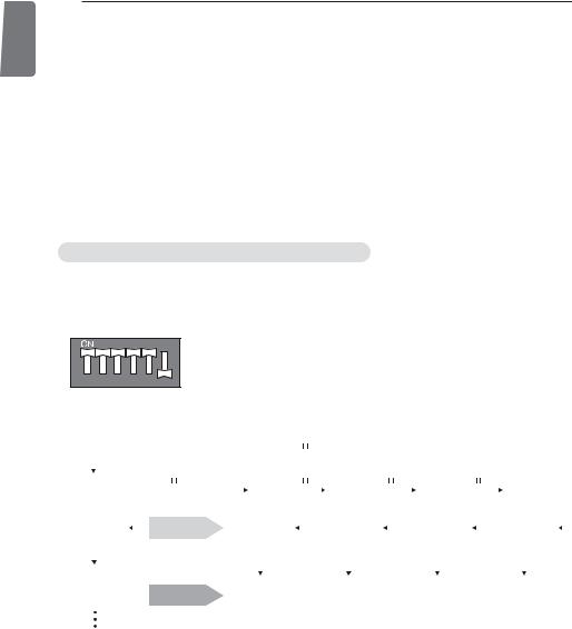
For setting pressure compensation function
Set the dip switch as follow after shutting the power source down. 1 Open the side panel or top cover of outdoor unit.
2 Set the DIP_SW01D like below image.
1 |
2 |
3 |
4 |
5 |
6 |
3 7 segments indicate each status and data like below image.
|
|
|
|
|
|
|
|
|
|
|
|
|
|
|
Press tact switch |
|
|
|
|
|
|
|
|
|
|
|
|
|
|
|
|
|
|
|
|
|
|||||||
|
|
|
|
|
|
|
|
|
|
|
|
|
|
|
|
|
|
|
|
|
|
|
|
|
|
|
|
|
|
|
|
|
|
|
|
|
|
|
|
|
|
|
|
|
|
|
|
|
|
|
|
|
|
|
|
|
|
|
|
|
|
|
|
|
|
|
|
|
|
|
|
|
|
|
|
|
|
|
|
|
|
|
|
|
|
|
|
|
|
|
|
|
|
Press tact switch |
|
Press tact switch |
Press tact switch |
Press tact switch |
|
|
|
||||||||||||||||||||||||||||||
Setting/Display/ |
|
|
|
|
|||||||||||||||||||||||||||||||||||||||
|
|
|
|
|
|
|
|
|
|
|
|
|
|
|
|
|
|
|
|
|
|
|
|
|
|
|
|
|
|
|
|
|
|
|
|
|
|
||||||
Communication |
|
|
|
|
Hz |
|
|
|
Current |
|
|
|
|
|
Voltage |
|
|
|
|
|
DC Link |
|
|
||||||||||||||||||||
|
|
|
|
|
|
|
|
|
|
|
|
|
|
|
|
|
|
|
|
|
|
|
|
|
|
|
|||||||||||||||||
|
|
status |
|
|
|
|
|
|
|
|
|
|
|
|
|
|
|
|
|
|
|
|
|
|
|
|
|
|
|
|
|
|
|
|
|
|
|||||||
|
|
|
Key letter |
|
|
|
|
|
|
|
|
|
|
|
|
|
|
|
|
|
|
|
|
|
|
|
|
|
|
|
|
|
|
|
|
|
|
||||||
|
|
|
|
|
|
|
|
|
|
|
|
|
|
|
|
|
|
|
|
|
|
|
|
|
|
|
|
|
|
|
|
|
|
|
|
|
|
|
|
|
|||
|
|
|
|
|
|
|
|
|
|
|
|
|
|
|
|
|
|
|
|
|
|
|
|
|
|
|
|
|
|
|
|
|
|
|
|
|
|
|
|
|
|||
|
|
|
|
|
|
|
|
|
|
|
|
|
|
|
|
|
|
|
|
|
|
|
|
|
|
|
|
|
|
|
|
|
|
|
|
|
|
|
|
|
|||
|
|
|
|
|
|
|
for each data |
|
|
|
|
|
|
|
|
|
|
|
|
|
|
|
|
|
|
|
|
|
|
|
|
|
|
|
|
|
|
|
|
|
|
||
|
|
|
|
|
|
|
|
|
|
|
|
|
|
|
|
|
|
|
|
|
|
|
|
|
|
|
|
|
|
|
|
|
|
|
|
|
|
|
|
|
|
|
|
|
|
|
|
|
|
|
|
|
|
|
|
|
|
|
|
|
|
|
|
|
|
|
|
|
|
|
|
|
|
|
|
|
|
|
|
|
|
|
|
|
|
|
|
|
|
|
|
|
|
|
|
|
|
0.5 sec |
|
|
0.5 sec |
|
0.5 sec |
|
0.5 sec |
|
0.5 sec |
|
0.5 sec |
|
0.5 sec |
|
0.5 sec |
||||||||||||||||||
|
|
|
|
|
|
|
|
|
|
|
off |
|
|
off |
|
off |
|
off |
|
|
off |
|
off |
|
|
off |
|
off |
|||||||||||||||
|
|
|
|
|
|
|
|
|
|
|
|
|
|
|
|||||||||||||||||||||||||||||
|
|
|
|
|
|
|
Indicating data |
|
|
|
|
|
|
|
|
|
|
|
|
|
|
|
|
|
|
|
|
|
|
|
|
|
|
|
|
|
|
|
|
|
|
||
|
|
|
|
|
|
|
|
|
|
|
|
|
|
|
|
|
|
|
|
|
|
|
|
|
|
|
|
|
|
|
|
|
|
|
|
|
|
|
|
|
|||
|
|
|
|
|
|
|
|
|
|
|
|
|
|
|
|
|
|
|
|
|
|
|
|
|
|
|
|
|
|
|
|
|
|
|
|
|
|
|
|
|
|||
|
|
|
|
|
|
|
for 0.5 sec |
|
|
|
|
|
|
|
|
|
|
|
|
|
|
|
|
|
|
|
|
|
|
|
|
|
|
|
|
|
|
|
|
|
|
||
|
|
|
|
|
|
|
|
|
|
|
|
|
|
|
|
|
|
|
|
|
|
|
|
|
|
|
|
|
|
|
|
|
|
|
|
|
|
|
|
|
|
|
|
|
|
|
|
|
|
|
|
|
|
|
|
|
|
|
|
|
|
|
|
|
|
|
|
|
|
|
|
|
|
|
|
|
|
|
|
|
|
|
|
|
|
|
|
|
|
|
|
|
|
|
|
|
|
|
|
|
|
|
|
|
|
|
|
|
|
|
|
|
|
|
|
|
|
|
|
|
|
|
|
|
|
|
|
|
|
|
|
|
|
|
|
|
|
|
|
|
|
|
|
|
|
|
|
|
|
|
|
|
|
|
|
|
|
|
|
|
|
|
|
|
|
|
|
|
|
|
|
|
|
|
|
|
|
|
|
|
|
|
|
|
|
|
|
|
|
|
|
|
|
|
|
|
|
|
|
|
|
|
|
|
|
|
|
|
|
|
|
|
|
|
|
|
|
|
|
|
|
|
|
|
|
|
|
|
|
|
|
|
|
|
|
|
|
|
|
|
|
|
|
|
|
|
|
|
|
|
|
|
|
|
|
|
|
|
|
|
|
|
|
|
|
|
|
|
|
|
|
|
|
|
|
|
|
|
|
|
|
|
|
|
|
|
|
|
|
|
|
|
|
|
|
|
|
|
|
|
|
|
|
|
|
|
|
<![endif]>FRANÇAIS
MANUEL D'INSTALLATION
CLIMATISEUR
Veuillez lire ce manuel dans son intégralité avant d'installer le climatiseur. L'installation doit être effectuée conformément aux normes électriques nationales par un personnel agréé uniquement.
Après avoir lu ce manuel attentivement, conservez-le pour pouvoir vous y reporter ultérieurement.
www.lg.com

<![endif]>FRANÇAIS
2 |
ASTUCES POUR ÉCONOMISER L’ÉNERGIE |
|
|
|
|
ASTUCES POUR ÉCONOMISER L’ÉNERGIE
Nous vous donnons ici quelques astuces qui vous permettront de minimiser la consommation d’énergie lorsque vous utilisez le climatiseur. Vous pouvez utiliser un climatiseur de manière plus efficace en vous référant aux instructions ci-dessous :
•Evitez un refroidissement excessif des unités intérieures. Cela pourrait mettre en danger votre santé et entraîner une plus grande consommation de l’électricité.
•Evitez d'exposer le climatiseur aux rayons solaires ; protégez-le à l’aide des rideaux ou des persiennes.
•Maintenez les portes et les fenêtres complètement fermées lorsque vous utilisez le climatiseur.
•Ajustez le sens de la circulation d’air verticalement ou horizontalement pour permettre la circulation de l’air intérieur.
•Accélérez le ventilateur pour refroidir ou réchauffer rapidement l’air intérieur en peu de temps.
•Ouvrez régulièrement des fenêtres pour des besoins d’aération étant donné que la qualité de l'air intérieur peut se détériorer si vous utilisez le climatiseur pendant plusieurs heures.
•Nettoyez le filtre à air une fois toutes les 2 semaines. La poussière et la saleté qui se sont accumulées à l’intérieur du filtre à air peuvent empêcher la circulation de l’air ou affaiblir les fonctions de refroidissement / déshumidification.
Pour vos archives
Agrafez votre reçu sur cette page; vous pourrez en avez besoin pour prouver la date d’achat ou pour des besoins de garantie. Ecrivez le numéro du modèle et le numéro de série ici:
Numéro du modèle :
Numéro de série :
Ces numéros se trouvent sur l’étiquette apposée sur le côté de chaque unité.
Nom du commerçant :
Date d’achat :

CONSIGNES IMPORTANTES DE SÉCURITÉ |
3 |
|
CONSIGNES DE SECURITE IMPORTANTES
LISEZ ENTIEREMENT LES INSTRUCTIONS AVANT D’UTILISER L’APPAREIL.
Respectez toujours les consignes suivantes pour éviter des situations dangereuses et garantir une performance optimale de votre produit.
! AVERTISSEMENT
Le non respect de ces consignes peut être fatal ou provoquer des blessures graves.
! ATTENTION
Le non respect de ces consignes peut provoquer des blessures légères ou endommager le produit.
! AVERTISSEMENT
•Les travaux d’installation ou de dépannage effectués par des personnes non qualifiées peuvent vous exposer aux risques en même temps que les autres personnes.
•L'installation doit être réalisée conformément aux normes locales en vigueur et effectuée uniquement par du personnel qualifié.
•Les informations contenues dans ce manuel sont destinées à un technicien de maintenance qualifié qui maîtrise les consignes de sécurité et dispose d’outils et d’instruments de test appropriés.
•Le fait de ne pas lire attentivement et de ne pas respecter les instructions de ce manuel peut provoquer un dysfonctionnement de l’équipement, des dégâts matériels, des blessures individuelles et/ou la mort.
Installation
•Mettez toujours à terre le produit. Autrement, vous risquez de provoquer un choc électrique.
•N'utilisez pas un cordon d’alimentation, une fiche d’alimentation ou une prise de courant endommagés. Autrement, vous risquez de causer un incendie ou un choc électrique.
•Pour l'installation du produit, contactez toujours le centre après-vente ou un service d’installation professionnel. Autrement, vous risquez de provoquer un incendie, un choc électrique, une explosion ou des blessures.
•Fixez correctement le couvercle de protection des pièces électriques à l’unité intérieure et le panneau de service à l’unité extérieure. Si le couvercle de protection des pièces électriques de l’unité intérieure et le panneau de service de l’unité extérieure ne sont pas bien fixés, cela peut provoquer un incendie ou un choc électrique dus à la poussière, à l’eau, etc.
•Installez toujours un interrupteur pour fuites d’air et un tableau électrique spécialisé. Ne pas le faire peut provoquer un incendie ou un choc électrique.
•Ne rangez ni n’utilisez de gaz inflammable ni de combustibles près du climatiseur. Autrement, vous risquez de provoquer un incendie ou le mauvais fonctionnement de l’appareil.
•Assurez-vous que le cadre d’installation de l’unité extérieure ne soit pas endommagé à cause d’une utilisation prolongée. Cela peut provoquer des blessures ou un accident.
•Ne démontez ni ne réparez le produit en n’importe quel point. Cela peut provoquer un incendie ou un choc électrique.
•Utilisez une pompe à vide ou un gaz Inerte (azote) lorsque vous faites des essais de fuite ou la purge d’air. Ne compressez pas l'air ou l'oxygène et n'utilisez pas de gaz inflammable. Cela pourrait provoquer un incendie ou une explosion. Risque de décès, de blessure, d'incendie ou d'explosion.
<![endif]>FRANÇAIS

|
4 |
CONSIGNES IMPORTANTES DE SÉCURITÉ |
|
|
|
|
|
|
• N'installez pas le produit dans un endroit d’où il puisse tomber. Autrement, vous risquez de |
||
|
|
||
|
|
blesser quelqu’un. |
|
|
|
• Soyez prudent pendant le déballage et l’installation. Les bords aiguisés peuvent provoquer |
|
| <![if ! IE]> <![endif]>FRANÇAIS |
|
des blessures. |
|
|
|
|
|
• N'allumez pas le disjoncteur ni l'alimentation lorsque le panneau frontal, le boîtier, le capot supérieur ou le couvercle du boîtier de commande sont retirés ou ouverts. À défaut, vous vous exposez à un risque d'incendie, de choc électrique, d'explosion ou de décès.
Fonctionnement
•Ne partagez pas la prise avec d’autres appareils. Cela peut provoquer un choc électrique ou un incendie à cause de la génération de chaleur.
•N'utilisez pas un cordon d’alimentation endommagé. Vous risquez de provoquer un incendie ou un choc électrique.
•Ne modifiez ni ne rallongez le cordon d’alimentation en n’importe quel point. Autrement, vous risquez de provoquer un incendie ou un choc électrique.
•Veillez à ce que le cordon d’alimentation ne soit pas tiré en cours de fonctionnement. Autrement, vous risquez de provoquer un incendie ou un choc électrique.
•Débranchez l’unité si vous constatez la présence de bruits étranges, d’odeurs ou de fumée provenant de l’appareil. Autrement, vous risquez de provoquer un incendie ou un choc électrique.
•Évitez le contact avec des flammes. Autrement, vous risquez de provoquer un incendie.
•A l’occasion, débranchez la fiche d’alimentation, en la prenant par la tête, et ne la touchez pas avec les mains mouillées. Autrement, vous risquez de provoquer un incendie ou un choc électrique.
•N`utilisez pas le cordon d’alimentation près des dispositifs de chauffage. Autrement, vous risquez de provoquer un incendie ou un choc électrique.
•N’ouvrez pas l’ouverture d’aspiration de l’unité intérieure/extérieure en cours de fonctionnement. Autrement, vous risquez de provoquer un choc électrique ou un mauvais fonctionnement.
•Ne permettez pas que de l’eau entre en contact avec les pièces électriques. Autrement, vous risquez de provoquer le mauvais fonctionnement de l’appareil ou un choc électrique.
•Prenez la fiche d’alimentation par la tête lorsque vous la débranchez. Cela peut provoquer un choc électrique ou des dommages.
•Ne touchez jamais les pièces métalliques de l’unité lorsque vous retirez le filtre. Elles sont aiguisées et peuvent provoquer des blessures.
•Ne montez sur l’appareil ni n’y placez aucun objet. Autrement, vous risquez de vous blesser en tombant de l’appareil.
•Ne placez pas d’objet lourd sur le cordon d’alimentation. Autrement, vous risquez de provoquer un incendie ou un choc électrique.
•Contactez le service après-vente si le produit est submergé dans l’eau. Autrement, vous risquez de causer un incendie ou un choc électrique.
•Veillez à ce que les enfants ne montent pas sur l’unité extérieure. Autrement, ils risquent d’être sérieusement blessés en tombant.

CONSIGNES IMPORTANTES DE SÉCURITÉ |
5 |
|
! ATTENTION
Installation
• Installez le raccord de drainage de manière à assurer un drainage convenable. Autrement, |
|
|
vous risquez de causer une fuite d'eau. |
<![if ! IE]> <![endif]>FRANÇAIS |
|
• Installez le produit de sorte que vos voisins ne soient pas dérangés par le bruit ou par le vent |
||
|
||
chaud venant de l'unité extérieure. Autrement, vous risquez de susciter des querelles avec |
|
|
les voisins. |
|
|
• Après l’installation ou la réparation du produit, veillez toujours à vérifier qu’il n’y ait pas de |
|
|
fuite de gaz. Autrement, vous risquez de causer le mauvais fonctionnement de l'appareil. |
|
|
• Maintenez le niveau lors de l’installation du produit. Autrement, vous risquez de provoquer |
|
|
des vibrations ou une fuite d'eau. |
|
Fonctionnement
•Évitez le refroidissement excessif et aérez parfois. Autrement, vous risquez de nuire à votre santé.
•Utilisez un tissu doux pour nettoyer l’appareil. N'employez ni de cire, ni de diluant ni de détergent fort. Autrement, vous risquez de détériorer l’aspect de l’appareil, changer sa couleur ou provoquer des défauts sur sa surface.
•N'utilisez pas le produit à des buts particuliers, tels que la préservation d’animaux, de plantes, de dispositifs de précision ou d’objets d'art, etc. Autrement, vous risquez d’endommager vos biens.
•Ne placez pas d'obstacles autour de l'entrée ou de la sortie du flux d’air. Autrement, vous risquez de provoquer le mauvais fonctionnement de l’appareil ou un accident.
 Loading...