How it Works
Log In / Sign Up
Buy Points
How it Works
FAQ
Contact Us
Questions and Suggestions
Users
LG
Loading...
A
ABNQ18GL2A2
2
ABNQ18GM1T1
6
ABNQ18GM1T2
2
ABNQ21GHLA0
ABNQ21GL2A0
ABNQ22GM1A4
4
ABNQ24GGLA0
2
ABNQ24GM1A2
2
ABNQ36GM3A4
ABNQ42GM3T2
4
ABNQ48GM3A2
4
ABNQ48GRLA0
2
ABNQ54GM3T1
3
ABNQ60LM3T1
6
ABNW12GL5S1
2
ABNW18GBHC0
ABNW18GM1S1
8
ABNW24GBHC0
ABNW24GGLT0
5
ABNW24GM1A0
4
ABNW24GM1E4
4
ABNW24GM1S1
4
ABNW27GM1T1
2
ABNW366KSA1
ABNW366KSA3
2
ABNW36GM2A0
ABNW36GM2S1
3
ABNW426KSA1
ABNW426KSA3
2
ABNW486KSA1
2
ABNW48LM3S1
7
ABNW50LM3S1
2
ABNW54GRLT0
3
ABNW606LTA1
2
ABNW60LM3S1
ABNW85GB9A0
ABR521
3
ABUH4287SS1
ABUM1400WT4
ABUQ18GHLA0
3
ABUQ18GL2A0
ABUQ18GL2A2
ABUQ21GHLA0
2
ABUQ21GL2A0
ABUQ24GGLA0
2
ABUQ24GL3A0
ABUQ30GM1A4
ABUQ30GM1T1
6
ABUQ42GM3T2
2
ABUQ60LM3T1
3
ABUW12GL5S1
ABUW18GM1S1
3
ABUW24GM1E4
2
ABUW24GM1S1
ABUW3066SS0
ABUW3666SS1
ABUW366KSA0
ABUW366KSA1
2
ABUW366KSA3
2
ABUW36GM2S1
2
ABUW426KSA1
2
ABUW426KSA3
ABUW486KSA0
ABUW486KSA1
2
ABUW48LM3S1
ABUW5567SS1
ABUW606LTA0
ABUW606LTA1
3
ABUW60LM3S1
ABV341
2
ABV441
2
ABV511
ABWPEVN
ABZCA
8
AC09BH
4
AC09BQ
3
AC09BT
AC12BQ
3
AC200I
AC201P
AC209I
AC21
AC220P
2
AC24BQ
AC250I
AC250W
AC259I
AC270P
2
AC270Y
3
AC280Y
AC401P
AC-923-A - DOORBELL SB/PEWTER LTD
2
AC Ez
AC Ez Touch
AC Smart
2
AC Smart 5
AC Smart BACnet
AC Smart II
AC Smart IV
AC Smart Premium PQCSW421E0A
Loading...
Loading...
Nothing found
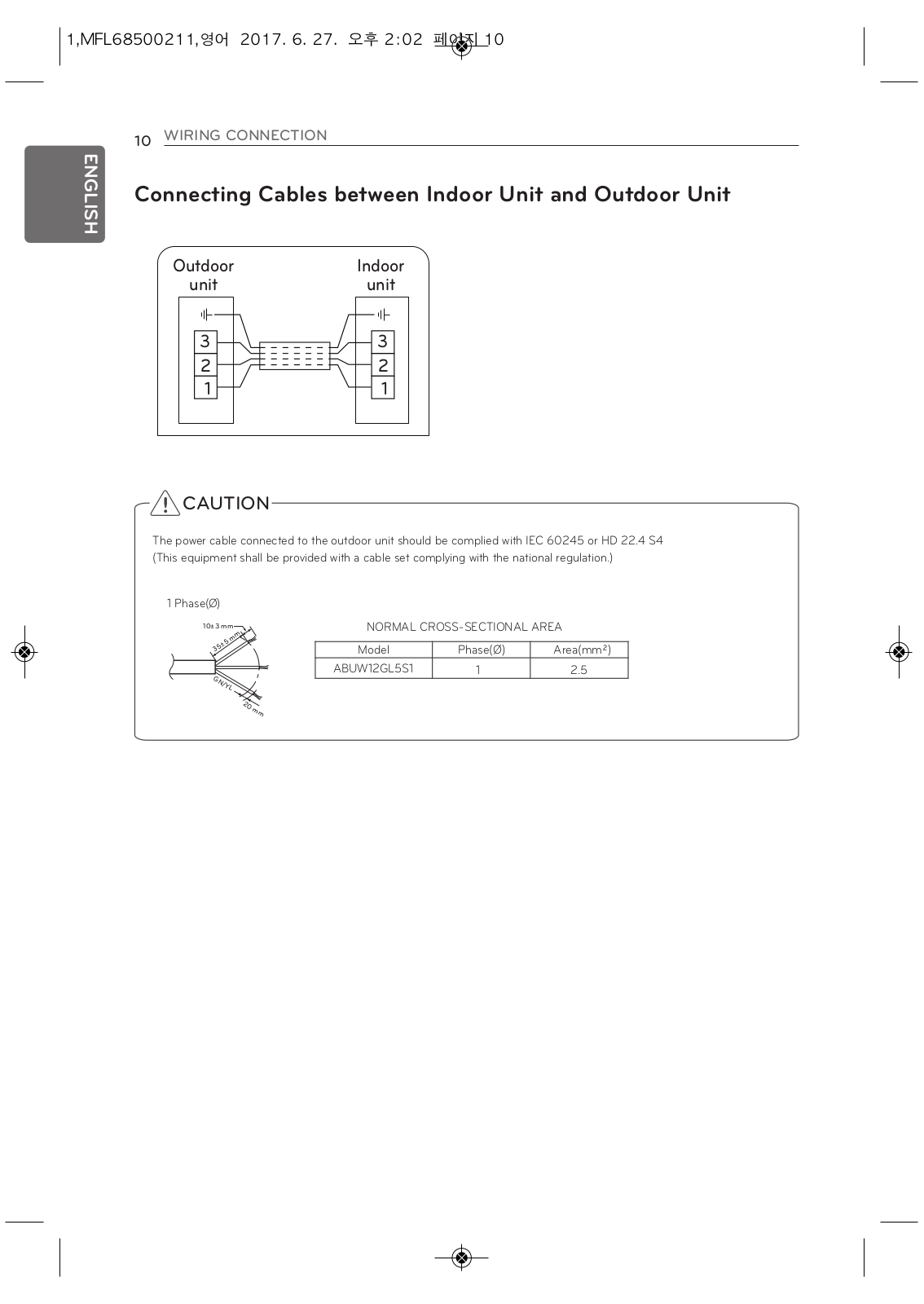
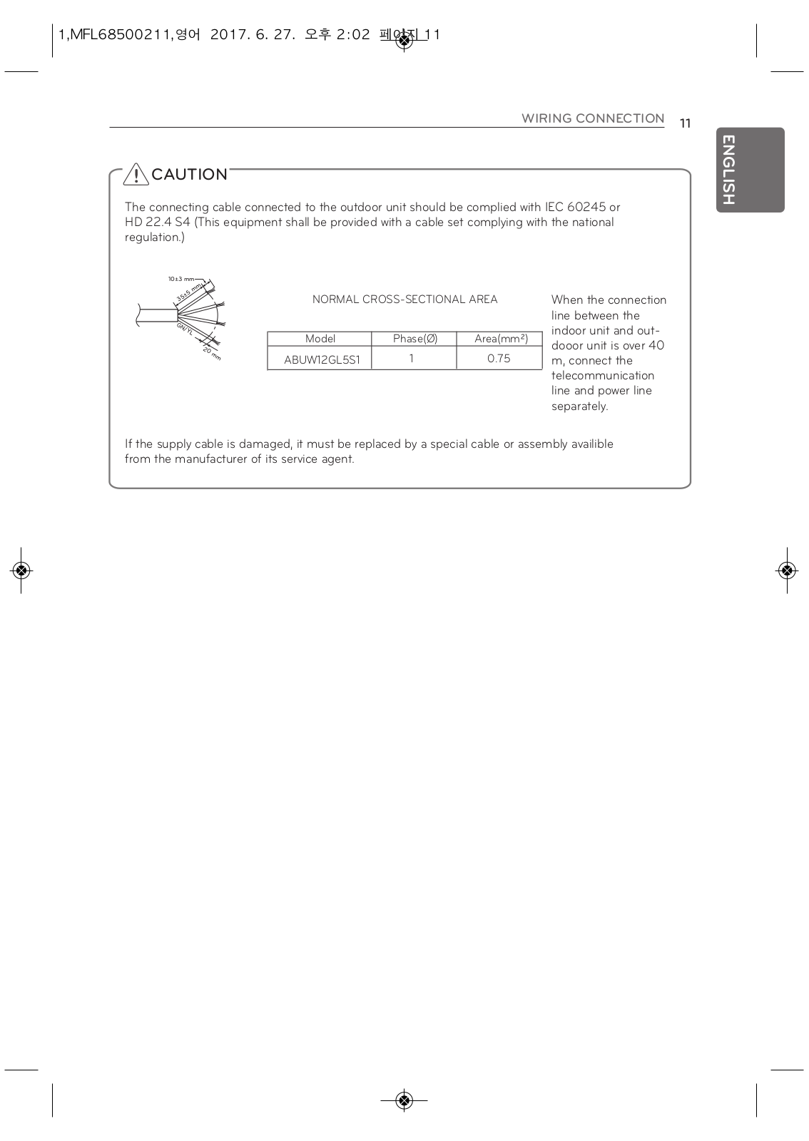
ABUW12GL5S1
INSTALLATION MANUAL
63 pgs
15.24 Mb
0
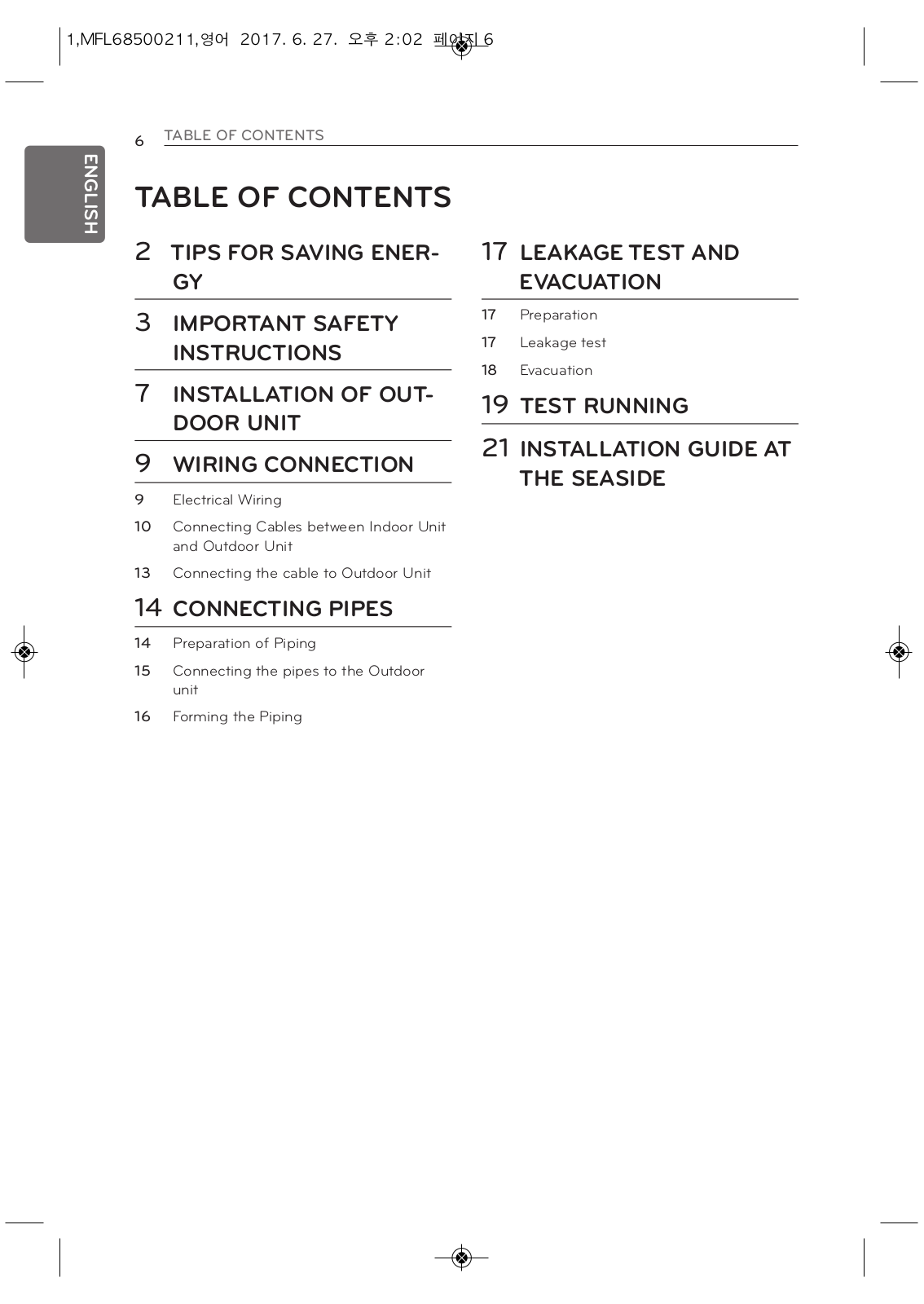
Table of contents
Loading...
LG ABUW12GL5S1 INSTALLATION MANUAL
...
LG INSTALLATION MANUAL
Download
Specifications and Main Features
Frequently Asked Questions
User Manual
Download
Loading...
+
44
hidden pages
Unhide
You need points to download manuals.
1 point = 1 manual.
You can buy points or you can get point for every manual you upload.
Buy points
Upload your manuals
 Loading...