

LG ABNW24GM1A0 INSTALLATION MANUAL
MFL67939931
Rev.01_121918
Please read this installation manual completely before installing the product.
Installation work must be performed in accordance with the national wiring standards by
authorized personnel only.
Please retain this installation manual for future reference after reading it thoroughly.
Ceilling Concealed Duct
Original instruction
INSTALLATION MANUAL
AIR
CONDITIONER
www.lg.com
Copyright © 2017 - 2018 LG Electronics Inc. All Rights Reserved.
ESPAÑOLENGLISH

2
Single A Air Conditioner Installation Manual
CONTENTS
Safety Precautions ..............................................................................................3
Model Designation...............................................................................................6
External Appearance ...........................................................................................7
Installation Places ...............................................................................................8
The indoor unit installation...............................................................................10
Remote Controller Installation .........................................................................21
Optional Operation ............................................................................................24
How to Set E.S.P?..............................................................................................32
Self-diagnosis Function ....................................................................................39
Dip Switch Setting .............................................................................................39
Safety Precautions
Installation Manual 3
ENGLISH
Safety Precautions
To prevent the injury of the user or other people and property damage, the following instructions must be followed.
n Be sure to read before installing the air conditioner.
n Be sure to observe the cautions specified here as they include important items related to safety.
n Incorrect operation due to ignoring instruction will cause harm or damage. The seriousness is classified by the
following indications.
n The meanings of the symbols used in this manual are as shown below.
This symbol indicates the possibility of death or serious injury.
This symbol indicates the possibility of injury or damage to properties only.
Be sure not to do.
Be sure to follow the instruction.
Installation
• Do not use a defective or underrated circuit breaker. Use this appliance on a dedicated circuit.
- There is risk of fire or electric shock.
• For electrical work, contact the dealer, seller, a qualified electrician, or an Authorized Service Center.
- Do not disassemble or repair the product. There is risk of fire or electric shock.
• Always ground the product.
- There is risk of fire or electric shock.
• Install the panel and the cover of control box securely.
- There is risk of fire or electric shock.
• Always install a dedicated circuit and breaker.
- Improper wiring or installation may cause fire or electric shock.
• Use the correctly rated breaker or fuse.
- There is risk of fire or electric shock.
• Do not modify or extend the power cable.
- There is risk of fire or electric shock.
• Do not install, remove, or re-install the unit by yourself (customer).
- There is risk of fire, electric shock, explosion, or injury.
• Be cautious when unpacking and installing the product.
- Sharp edges could cause injury. Be especially careful of the case edges and the fins on the condenser
and evaporator.
• For installation, always contact the dealer or an Authorized Service Center.
- There is risk of fire, electric shock, explosion, or injury.
• Do not install the product on a defective installation stand.
- It may cause injury, accident, or damage to the product.
• Be sure the installation area does not deteriorate with age.
- If the base collapses, the air conditioner could fall with it, causing property damage, product failure, and
personal injury.
• Do not turn on the breaker or power under condition that front panel, cabinet, top cover, control box
cover are removed or opened.
WARNING
CAUTION
!
!
WARNING
!
4
Safety Precautions
- Otherwise, it may cause fire, electric shock, explosion or death.
• Use a vacuum pump or Inert (nitrogen) gas when doing leakage test or air purge. Do not compress air or
Oxygen and Do not use Flammable gases. Otherwise, it may cause fire or explosion.
- There is the risk of death, injury, fire or explosion.
Operation
• Do not let the air conditioner run for a long time when the humidity is very high and a door or a window is
left open.
- Moisture may condense and wet or damage furniture.
• Take care to ensure that power cable could not be pulled out or damaged during operation.
- There is risk of fire or electric shock.
• Do not place anything on the power cable.
- There is risk of fire or electric shock.
• Do not touch(operate) the product with wet hands.
- There is risk of fire or electrical shock.
• Do not place a heater or other appliances near the power cable.
- There is risk of fire and electric shock.
• Do not allow water to run into electric parts.
- It may cause There is risk of fire, failure of the product, or electric shock.
• Do not store or use flammable gas or combustibles near the product.
- There is risk of fire or failure of product.
• Do not use the product in a tightly closed space for a long time.
- Oxygen deficiency could occur.
• When flammable gas leaks, turn off the gas and open a window for ventilation before turn the product on.
- Do not use the telephone or turn switches on or off. There is risk of explosion or fire.
• If strange sounds, or smell or smoke comes from product. Turn the breaker off or disconnect the power
supply cable.
- There is risk of electric shock or fire.
• Stop operation and close the window in storm or hurricane. If possible, remove the product from the
window before the hurricane arrives.
- There is risk of property damage, failure of product, or electric shock.
• Do not open the inlet grill of the product during operation. (Do not touch the electrostatic filter, if the unit
is so equipped.)
- There is risk of physical injury, electric shock, or product failure.
• When the product is soaked (flooded or submerged), contact an Authorized Service Center.
- There is risk of fire or electric shock.
• Be cautious that water could not enter the product.
- There is risk of fire, electric shock, or product damage.
• Ventilate the product from time to time when operating it together with a stove, etc.
- There is risk of fire or electric shock.
• Turn the main power off when cleaning or maintaining the product.
- There is risk of electric shock.
• When the product is not be used for a long time, disconnect the power supply plug or turn off the breaker.
- There is risk of product damage or failure, or unintended operation.
• Take care to ensure that nobody could step on or fall onto the outdoor unit.
- This could result in personal injury and product damage.
CAUTION
!

Installation Manual 5
Safety Precautions
ENGLISH
Installation
• Always check for gas (refrigerant) leakage after installation or repair of product.
- Low refrigerant levels may cause failure of product.
• Install the drain hose to ensure that water is drained away properly.
- A bad connection may cause water leakage.
• Keep level even when installing the product.
- To avoid vibration or water leakage.
• Do not install the product where the noise or hot air from the outdoor unit could damage the
neighborhoods.
- It may cause a problem for your neighbors.
• Use two or more people to lift and transport the product.
- Avoid personal injury.
• Do not install the product where it will be exposed to sea wind (salt spray) directly.
- It may cause corrosion on the product. Corrosion, particularly on the condenser and evaporator fins,
could cause product malfunction or inefficient operation.
Operation
• Do not expose the skin directly to cool air for long periods of time. (Don't sit in the draft.)
- This could harm to your health.
• Do not use the product for special purposes, such as preserving foods, works of art, etc. It is a consumer
air conditioner, not a precision refrigeration system.
- There is risk of damage or loss of property.
• Do not block the inlet or outlet of air flow.
- It may cause product failure.
• Use a soft cloth to clean. Do not use harsh detergents, solvents, etc.
- There is risk of fire, electric shock, or damage to the plastic parts of the product.
• Do not touch the metal parts of the product when removing the air filter. They are very sharp!
- There is risk of personal injury.
• Do not step on or put anything on the product. (outdoor units)
- There is risk of personal injury and failure of product.
• Always insert the filter securely. Clean the filter every two weeks or more often if necessary.
- A dirty filter reduces the efficiency of the air conditioner and could cause product malfunction or
damage.
• Do not insert hands or other objects through the air inlet or outlet while the product is operated.
- There are sharp and moving parts that could cause personal injury.
• Do not drink the water drained from the product.
- It is not sanitary and could cause serious health issues.
• Use a firm stool or ladder when cleaning or maintaining the product.
- Be careful and avoid personal injury.
• Replace the all batteries in the remote control with new ones of the same type. Do not mix old and new
batteries or different types of batteries.
- There is risk of fire or explosion.
• Do not recharge or disassemble the batteries. Do not dispose of batteries in a fire.
- They may burn or explode.
• If the liquid from the batteries gets onto your skin or clothes, wash it well with clean water. Do not use the
remote if the batteries have leaked.
- The chemicals in batteries could cause burns or other health hazards.
• If you eat the liquid from the batteries, brush your teeth and see doctor. Do not use the remote if the
batteries have leaked.
- The chemicals in batteries could cause burns or other health hazards.

6
Model Designation
Product information
- Product Name : Air conditioner.
- Additional Information : serial number is refer to the barcode on the product.
- Max allowable pressure High side : 4.2 MPa / Low side : 2.4 MPa
- Refrigerant : R410A
Model Designation
Limiting concentration is the limit of Freon gas concentration where immediate measures
can be taken without hurting human body when refrigerant leaks in the air. The limiting
concentration shall be described in the unit of kg/m
3
(Freon gas weight per unit air volume)
for facilitating calculation
n Calculate refrigerant concentration
Refrigerant
concentration (kg/m
3
)
Limiting concentration
The A-weighted sound pressure emitted by this product is below 70 dB.
** The noise level can vary depending on the site.
The figures quoted are emission level and are not necessarily safe working levels.
Whilst there is a correlation between the emission and exposure levels, this cannot be
used reliably to determine whether or not further precautions are required.
Factor that influence the actual level of exposure of the workforce include the
characteristics of the work room and the other sources of noise, i.e. the number of
equipment and other adjacent processes and the length of time for which an operator
exposed to the noise. Also, the permissible exposure level can vary from country to
country.
This information, however, will enable the user of the equipment to make a better
evaluation of the hazard and risk.
Airborne Noise Emission
Total amount of replenished refrigerant in refrigerant facility (kg)
Capacity of smallest room where indoor unit is installed (m
3
)
Limiting concentration: 0.44 kg/m3(R410A)
=
External Appearance
Installation Manual 7
ENGLISH
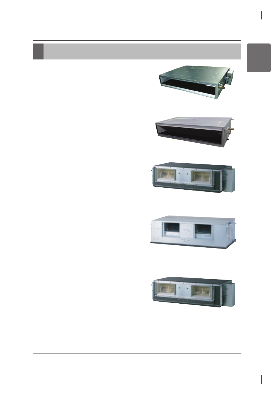
External Appearance
• Ceiling Concealed Duct – Low static pressure
L1/L2/L3 Chassis
• Ceiling Concealed Duct – Mid static pressure
M1/M2/M3 Chassis
• Ceiling Concealed Duct – H-INV
BR Chassis
• Ceiling Concealed Duct – Compact
BH Chassis
• Celling Concealed Duct – High static pressure
B8 Chassis
8
Installation Places
Ceiling Concealed Duct – Low Static Ceiling Concealed Duct – Mid Static
Ceiling Concealed Duct – Compact
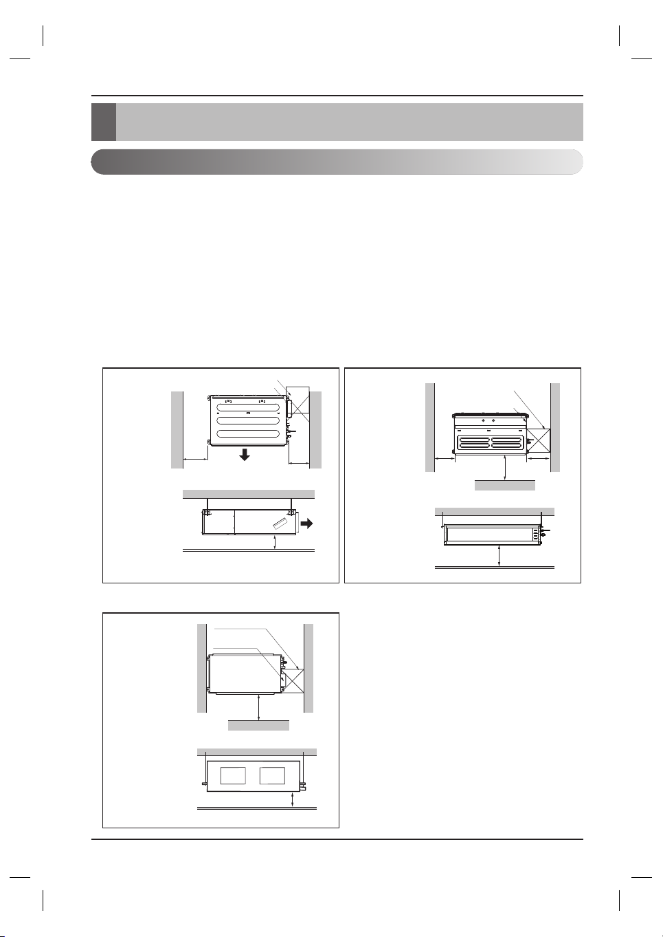
Installation Places
Install the air conditioner in the location that satisfies the following conditions.
• The place shall easily bear a load exceeding four times the indoor unit’s weight.
• The place shall be able to inspect the unit as the figure.
• The place where the unit shall be leveled.
•
The place shall allow easy water drainage.
(Suitable dimension “H” is necessary to get a slope to drain as figure.)
• The place shall easily connect with the outdoor unit.
• The place where the unit is not affected by an electrical noise.
• The place where air circulation in the room will be good .
• There should not be any heat source or steam near the unit.
Inspection hole (600 x 600)
Control box
H=20 or more
• Suitable dimension "H" is necessary to get a slope
to drain as shown in the figure
600
600
Air outlet
Air outlet
Top view
(unit: mm)
Front view
Inspection hole
(600 x 600)
Control box
1 000
H
600
600
Front
Top view
(unit: mm)
(unit: mm)
Side view
Top view
(unit: mm)
Front view
H
Front
Inspection hole
(600 x 600)
Control box
1 000
Selection of the best location
Installation Places
Installation Manual 9
ENGLISH
CAUTION
In case that the unit is installed near the sea, the installation parts may be
corroded by salt, The installation parts (and the unit) should be taken appropriate
anti-corrosion measures.
!
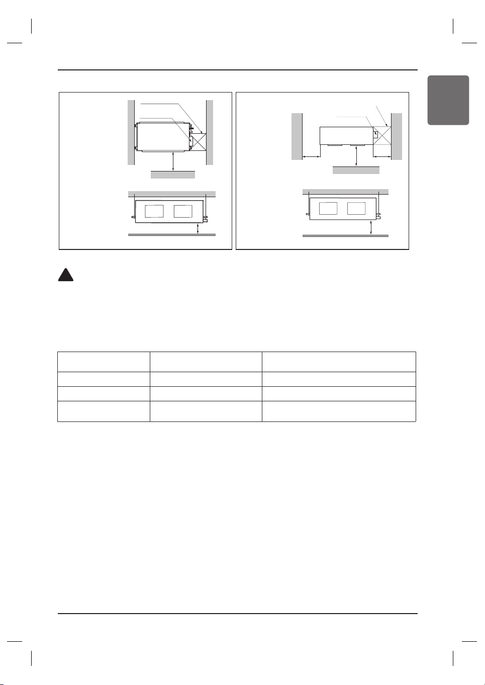
[Inspection Hole Standard]
Number of
Inspection hole
Distance between
False ceiling & Actual ceiling
Remarks
1 More than 100 cm
Sufficient space in the ceiling for servicing.
2 20 cm to 100 cm
Insufficient space. Difficult for servicing
Hole size should be more
than the size of IDU.
Less than 20 cm
Minimum height for motor replacement.
Ceiling Concealed Duct – H-INV Ceiling Concealed Duct – High Static
Top view
(unit: mm)
Front view
Top view
(unit: mm)
Front view
H
Front
Inspection hole
(600 x 600)
Control box
1 000
1 000
H
600 600
Front
Inspection hole (600X600)
Control box
10
The indoor unit installation
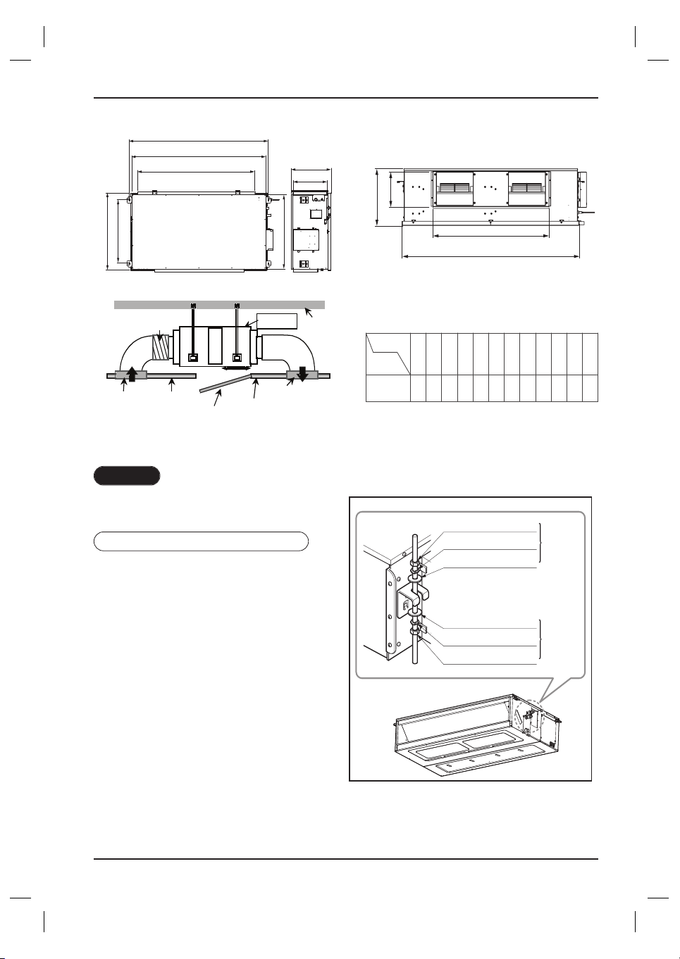
The indoor unit installation
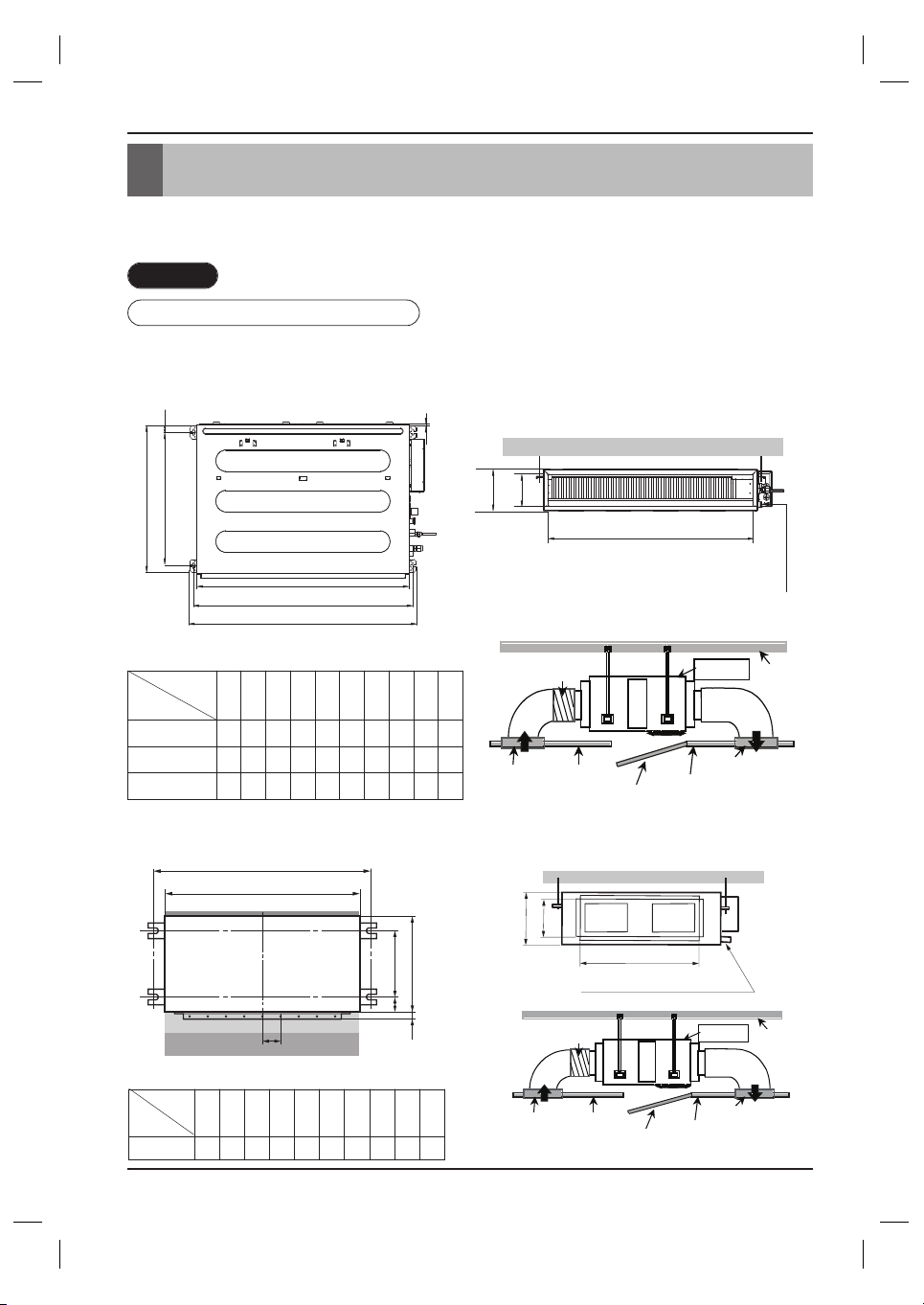
Installation of Unit
Install the unit above the ceiling correctly.
CASE 1
POSITION OF SUSPENSION BOLT
• Apply a joint-canvas between the unit and duct to absorb unnecessary vibration.
• Apply a filter Accessory at air return hole.
C
E
G
D
F
I
A
J
B
H
Drainage hole
(Unit: mm)
Dimension
Capacity
(kBtu/h)
A B C D E F G H I J
9
733 772 628 700 36 190 20 660 155 700
12/18
933 972 628 700 36 190 20 860 155 900
24
1 133 1 172 628 700 36 190 20 1 060 155 1 100
Ceiling Concealed Duct – Low Static
Ceiling Concealed Duct – Compact
(Unit:mm)
A B C D E F (G) H I J
18/24
932 882 355 46 450 30 87 750 163 260
Dimension
Capacity(kBtu/h)
Inspection
Port
Indoor Unit
Ceiling
Canvas
Duct
Air Intake
Port
Ceiling
Board
Ceiling Board
Air Discharge
Port
Discharge
Flexible Duct
Intake
Duct
A
B
CD
(G)
EF
body
filter
Joint canvas
Main duct
Drainage hole
Inspection
Port
Indoor Unit
Ceiling
Canvas
Duct
Air Intake
Port
Ceiling
Board
Ceiling Board
Air Discharge
Port
Discharge
Flexible Duct
Intake
Duct
H
I
J
The indoor unit installation
Installation Manual 11
ENGLISH
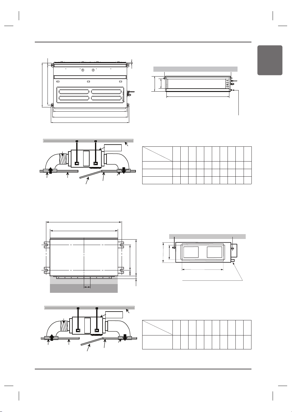
Drainage hole
C
E
G
D
F
I
A
J
B
H
Inspection
Port
Indoor Unit
Ceiling
Canvas
Duct
Air Intake
Port
Ceiling
Board
Ceiling Board
Air Discharge
Port
Discharge
Flexible Duct
Intake
Duct
Ceiling Concealed Duct – Mid Static
(Unit:mm)
ABCDEFGHI J
18 / 24 / 30
933.4 971.6 619.2 700 30 270 15.2 858 201.4 900
36 / 42
1 283.4 1 321.6 619.2 689.6 30 270 15.2 1 208 201.4 1 250
48 / 60
1 283.4 1 321.6 619.2 689.6 30 360 15.2 1 208 291.4 1 250
Dimension
Capacity
(kBtu/h)
Drainage hole
A
B
CD
(G)
EF
body
filter
Joint canvas
Main duct
H
I
J
Inspection
Port
Indoor Unit
Ceiling
Canvas
Duct
Air Intake
Port
Ceiling
Board
Ceiling Board
Air Discharge
Port
Discharge
Flexible Duct
Intake
Duct
Ceiling Concealed Duct – H-INV
(Unit:mm)
A B C D E F (G) H I J
36 / 42 / 46
1 290 1 230
447 56 590 30 120
1 006
294 380
Dimension
Capacity (kBtu/h)
12
The indoor unit installation
H
K
G
EF
L
I
J
B
A
C
D
Inspection
Port
Indoor Unit
Ceiling
Canvas
Duct
Air Intake
Port
Ceiling
Board
Ceiling Board
Air Discharge
Port
Discharge
Flexible Duct
Intake
Duct
Ceiling Concealed Duct – High Static
(Unit:mm)
Dimension
Capacity
(kBtu/h)
A B C D E F G H I J K L
70
85
1 594 1 044 286 460 580 713 1 368 1 622 392 458 1 563 791
CASE 2
• Install the unit leaning to a drainage hole
side as a figure for easy water drainage.
• A place where the unit will be leveled
and that can support the weight of the
unit.
• A place where the unit can withstand its
vibration.
• A place where service can be easily
performed.
POSITION OF CONSOLE BOLT
M10 Nut
M10 SP. washer
M10 washer
M10 washer
M10 SP. washer
M10 Nut
X 4
X 4
X 4
X 4
X 4
X 4
(Local
supply)
(Local
supply)
The indoor unit installation
Installation Manual 13
ENGLISH
CAUTION
Tighten the nut and bolt top revent unit falling.
!
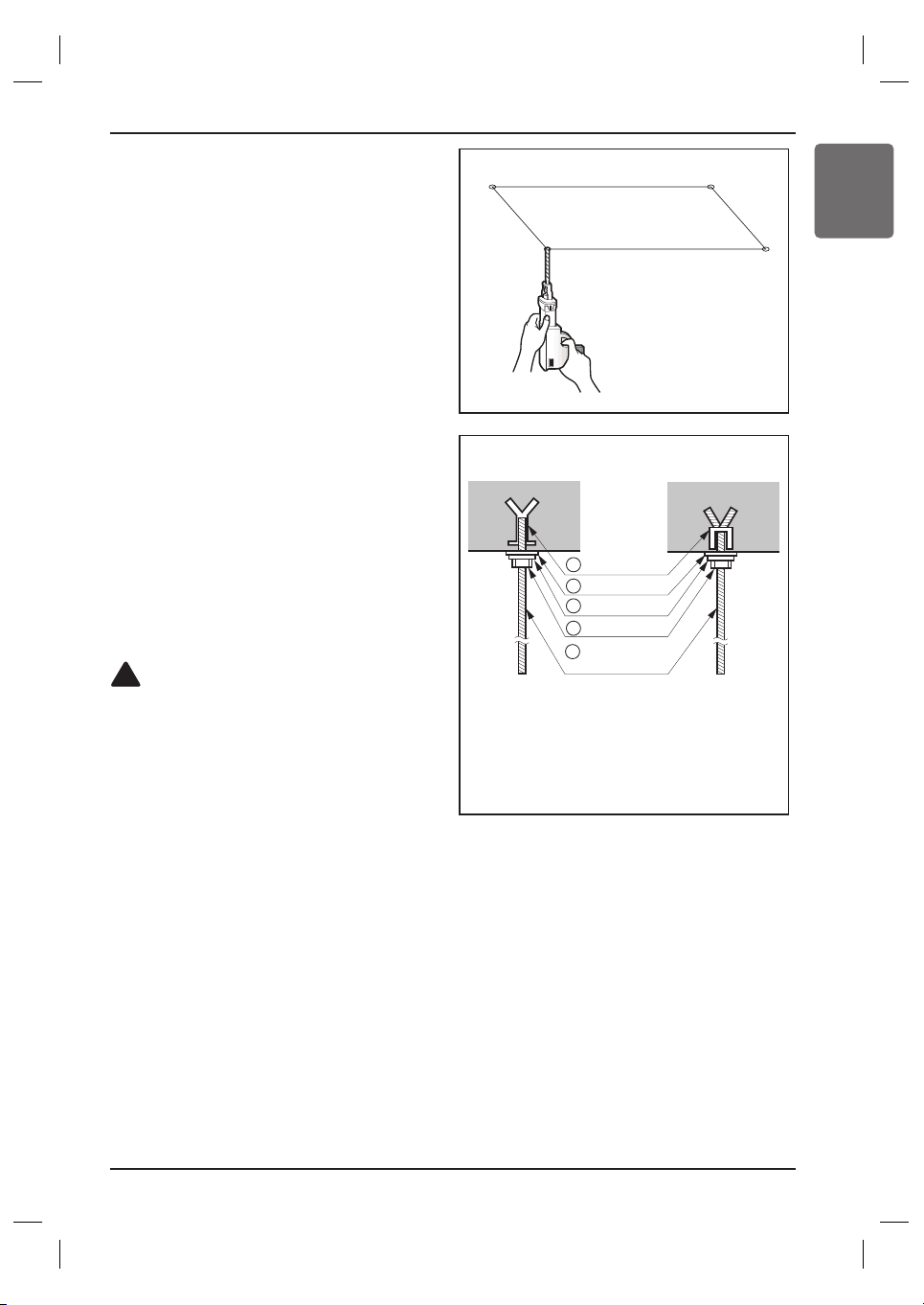
• Select and mark the position for fixing
bolts.
• Drill the hole for set anchor on the face of
ceiling.
• Insert the set anchor and washer onto the
suspension bolts for locking the
suspension bolts on the ceiling.
• Mount the suspension bolts to the set
anchor firmly.
• Secure the installation plates onto the
suspension bolts (adjust level roughly)
using nuts, washers and spring washers.
• Local supply
① Set anchor
② Plate washer - M10
③ Spring washer - M10
④ Nut - W3/8 or M10
⑤ Suspension bolt - W3/8 or M10
Old building New building
1 Set anchor
2 Plate washer
3 Spring washer
4 Nut
5 Suspension
bolts
 Loading...