

LG ABNQ60LM3T1 Installation Manual

MFL67939936
Rev.05_111220
INSTALLATION MANUAL
Ceiling Concealed Duct
AIR
CONDITIONER
www.lg.com
Please read this installation manual completely before installing the product.
Installation work must be performed in accordance with the national wiring
standards by authorized personnel only.
Please retain this installation manual for future reference after reading it
thoroughly.
Copyright © 2018 - 2020 LG Electronics Inc. All Rights Reserved.
ENGLISH
FRANÇAIS
TIPS FOR SAVING ENERGY
2
ENGLISH
TIPS FOR SAVING ENERGY
Here are some tips that will help you minimize the power consumption when you use the air
conditioner. You can use your air conditioner more efficiently by referring to the instructions
below:
• Do not cool excessively indoors. This may be harmful for your health and may consume more
electricity.
• Block sunlight with blinds or curtains while you are operating the air conditioner.
• Keep doors or windows closed tightly while you are operating the air conditioner.
• Adjust the direction of the air flow vertically or horizontally to circulate indoor air.
• Speed up the fan to cool or warm indoor air quickly, in a short period of time.
• Open windows regularly for ventilation as the indoor air quality may deteriorate if the air
conditioner is used for many hours.
• Clean the air filter once every 2 weeks. Dust and impurities collected in the air filter may block the
air flow or weaken the cooling / dehumidifying functions.
For your records
Staple your receipt to this page in case you need it to prove the date of purchase or for warranty
purposes. Write the model number and the serial number here:
Model number :
Serial number :
You can find them on a label on the side of each unit.
Dealer’s name :
Date of purchase :
IMPORTANT SAFETY INSTRUCTIONS
IMPORTANT SAFETY INSTRUCTIONS
READ ALL INSTRUCTIONS BEFORE USING THE APPLIANCE.
Always comply with the following precautions to avoid dangerous situations and ensure peak
performance of your product.
WARNING
!
It can result in serious injury or death when the directions are ignored.
CAUTION
!
It can result in minor injury or product damage when the directions are ignored.
WARNING
!
• Installation or repairs made by unqualified persons can result in hazards to you and others.
• Installation of all field wiring and components MUST conform with local building codes or, in
the absence of local codes, with the National Electrical Code 70 and the National Building
Construction and Safety Code or Canadian Electrical code and National Building Code of
Canada.
• The information contained in the manual is intended for use by a qualified service technician
familiar with safety procedures and equipped with the proper tools and test instruments.
• Failure to carefully read and follow all instructions in this manual can result in equipment
malfunction, property damage, personal injury and/or death.
Installation
• Always perform grounding.
- Otherwise, it may cause electrical shock.
• For installation of the product, always contact the service center or a professional installation
agency.
- Otherwise, it may cause a fire, electrical shock, explosion or injury.
• Securely attach the electrical part cover to the indoor unit and the service panel to the outdoor unit.
- If the electrical part cover of the indoor unit and the service panel of the outdoor unit are not
attached securely, it could result in a fire or electric shock due to dust, water, etc.
• Always install an earth leakage circuit breaker and a dedicated switching board.
- No installation may cause a fire and electrical shock.
• Do not keep or use flammable gases or combustibles near the air conditioner.
- Otherwise, it may cause a fire or the failure of product.
• Ensure that an installation frame of the outdoor unit is not damaged due to use for a long time.
- It may cause injury or an accident.
• Do not disassemble or repair the product randomly.
- It will cause a fire or electrical shock.
• Do not install the product at a place that there is concern of falling down.
- Otherwise, it may result in personal injury.
• Use caution when unpacking and installing.
- Sharp edges may cause injury.
• Use a vacuum pump or Inert (nitrogen) gas when doing leakage test or air purge. Do not compress
air or Oxygen and Do not use Flammable gases.
- Otherwise, it may cause fire or explosion. There is the risk of death, injury, fire or explosion.
• Consult your lacal dealer regarding what to do in case of refrigerant leakage.
When the air conditioner is to be installed in a small room, it is necessary to take proper measures
so that the amount of any leaked refrigerant does not exceed the concentration limit in the event of
a leakage.
- Otherwise, this may lead to an accident due to oxygen depletion.
• Carry out the specified installation work after taking into account earthquakes.
Failure to do so during installation work may result in the unit falling and causing accidents.
3
ENGLISH

4
ENGLISH
Operation
IMPORTANT SAFETY INSTRUCTIONS
• Make sure that a sekparate power supply circuit is provided for this unit and that all electrical work is
carried out by qualified personnel according to local laws and regulations and this installation manual.
An insufficient power supply capacity or improper electrical construction may lead to electric shocks or fire.
• Be sure to switch off the unit before touching any electrical parts.
• Make sure that all wiring is secured, the specified wires are used, and that there is no strain on the
terminal connections or wires.
• If refrigerant gas leaks during installation, ventilate the area immediately.
Toxic gas may be produced if the refrigerant gas comes into contact with fire.
• Turn off the unit if strange sounds, smell, or smoke comes from it.
- Otherwise, it may cause electrical shock or a fire.
• Keep the flames away.
- Otherwise, it may cause a fire.
• Do not touch the power cable with wet hands when it taking out .
- Otherwise, it may cause a ifre or electrical shock.
• Do not open the suction inlet of the indoor/outdoor unit during operation.
- Otherwise, it may electrical shock and failure.
• Do not allow water to run into electrical parts.
- Otherwise, it may cause the failure of machine or electrical shock.
• Never touch the metal parts of the unit when removing the filter.
- They are sharp and may cause injury.
• Do not step on the indoor/outdoor unit and do not put anything on it.
- It may cause an injury through dropping of the unit or falling down.
• When the product is submerged into water, always contact the service center.
- Otherwise, it may cause a fire or electrical shock.
• Take care so that children may not step on the outdoor unit.
- Otherwise, children may be seriously injured due to falling down.
CAUTION
!
Installation
• Install the drain hose to ensure that drain can be securely done.
- Otherwise, it may cause water leakage.
• Install the product so that the noise or hot wind from the outdoor unit may not cause any damage to
the neighbors.
- Otherwise, it may cause dispute with the neighbors.
• Always inspect gas leakage after the installation and repair of product.
- Otherwise, it may cause the failure of product.
• Keep level parallel in installing the product.
- Otherwise, it may cause vibration or water leakage.
• Do not install the unit in potentially explosive atmospheres.
Operation
• Avoid excessive cooling and perform ventilation sometimes.
- Otherwise, it may do harm to your health.
• Use a soft cloth to clean. Do not use wax, thinner, or a strong detergent.
- The appearance of the air conditioner may deteriorate, change color, or develop surface flaws.
• Do not use an appliance for special purposes such as preserving animals vegetables, precision
machine, or art articles.
- Otherwise, it may damage your properties.
• Do not place obstacles around the flow inlet or outlet.
- Otherwise, it may cause the failure of appliance or an accident.
• Do not turn on the breaker or power under condition that front panel, cabinet, top cover, control box
cover are removed or opened.

TABLE OF CONTENTS
2 TIPS FOR SAVING ENERGY
3 IMPORTANT SAFETY INSTRUCTIONS
6 INTRODUCTION
6 Features
7 INSTALLATION OF INDOOR
7 Selection of the best location
7 Installation of Unit
10 Indoor Unit Drain Piping
10 Drain test
11 Thermal insulator
11 Wiring Connection
12 Flaring Work
15 INSTALLATION INSTRUCTION
18 Remote controller installation
19 Group control
20 Installer Setting - How to enter installer setting mode
21 Installer Setting - Test Run Mode
22 Installer Setting - Setting Address of Central Control
23 Installer Setting - E.S.P.
24 Installer Setting - Thermistor
25 Installer Setting - Ceiling Height Selection
26 Installer Setting - Static Pressure Setting
27 Installer Setting - Remote Controller Master/Slave Setup
TABLE OF CONTENTS
5
ENGLISH
28 OPTIONAL OPERATION
28 Installer Setting - Test Run Mode
29 Installer Setting - E.S.P.
30 Installer Setting - Thermistor
31 Installer Setting - Group Setting
32 Installer Setting - Dry Contact Mode Setting
33 Installer Setting - Static Pressure Setting
36 DIP SWITCH SETTING
INTRODUCTION
6
ENGLISH
INTRODUCTION
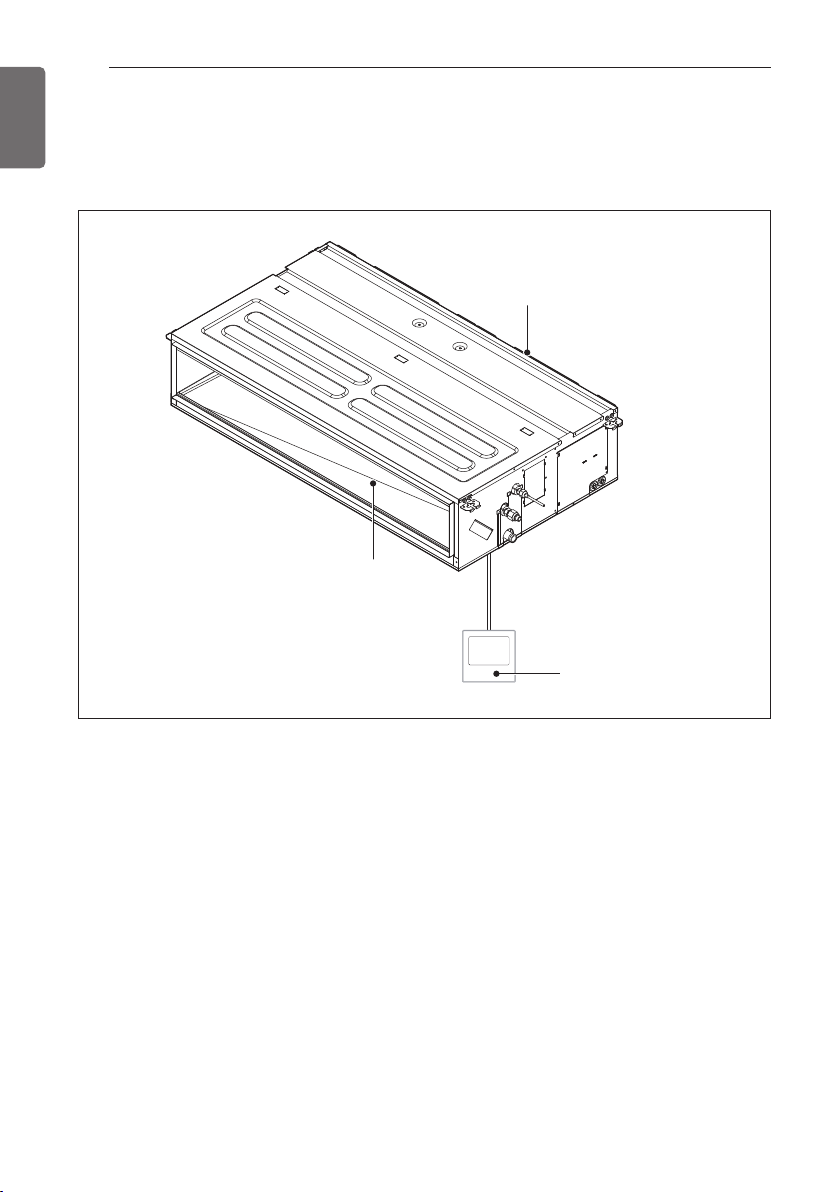
Features
Air inlet vents
Air outlet
vents
Remote Controller
INSTALLATION OF INDOOR
INSTALLATION OF INDOOR
7
ENGLISH
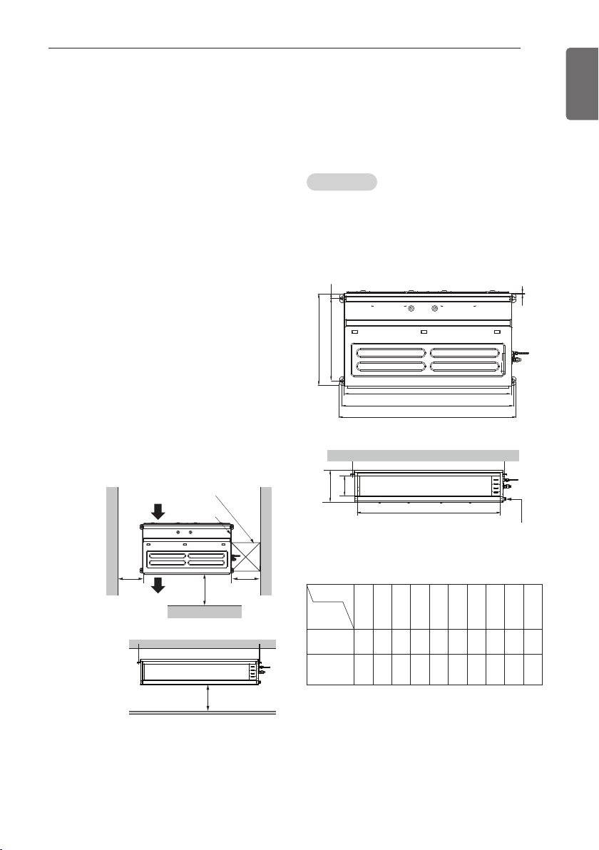
Selection of the best location
- The place shall easily bear a load exceeding
four times the indoor unit’s weight.
- The place shall be able to inspect the unit as
the figure.
- The place where the unit shall be leveled.
- The place shall allow easy water
drainage.(Suitable dimension “H” is
necessary to get a slope to drain as figure.)
- The place shall easily connect with the
outdoor unit.
- The place where the unit is not affected by
an electrical noise.
- The place where air circulation in the room
will be good .
- There should not be any heat source or
steam near the unit
- Confirm the positional relationship between
the unit and suspension bolts.
- Thermal insulator the ceiling opening to clean
the filter or service under the product.
Top view
Unit: mm
Air inlet vents
Inspection hole
600 x 600
Control box
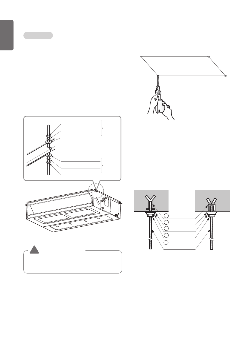
Installation of Unit
Install the unit above the ceiling correctly.
CASE 1
Position of suspension Bolt
- Apply a joint-canvas between the unit and
duct to absorb unnecessary vibration.
- Apply a filter Accessory at air return hole.
E
C
D
J
A
B
I
F
H
Drain hole
G
Front view
Unit: mm
600
Air outlet vents
1000
Front
600
20 or more
Dimension
Capacity
(kBtu/h)
18k/24k/30k
36k/48k/54k
1283.4 1321.6 619.2 691 30 360 15.2 1208 201.4 1250
/60k
(Unit:mm)
A B C D E F G H I J
933.4 971.6 619.2 691 30 270 15.2 858 201.4 900
8
1 Set anchor
Old building New building
2 Plate washer
3 Spring washer
4 Nut
5 Suspension
bolts
ENGLISH
INSTALLATION OF INDOOR
CASE 2
- Install the unit leaning to a drainage hole side
as a figure for easy water drainage.
Position of console Bolt
- A place where the unit will be leveled and
that can support the weight of the unit.
- A place where the unit can withstand its
vibration.
- A place where service can be easily
performed.
M10 Nut
M10 SP. washer
M10 washer
M10 washer
M10 SP. washer
M10 Nut
X 4
X 4
X 4
X 4
X 4
X 4
(Local
supply)
(Local
supply)
- Select and mark the position for fixing bolts.
- Drill the hole for set anchor on the face of
ceiling.
- Insert the set anchor and washer onto the
suspension bolts for locking the suspension
bolts on the ceiling.
- Mount the suspension bolts to the set
anchor firmly.
- Secure the installation plates onto the
suspension bolts (adjust level roughly) using
nuts, washers and spring washers.
CAUTION
!
Tighten the nut and bolt to prevent unit
falling.
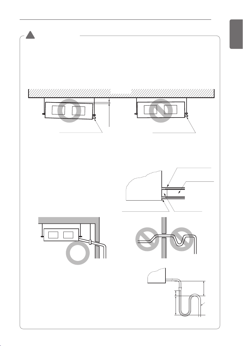
INSTALLATION OF INDOOR
CAUTION
!
• Install declination of the indoor unit is very important for the drain of the duct type air
conditioner.
• Minimum thickness of the insulation for the connecting pipe shall be 5 mm.
Front of view
• The unit must be declined to the drain hose connected when finished installation.
Ceiling
1/100~1/50
CORRECT
Drainage hole
INCORRECT
Drainage hole
Caution for gradient of unit and drain piping
Lay the drain hose with a downward inclination so water will drain out.
9
ENGLISH
•Always lay the drain withdownward
inclination (1/100 to 1/50).
Prevent any upward flow or reverse flow
in any part.
•10 mm or thicker formed thermal insulator
shall always be provided for the drain
pipe.
CORRECT
•Install the P-Trap (or U-Trap) to prevent
a water leakage caused by the blocking
of intake air filter.
Unit
Make sure to be closed.
• Upward routing
not allowed
INCORRECT
Applied U-Trap Dimension
A ≥ 70 mm
B ≥ 2C
C ≥ 2 x SP
SP = External Pressure
(mmAq)
Ex) External Pressure
= 10 mmAq
A ≥ 70 mm
B ≥ 40 mm
C ≥ 20 mm
Thermal insulator
(Local supply)
Drainage pipe
(Local supply)
Drainage hole
C
A
B
U-Trap
10
t
Air filters
ENGLISH
INSTALLATION OF INDOOR
Indoor Unit Drain Piping
- Drain piping must have down-slope (1/50 to
1/100): be sure not to provide up-and-down
slope to prevent reversal flow.
- During drain piping connection, be careful
not to exert extra force on the drain port on
the indoor unit.
- The outside diameter of the drain connection
on the indoor unit is 32 mm.
Piping material: Polyvinyl chloride pipe VP-25
and pipe fittings
- Be sure to execute thermal insulator on the
drain piping.
- Install the drain raising pipes at a right
angle to the indoor unit and no more than
300 mm from the unit.
Pipe clamp
Indoor unit
Maintenance
drain port
Upward
routing
not allowed
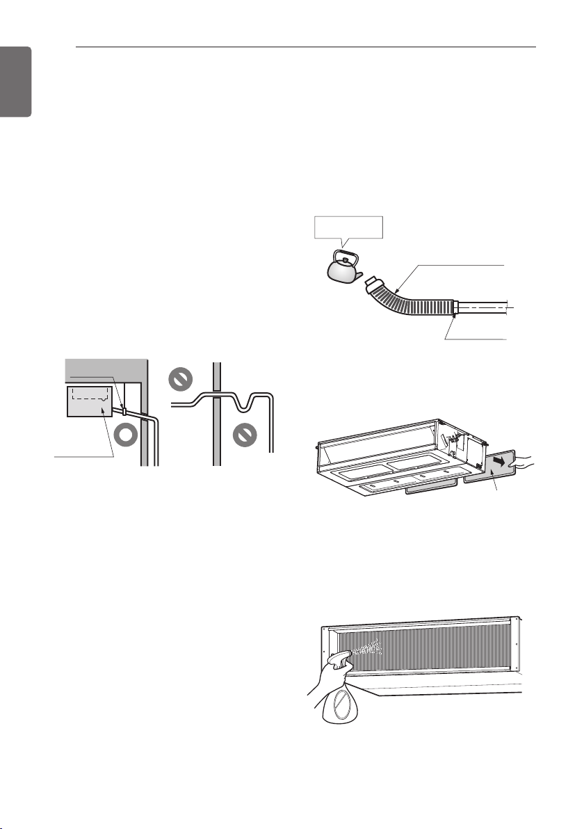
Drain test
- Connect the main drain pipe to the exterior
and leave it provisionally until the test comes
to an end.
- Feed water to the flexible drain hose and
check the piping for leakage.
- When the test is complete, connect the
flexible drain hose to the drain port on the
indoor unit.
Feed water
Flexible drain hose
(accessory)
Main
drain pipe
Glue the join
1 Remove the air filter.
Thermal insulator material: Polyethylene foam
with thickness more than 8 mm.
2 Check the drain.
- Spray one or two glasses of water upon
the evaporator.
- Ensure that water flows drain hose of
indoor unit without any leakage.
Thermal insulator
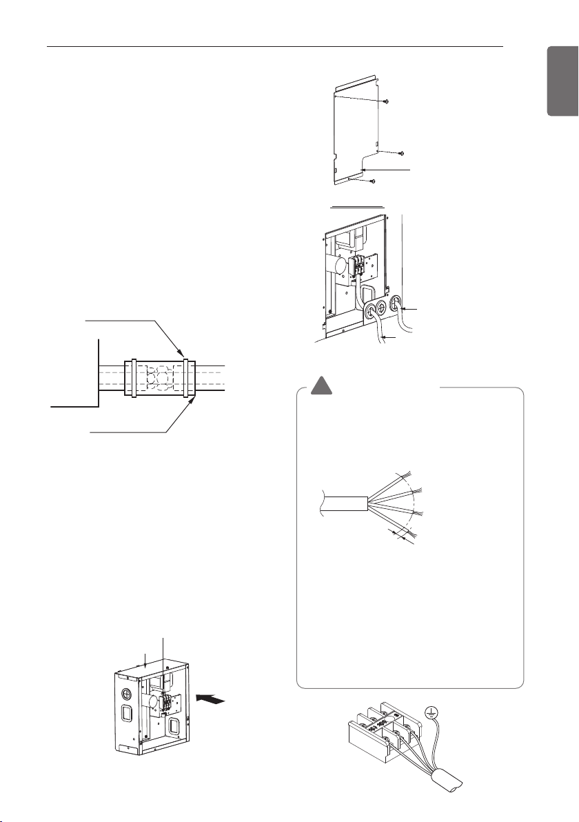
A view
Control box cover
(On which the Electric
Wiring Connection is put)
Remote
controler cable
Connection cable
between the indoor
unit and the outdoor unit
Control terminal board
Control box
A
1 Use the thermal insulator material for the
refrigerant piping which has an excellent
heat-resistance (over 120 °C).
2 If this air conditioner is operated for a long
time in high humid atmosphere (dew point
temperature: more than 23 °C), water
drops are liable to fall. In this case, add
thermal insulator material according to the
following procedure:
- Thermal insulation material to be
prepared... Adiabatic glass wool with
thickness 10 to 20 mm.
- Stick glass wool on all air conditioners
that are located in ceiling atmosphere.
Fastening band
(accessory)
INSTALLATION OF INDOOR
11
ENGLISH
Indoor unit
Wiring Connection
- Open the control box cover and connect the
Remote controller cable and Indoor power
wires.
- Remove the control box cover for electrical
connection between the indoor and outdoor
unit. (Remove screws ①.)
- Use the cord clamper to fix the cable.
Thermal insulator
(accessory)
Refrigerant
piping
CAUTION
!
• The connecting cable connected to the
indoor and outdoor unit should be
complied with the following
specifications (Rubber insulation, type
H05RN-F approved by HAR or SAA).
NORMAL
CROSS-SECTIONAL
GN/YL
•
If the supply cable is damaged, it must be
replaced by a special cable or assembly
available from the manufacturer of its service
agent. When the connection line between the
indoor unit and outdooor unit and outdoor unit
is over 40 m, connect the telecommunication
line and power line separately.
• Pipes and wires should be purchased
separately for installation of the product.
AREA 0.75 mm
20 mm
2
 Loading...