

LG ABNQ36GM3A4 Owner’s Manual
INSTALLATION MANUAL
Ceiling Concealed Duct
ABNQ36GM3A4, ABNQ48GM3A4
AIR
CONDITIONER
Please read this installation manual completely before installing the product.
Installation work must be performed in accordance with the national wiring
standards by authorized personnel only.
Please retain this installation manual for future reference after reading it
thoroughly.
www.lg.com
Copyright © 2014 - 2020 LG Electronics Inc. All Rights Reserved.
MFL67939906
Rev.03_061020
ENGLISH
BAHASA INDONESIA
TIẾNG VIỆT
ภาษาไทย
TIPS FOR SAVING ENERGY
2
ENGLISH
TIPS FOR SAVING ENERGY
Here are some tips that will help you minimize the power consumption when you use the air
conditioner. You can use your air conditioner more efficiently by referring to the instructions
below:
• Do not cool excessively indoors. This may be harmful for your health and may consume more
electricity.
• Block sunlight with blinds or curtains while you are operating the air conditioner.
• Keep doors or windows closed tightly while you are operating the air conditioner.
• Adjust the direction of the air flow vertically or horizontally to circulate indoor air.
• Speed up the fan to cool or warm indoor air quickly, in a short period of time.
• Open windows regularly for ventilation as the indoor air quality may deteriorate if the air
conditioner is used for many hours.
• Clean the air filter once every 2 weeks. Dust and impurities collected in the air filter may block the
air flow or weaken the cooling / dehumidifying functions.
For your records
Staple your receipt to this page in case you need it to prove the date of purchase or for warranty
purposes. Write the model number and the serial number here:
Model number :
Serial number :
You can find them on a label on the side of each unit.
Dealer’s name :
Date of purchase :
SAFETY INSTRUCTIONS
3
SAFETY INSTRUCTIONS
The following safety guidelines are intended to prevent unforeseen risks or damage from unsafe or
incorrect operation of the appliance.
The guidelines are separated into ‘WARNING’ and ‘CAUTION’ as described below.
This symbol is displayed to indicate matters and operations that can cause risk.
!
Read the part with this symbol carefully and follow the instructions in order to avoid risk.
WARNING
!
This indicates that the failure to follow the instructions can cause serious injury or death.
CAUTION
!
This indicates that the failure to follow the instructions can cause the minor injury or damage to
the product.
WARNING
!
• Installation or repairs made by unqualified persons can result in hazards to you and others.
• The information contained in the manual is intended for use by a qualified service technician familiar with
safety procedures and equipped with the proper tools and test instruments.
Installation
• Always perform grounding.
- Otherwise, it may cause electrical shock.
• Don’t use a power cord, a plug or a loose socket which is damaged.
- Otherwise, it may cause a fire or electrical shock.
• For installation of the product, always contact the service center or a professional installation agency.
- Otherwise, it may cause a fire, electrical shock, explosion or injury.
• Securely attach the electrical part cover to the indoor unit and the service panel to the outdoor unit.
- If the electrical part cover of the indoor unit and the service panel of the outdoor unit are not attached
securely, it could result in a fire or electric shock due to dust, water, etc.
• Always install an air leakage breaker and a dedicated switching board.
- No installation may cause a fire and electrical shock.
• Do not keep or use flammable gases or combustibles near the air conditioner.
- Otherwise, it may cause a fire or the failure of product.
• Ensure that an installation frame of the outdoor unit is not damaged due to use for a long time.
- It may cause injury or an accident.
• Do not disassemble or repair the product randomly.
- It will cause a fire or electrical shock.
• Do not install the product at a place that there is concern of falling down.
- Otherwise, it may result in personal injury.
• Use caution when unpacking and installing.
- Sharp edges may cause injury.
• Do not turn on the breaker or power under condition that front panel, cabinet, top cover, control box
cover are removed or opened.
- Otherwise, it may cause fire, electric shock, explosion or death.
Operation
• Do not share the outlet with other appliances.
- It will cause an electric shock or a fire due to heat generation.
• Do not use the damaged power cord.
- Otherwise, it may cause a fire or electrical shock.
ENGLISH
4
ENGLISH
• Do not modify or extend the power cord randomly.
• Take care so that the power cord may not be pulled during operation.
• Unplug the unit if strange sounds, smell, or smoke comes from it.
• Keep the flames away.
• Take the power plug out if necessary, holding the head of the plug and do not touch it with wet hands.
• Do not use the power cord near the heating tools.
• Do not open the suction inlet of the indoor/outdoor unit during operation.
• Do not allow water to run into electrical parts.
• Hold the plug by the head when taking it out.
• Never touch the metal parts of the unit when removing the filter.
• Do not step on the indoor/outdoor unit and do not put anything on it.
• Do not place a heavy object on the power cord.
• When the product is submerged into water, always contact the service center.
• Take care so that children may not step on the outdoor unit.
SAFETY INSTRUCTIONS
- Otherwise, it may cause a fire or electrical shock.
- Otherwise, it may cause a fire or electrical shock.
- Otherwise, it may cause electrical shock or a fire.
- Otherwise, it may cause a fire.
- Otherwise, it may cause a fire or electrical shock.
- Otherwise, it may cause a fire and electrical shock.
- Otherwise, it may electrical shock and failure.
- Otherwise, it may cause the failure of machine or electrical shock.
- It may cause electric shock and damage.
- They are sharp and may cause injury.
- It may cause an injury through dropping of the unit or falling down.
- Otherwise, it may cause a fire or electrical shock.
- Otherwise, it may cause a fire or electrical shock.
- Otherwise, children may be seriously injured due to falling down.
CAUTION
!
Installation
• Install the drain hose to ensure that drain can be securely done.
- Otherwise, it may cause water leakage.
• Install the product so that the noise or hot wind from the outdoor unit may not cause any damage to the
neighbors.
- Otherwise, it may cause dispute with the neighbors.
• Always inspect gas leakage after the installation and repair of product.
- Otherwise, it may cause the failure of product.
• Keep level parallel in installing the product.
- Otherwise, it may cause vibration or water leakage.
• Do not install the unit in potentially explosive atmospheres.
Operation
• Avoid excessive cooling and perform ventilation sometimes.
- Otherwise, it may do harm to your health.
• Use a soft cloth to clean. Do not use wax, thinner, or a strong detergent.
- The appearance of the air conditioner may deteriorate, change color, or develop surface flaws.
• Do not use an appliance for special purposes such as preserving animals vegetables, precision machine,
or art articles.
- Otherwise, it may damage your properties.
• Do not place obstacles around the flow inlet or outlet.
- Otherwise, it may cause the failure of appliance or an accident.
• Means for disconnection must be incorporated in the fixed wiring in accordance with the wiring rules.
TABLE OF CONTENTS
2 TIPS FOR SAVING ENERGY
3 SAFETY INSTRUCTIONS
6 INTRODUCTION
6 Features
7 INSTALLATION OF INDOOR
7 Selection of the best location
7 Ceiling dimension and hanging bolt location
10 Wiring Connection
11 Indoor Unit Drain Piping
11 Drain test
12 Heat insulation
13 REMOTE CONTROLLER INSTALLATION
14 Group Control
16 OPTIONAL OPERATION
16 Installer Setting - Test Run Mode
17 Installer Setting - Setting Address of Central Control
18 Installer Setting - Thermistor
19 Installer Setting - Remote Controller Master/Slave Setup
20 Installer Setting - Celsius / Fahrenheit Switching
21 Installer Setting - E.S.P.
22 Installer Setting - Static Pressure Step Setting
TABLE OF CONTENTS
5
ENGLISH
26 DIP SWITCH SETTING
INTRODUCTION
6
ENGLISH
INTRODUCTION
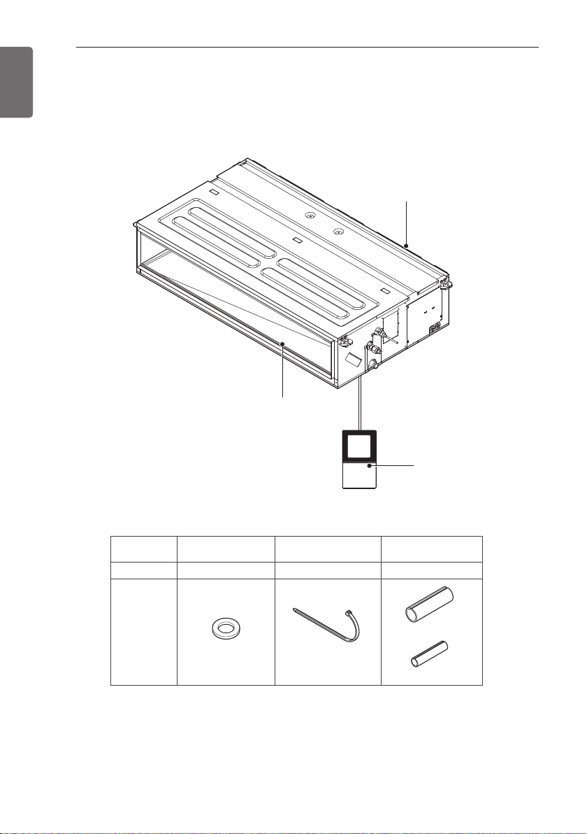
Features
Air inlet vents
Air outlet
vents
Name
Quantity
Shape
• Screws for fixing panels are attached to decoration panel.
Washer for
hanging bracket
8 EA
Clamp
(Tie Wrap)
4 EA
Remote
Controller
Insulation for
fitting
1 set
for gas pipe
for liquid pipe
C
E
G
D
F
I
A
J
B
H
Drain hole
INSTALLATION OF INDOOR
INSTALLATION OF INDOOR
7
ENGLISH
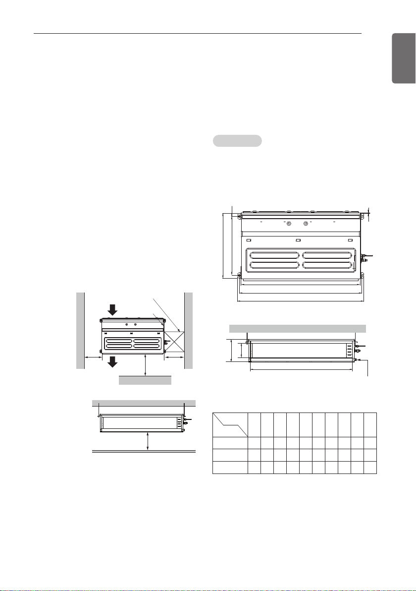
Selection of the best location
Install the air conditioner in the location that
satisfies the following conditions.
- The place shall easily bear a load exceeding
four times the indoor unit’s weight.
- The place shall be able to inspect the unit as
the figure.
- The place where the unit shall be leveled.
- The place shall easily connect with the
outdoor unit.
- The place where the unit is not affected by
an electrical noise.
- The place where air circulation in the room
will be good .
- There should not be any heat source or
steam near the unit
Top view
Unit: mm
Air inlet vents
600
Air outlet vents
Inspection hole
600 x 600
Control box
1 000
Front
600
Ceiling dimension and hanging
bolt location
Install the unit above the ceiling correctly.
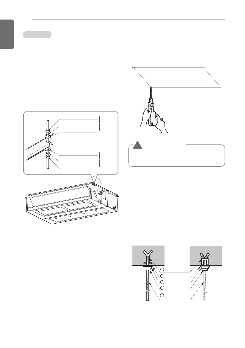
CASE 1
Position of suspension Bolt
- Apply a joint-canvas between the unit and
duct to absorb unnecessary vibration.
- Apply a filter Accessory at air return hole.
Front view
Unit: mm
Confirm the positional relationship between
the unit and suspension bolts.
- Installation the ceiling opening to clean the
filter or service under the product.
20 or more
Dimension
Chassis
M1
M2
M3
(Unit:mm)
A B C D E F G H I J
933.4 971.6 619.2 700 30 270 15.2 858 201.4 900
1 283.4 1 321.6 619.2 700 30 270 15.2 1 208 201.4 1 250
1 283.4 1 321.6 619.2 700 30 360 15.2 1 208 291.4 1 250
8
M10 Nut
M10 SP. washer
M10 washer
X 4
X 4
(Local
supply)
X 4
M10 Nut
M10 SP. washer
M10 washer
X 4
X 4
(Local
supply)
X 4
1 Set anchor
Old building New building
2 Plate washer
3 Spring washer
4 Nut
5 Suspension
bolts
ENGLISH
INSTALLATION OF INDOOR
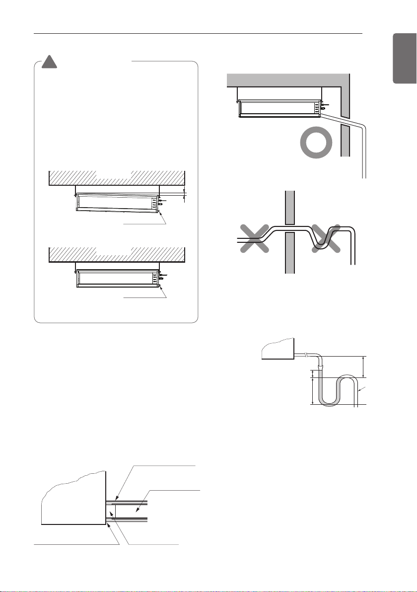
CASE 2
- Install the unit leaning to a drainage hole side
as a figure for easy water drainage.
Position of console Bolt
- A place where the unit will be leveled and
that can support the weight of the unit.
- A place where the unit can withstand its
vibration.
- A place where service can be easily
performed.
Select and mark the position for
fixing bolts
- Drill the hole for set anchor on the face of
ceiling.
CAUTION
!
Tighten the nut and bolt to prevent unit
falling.
- Insert the set anchor and washer onto the
suspension bolts for locking the suspension
bolts on the ceiling.
- Mount the suspension bolts to the set
anchor firmly.
- Secure the installation plates onto the
suspension bolts (adjust level roughly) using
nuts, washers and spring washers.
INSTALLATION OF INDOOR
Ceiling
Ceiling
1~3 mm
Drain hole
Drain pump unuse
Drain pump use
Drain hole
Drainage holeMake sure to be closed.
Unit
Drainage pipe
(Local supply)
Thermal insulator
(Local supply)
INCORRECT
CORRECT
U-Trap
B
C
A ≥ 70 mm
B ≥ 2C
C ≥ 2 x SP
SP = External Pressure
(mmAq)
Ex) External Pressure
= 10 mmAq
A ≥ 70 mm
B ≥ 40 mm
C ≥ 20 mm
A
9
ENGLISH
CAUTION
!
• Install declination of the indoor unit is
very important for the drain of the duct
type air conditioner.
• Minimum thickness of the insulation for
the connecting pipe shall be 5 mm.
• The unit must be horizontal or declined
to the drain hose connected when
finished installation.
- Upward routing not allowed
- Install the P-Trap (or U-Trap) to prevent a
water leakage caused by the blocking of
intake air filter.
Caution for gradient of unit and
drain piping
Lay the drain hose with a downward
inclination so water will drain out.
- Always lay the drain with downward
inclination (1/50 to 1/100). Prevent any
upward flow or reverse flow in any part.
- 5mm or thicker formed thermal insulator
shall always be provided for the drain pipe.
 Loading...