

LG ATNH606DLFC, ATNH186ELFC, AVNH126ELAC, AVNH186BLAC, AVNH246BLAC Service Manual
...
LG
Synchro
Air Conditioner
SERVICE MANUAL
LG
CAUTION
website http://www.lgservice.com
e-mail http://www.lgeservice.com/techsup.html
• BEFORE SERVICING THE UNIT, READ THE SAFETY
PRECAUTIONS IN THIS MANUAL.
• ONLY FOR AUTHORIZED SERVICE PERSONNEL.

2 Synchro Air Conditioner
Synchro Air Conditioner Service Manual
TABLE OF CONTENTS
Model Number Nomenclature......................................................................3
Safety Precautions .......................................................................................4
Model Names...............................................................................................11
External Appearance..................................................................................12
Dimensions .................................................................................................13
Product Specifications...............................................................................21
Combination table ......................................................................................25
Installation...................................................................................................26
Operation ....................................................................................................61
Control Devices and Function...................................................................76
Schematic Diagram ....................................................................................89
Piping Diagrams .......................................................................................100
Troubleshooting Guide.............................................................................105
(3-way) Valve ............................................................................................126
Function ....................................................................................................130
Exploded View & Replacement Parts List..............................................147
Service Manual 3
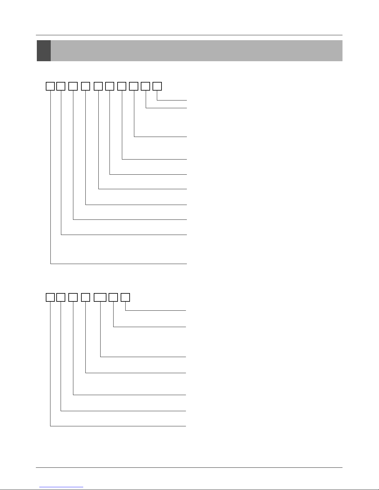
Model Number Nomenclature
Model Number Nomenclature
Indoor Unit
Outdoor Unit
A T N H 18 6 E L F B
Serial Number
Function
A : Basic
E : E/Grille
F : Plasma + Elevation grille
Panel type
Cassette L : Basic panel, W : Wooden panel
Duct : L
Chassis type
Cassette : E/F/D, Convertible : E/B, Duct : H/G/R
Electrical Rating
6 : 1Ø 220-240V ,50Hz
Nominal Cooling Capacity in Btu/h
Ex)18,000Btu/h '18', 24,000Btu/h '24'
Model Type
H : Heat Pump
Unit Type
N : Indoor Unit U : Outdoor Unit
Indoor Unit Type
T : Ceiling Cassette
V : Ceiling&Floor(Convertible)
B : Ceiling Concealed Duct
Refrigerent Type
A : R410A, L : R22
A U U H 100 8 0
Air Discharge Type
0 : Top discharge, A : Side discharge
Electrical Rating(Volt/Hertz/Phase)
1 : 115 / 60 / 1 2 : 220 / 60 / 1
3 : 208-230 / 60 / 1 5 : 200-220 / 50 / 1
6 : 220-240 / 50 / 1 8 : 380-415 / 50 / 3
Nominal Cooling Capacity in Btu/h
Ex)72,000Btu/h '72', 100,000Btu/h '100'
Model Type
W : DC Inverter Heat Pump(MPS Inverter)
H : Conventional Heat Pump(MPS Variable)
Unit Type
N : Indoor Unit, U : Outdoor Unit
Indoor Unit Type
2/3/4 : Multi Room, U : Universal, B : Duct, T : Cassette
Refrigerent Type
A : R410A, L : R22
4 Synchro Air Conditioner
Safety Precautions
Safety Precautions
To prevent injury to the user or other people and property damage, the following instructions must
be followed.
■ Incorrect operation due to ignoring instruction will cause harm or damage. The seriousness is
classified by the following indications.
■ Meanings of symbols used in this manual are as shown below.
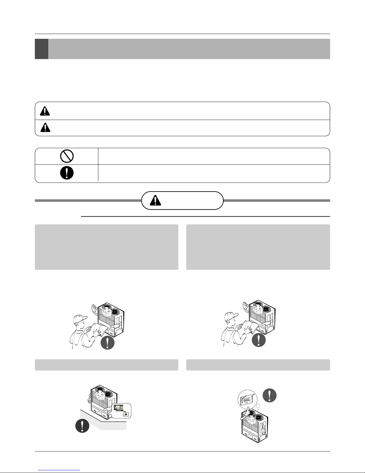
WARNING
CAUTION
This symbol indicates the possibility of death or serious injury.
This symbol indicates the possibility of injury or damage to properties only.
Be sure not to do.
Be sure to follow the instruction.
WARNING
■ Installation
Have all electric work done by a licensed
electrician according to "Electric Facility
Engineering Standard" and "Interior Wire
Regulations" and the instructions given in
this manual and always use a special circuit.
• If the power source capacity is inadequate or
electric work is performed improperly, electric
shock or fire may result.
Ask the dealer or an authorized technician to
install the air conditioner.
• Improper installation by the user may result in
water leakage, electric shock, or fire.
Always ground the product.
• There is risk of fire or electric shock.
Always intstall a dedicated circuit and breaker.
• Improper wiring or installation may cause fire or
electric shock.
Service Manual 5
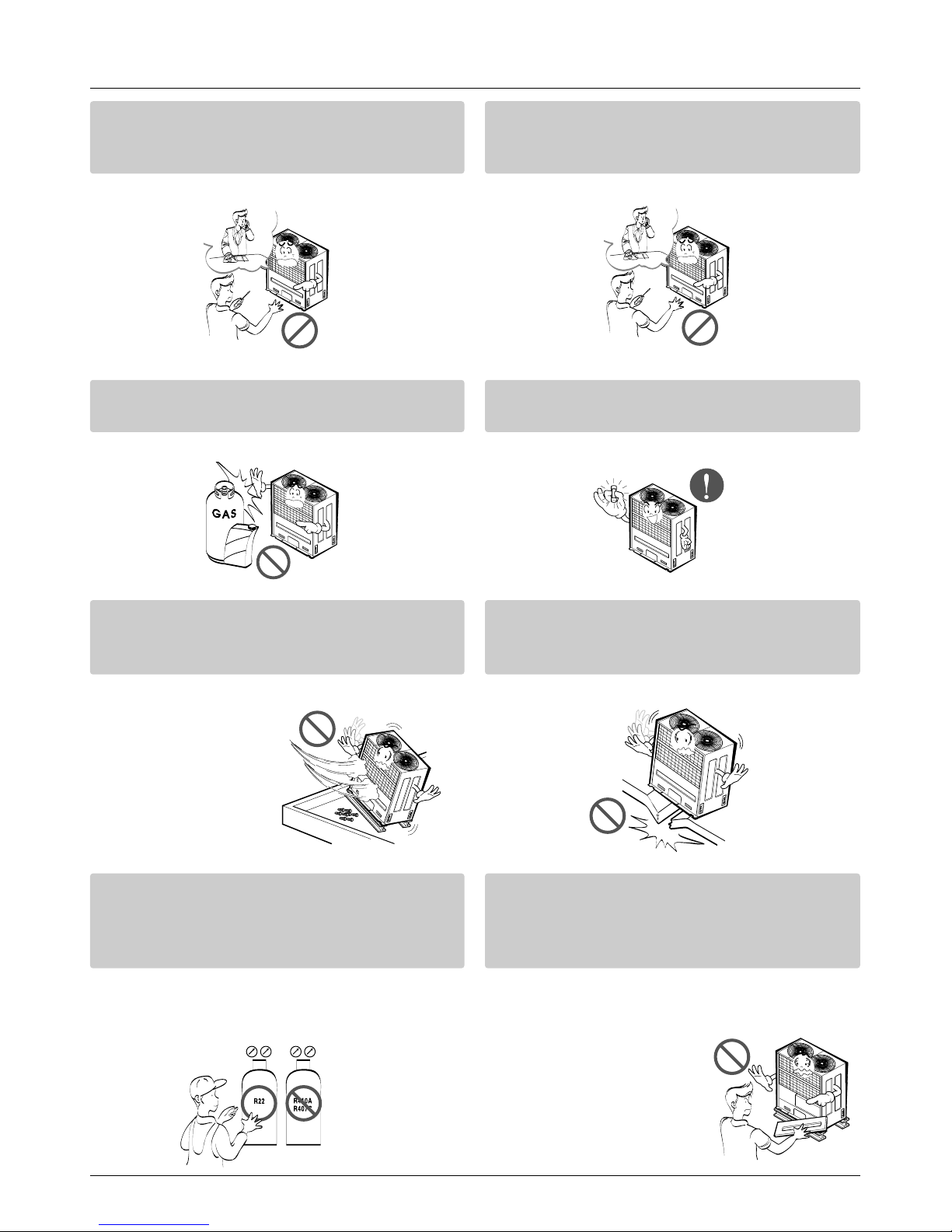
Safety Precautions
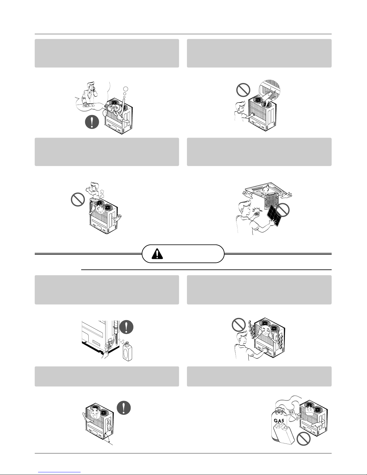
For re-installation of the installed product,
always contact a dealer or an Authorized
Service Center.
• There is risk of fire, electric shock, explosion, or
injury.
Do not install, remove, or re-install the unit
by yourself (customer).
• There is risk of fire, electric shock, explosion, or
injury.
Do not store or use flammable gas or
combustibles near the air conditioner.
• There is risk of fire or failure of product.
Use the correctly rated breaker or fuse.
• There is risk of fire or electric shock.
Prepare for strong wind or earthquake and
install the unit at the specified place.
• Improper installation may cause the unit to topple and result in injury.
Do not install the product on a defective
installation stand.
• It may cause injury, accident, or damage to the
product.
When installing and moving the air conditioner to another site, do not charge it with a
different refrigerant from the refrigerant
specified on the unit.
• If a different refrigerant or air is mixed with the
original refrigerant, the refrigerant cycle may
malfunction and the unit may be damaged.
Do not reconstruct to change the settings of
the protection devices.
• If the pressure switch, thermal switch, or other
protection device is shorted and operated
forcibly, or parts other than
those specified by LGE are
used, fire or explosion may
result.
Gasolin
6 Synchro Air Conditioner
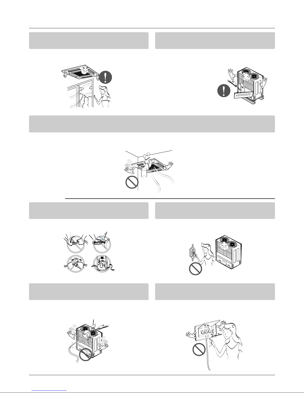
Safety Precautions
Ventilate before operating air conditioner
when gas leaked out.
• It may cause explosion, fire, and burn.
Securely install the cover of control box and
the panel.
• If the cover and panel are not installed securely,
dust or water may enter the outdoor unit and fire
or electric shock may result.
If the air conditioner is installed in a small room, measures must be taken to prevent the
refrigerant concentration from exceeding the safety limit when the refrigerant leaks.
• Consult the dealer regarding the appropriate measures to prevent the safety limit from being exceeded. Should the refrigerant leak and cause the safety limit to be exceeded, harzards due to lack of oxygen in the room could result.
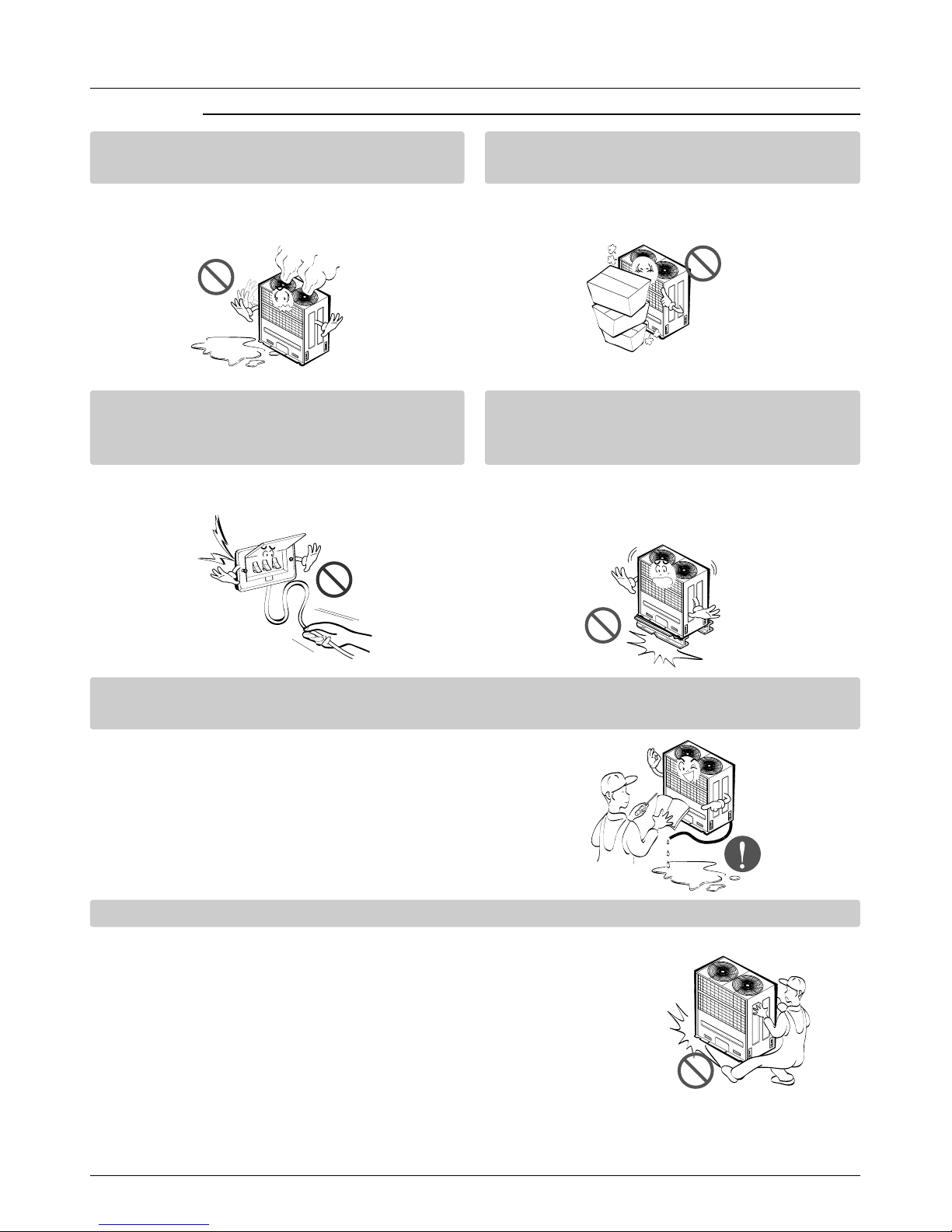
■ Operation
Do not damage or use an unspecified power
cord.
• There is risk of fire, electric shock, explosion, or
injury.
Use a dedicated outlet for this appliance.
• There is risk of fire or electrical shock.
Be cautious that water could not enter the
product.
• There is risk of fire, electric shock, or product
damage.
Do not touch the power switch with wet
hands.
• There is risk of fire, electric shock, explosion, or
injury.
Service Manual 7
Safety Precautions
When the product is soaked (flooded or
submerged), contact an Authorized Service
Center.
• There is risk of fire or electric shock.
Be cautious not to touch the sharp edges
when installing.
• It may cause injury.
Take care to ensure that nobody could step
on or fall onto the outdoor unit.
• This could result in personal injury and product
damage.
Do not open the inlet grill of the product during operation. (Do not touch the electrostatic
filter, if the unit is so equipped.)
• There is risk of physical injury, electric shock, or
product failure.
CAUTION
■ Installation
Always check for gas (refrigerant) leakage
after installation or repair of product.
• Low refrigerant levels may cause failure of
product.
Do not install the product where the noise or
hot air from the outdoor unit could damage
the neighborhoods.
• It may cause a problem for your neighbors.
Keep level even when installing the product.
• To avoid vibration or water leakage.
Do not install the unit where combustible gas
may leak.
• If the gas leaks and accumulates around the
unit, an explosion may result.
90˚
Gasolin

8 Synchro Air Conditioner
Safety Precautions
Use power cables of sufficient current
carrying capacity and rating.
• Cables that are too small may leak, generate
heat, and cause a fire.
Do not use the product for special purposes,
such as preserving foods, works of art, etc. It
is a consumer air conditioner, not a precision
refrigeration system.
• There is risk of damage or loss of property.
Keep the unit away from children. The heat
exchanger is very sharp.
• It can cause the injury, such as cutting the finger.
Also the damaged fin may result in degradation
of capacity.
When installting the unit in a hospital, communication station, or similar place, provide
sufficient protection against noise.
•
The inverter equipment, private power generator,
high-frequency medical equipment, or radio communication equipment may cause the air conditioner to operate erroneously, or fail to operate. On the
other hand, the air conditioner may affect such
equipment by creating noise that disturbs medical
treatment or image broadcasting.
Do not install the product where it is exposed to sea wind (salt spray) directly.
• It may cause corrosion on the product. Corrosion, particularly on the condenser and evaporator fins,
could cause product malfunction or inefficient operation.
Service Manual 9
Safety Precautions
■ Operation
Do not use the air conditioner in special
environments.
• Oil, steam, sulfuric smoke, etc. can significantly
reduce the performance of the air conditioner or
damage its parts.
Do not block the inlet or outlet.
• It may cause failure of appliance or accident.
Make the connections securely so that the
outside force of the cablemay not be applied
to the terminals.
• Inadequate connection and fastening may generate heat and cause a fire.
Be sure the installation area does not deteriorate with age.
• If the base collapses, the air conditioner could
fall with it, causing property damage, product
failure, or personal injury.
Install and insulate the drain hose to ensure that water is drained away properly based on the
installation manual.
• A bad connection may cause water leakage.
Be very careful about product transportation.
• Only one person should not carry the product if it weighs more
than 20 kg.
• Some products use PP bands for packaging. Do not use any PP
bands for a means of transportation. It is dangerous.
• Do not touch the heat exchanger fins. Doing so may cut your fingers.
• When transporting the Outdoor Unit, suspending it at the specified
positions on the unit base. Also support the Outdoor Unit at four
points so that it cannot slip sideways.
10 Synchro Air Conditioner
Safety Precautions
Safely dispose of the packing materials.
•
Packing materials, such as nails and other metal or
wooden parts, may cause stabs or other injuries.
•
Tear apart and throw away plastic packaging bags
so that children may not play with them. If children
play with a plastic bag which was
not torn apart, they face the
risk of suffocation.
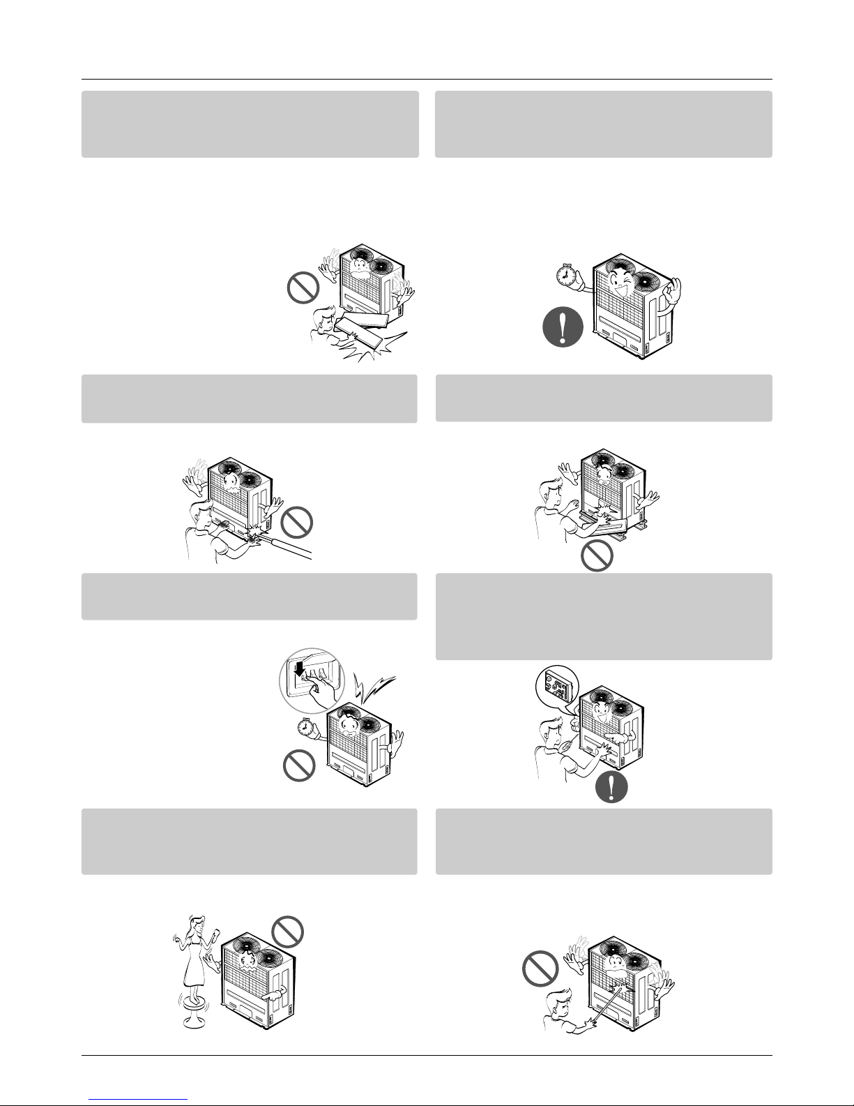
Turn on the power at least 12 hours before
starting operation.(In case of outdoor
temperature 5°C below)
• Starting operation immediately after turning on
the main power switch can result in severe
damage to internal parts. Keep the power switch
turned on during the operational season.
Do not touch any of the refrigerant piping
during and after operation.
• It can cause a burn or frostbite.
Do not operate the air conditioner with the
panels or guards removed.
• Rotating, hot, or high-voltage parts can cause
injuries.
Do not directly turn off the main power
switch after stopping operation.
• Wait at least 5 minutes before turning off the
main power switch.
Otherwise it may result in
water leakage or other
problems.
Auto-addressing should be done in condition of
connecting the power of all indoor and outdoour
units. Auto-addressing should also be done in
case of changing the Indoor Unit board(PCB).
Use a firm stool or ladder when cleaning or
maintaining the air conditioner.
• Be careful and avoid personal injury.
Do not insert hands or other objects through
the air inlet or outlet while the air conditioner
is plugged in.
• There are sharp and moving parts that could
cause personal injury.
Service Manual 11
Model Names
Model Names
Indoor Unit
Outdoor Unit
Branch Kit
TE
Ceiling Cassette 4-Way TF
TD
Ceiling & Floor(Convertible)
VE
VB
BH
Ceiling Concealed Duct BG
BR
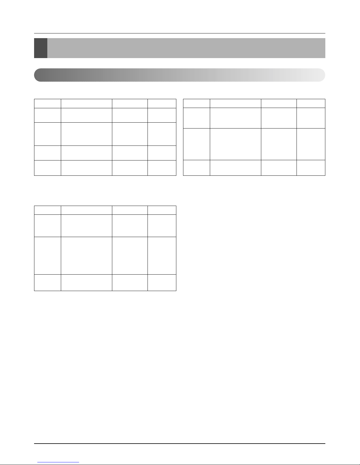
Model Name
Nominal Capacity[Btu/h(Kw)]
Chassis
Name
Type
12,000
(3.5)
18,000
(5.3)
24,000
(7.0)
30,000
(8.8)
36,000
(10.6)
48,000
(14.1)
60,000
(17.6)
ATNH126ELFC ATNH186ELFC - - - -
- - ATNH246FLFC ATNH306FLFC - -
- - - - ATNH366DLFC ATNH486DLFC ATNH606DLFC
AVNH126ELAC - - - - -
- AVNH186BLAC AVNH246BLAC AVNH306BLAC - -
- ABNH186HLAC ABNH246HLAC - - -
- - - ABNH306GLAC ABNH366GLAC -
- - - - - ABNH486RLAC ABNH606RLAC
Indoor Unit
UH AUUH488C - - -
MPS Variable UY - - AUUH 728C -
UW - - - AUUH1008C
Model Name
Nominal Capacity[Btu/h(Kw)]
Type
Chassis
Name
48,000
(14.0)
60,000
(17.6)
72,000
(21.1)
100,000
(29.0)
Outdoor Unit
Name of accessory
Model No. Indoor classification Capacity Ratio(%) Remark
PMUB11A
"Synchro" Duo
50:50(1:1)
PMUB23A 40:60(2:3) Unbalance type
Branch Kit
PMUB111A 33:33:33(1:1:1)
PMUB112A "Synchro" Trio 25:25:50(1:1:2) Unbalance type
PMUB122A 20:40:40(1:2:2) Unbalance type
PMUB1111A "Synchro" Quartet 25:25:25:25(1:1:1:1)
12 Synchro Air Conditioner
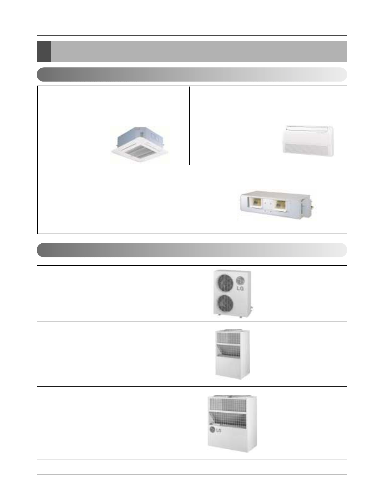
External Appearance
External Appearance
Indoor Unit
Outdoor Unit
Ceiling Cassette-4Way Ceiling & Floor(Convertible)
Ceiling Concealed Duct
ATNH126ELFC / ATNH186ELFC
ATNH246FLFC / ATNH306FLFC
ATNH366DLFC / ATNH486DLFC
ATNH606DLFC
AVNH126ELAC / AVNH186BLAC
AVNH246BLAC / AVNH306BLAC
ABNH186HLAC / ABNH246BHLAC
ABNH306GLAC / ABNH366BGLAC
ABNH486RLAC / ABNH606RLAC
AUUH728C
AUUH488C
AUUH1008C
Service Manual 13
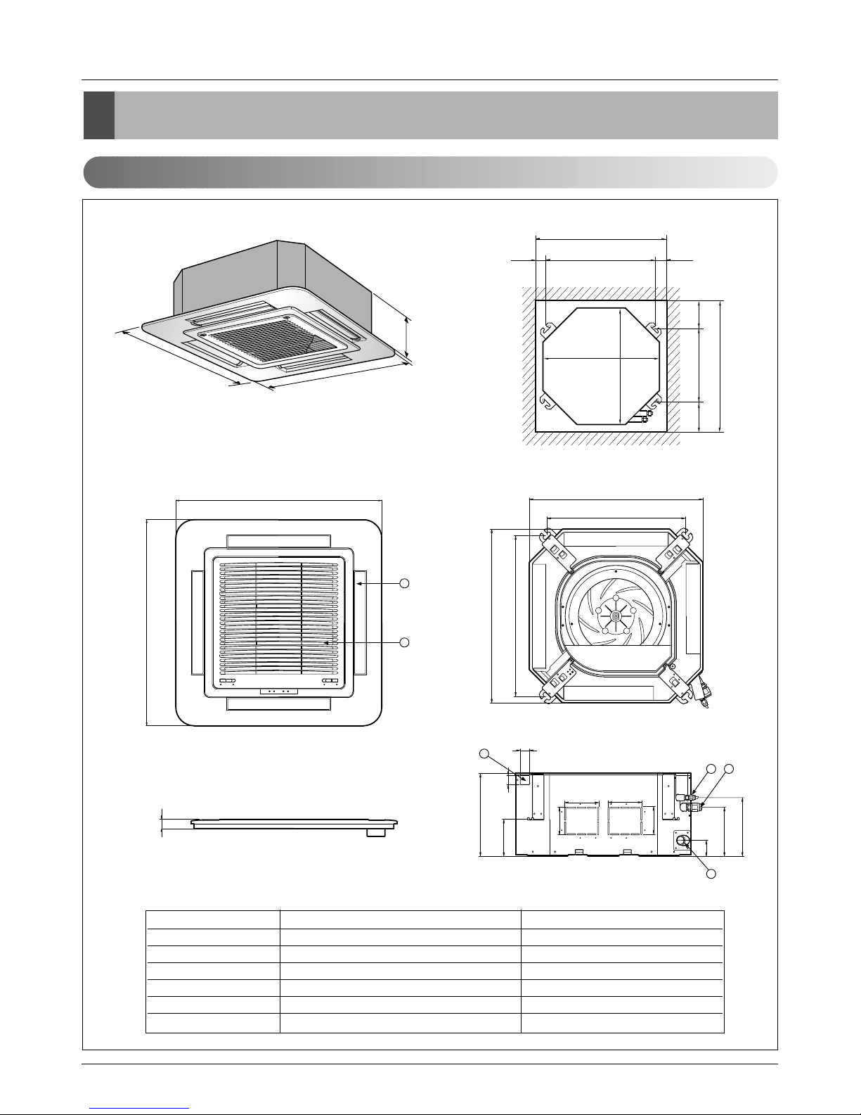
Dimensions
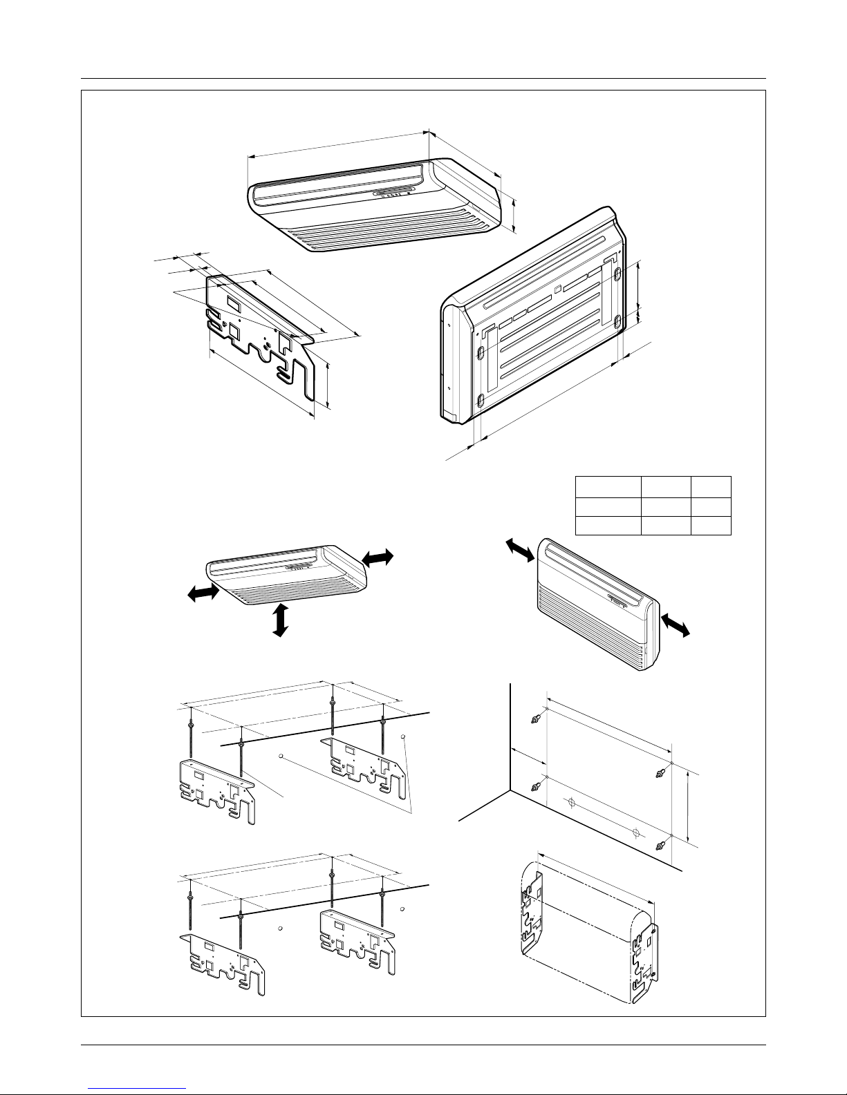
Dimensions
Indoor Unit
CLOSE OPEN OPEN CLOSE
269
670
30
570
269
190.5
160
52
90
90
120.4
30
521
670
570
450
40
110 110
670
670
4
132
5
6
Unit:mm
570 Unit size
570 Unit size
450 (Hanging bolt)
7575
600 (Ceiling opening)
600 (Ceiling opening)
521(Hanging bolt)
39.5
39.5
1. Cassette Type - TE(12K/18K)
(unit : mm)
Number Name Descripition
1 Liquid pipe connection ø6.35 flare
2 Gas pipe connection
12k: ø9.52, 18k: ø12.7 flare
3 Drain pipe connection
4 Power supply connection
5 Air discharge grill
6 Air suction grill
14 Synchro Air Conditioner
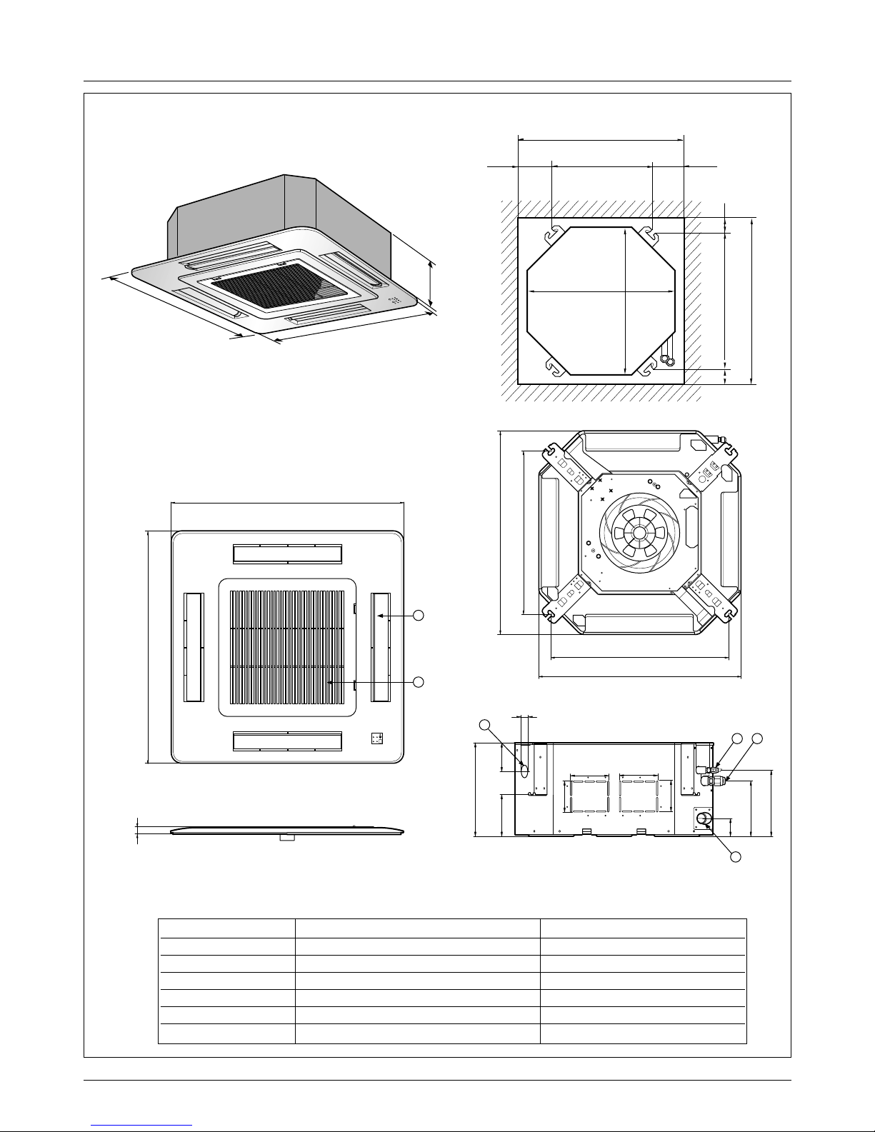
Dimensions
2. Cassette Type - TF (24K/30K)
292
850
850
850
850
744
658
572
744
292
212
150
54
90
90
192 117
70
110 110
4
132
5
6
Unit:mm
744 Unit size
744 Unit size
658 (Hanging bolt)
6666
790 (Ceiling opening)
790 (Ceiling opening)
572(Hanging bolt)
109
109
30
(unit : mm)
Number Name Descripition
1 Liquid pipe connection ø6.35 flare
2 Gas pipe connection
24K: ø12.7, 30K: ø15.88 flare
3 Drain pipe connection
4 Power supply connection
5 Air discharge grill
6 Air suction grill
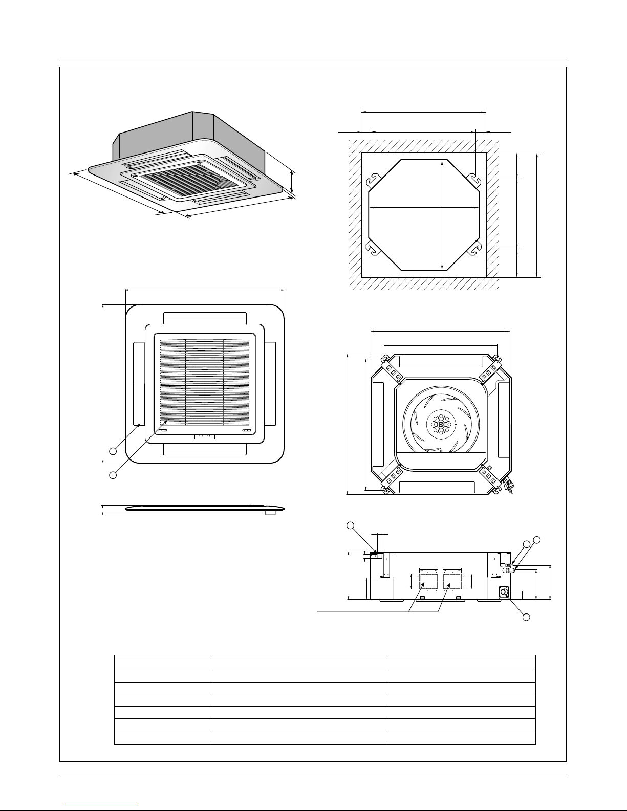
Service Manual 15
Dimensions
288
950
950
950
950
290
210.5
180
52
140
40
110
30
90
90
110
55
840
785
840
678
Fresh Air Inlet
Unit:mm
840 Unit size
840 Unit size
672 (Hanging bolt)
101.5101.5
875 (Ceiling opening)
875 (Ceiling opening)
785 (Hanging bolt)
45
45
4
5
6
1
3
2
(unit : mm)
Number Name Descripition
1 Liquid pipe connection
36K: ø6.35, 48K/60K: ø9.52 flare
2 Gas pipe connection
36K: ø15.88, 48K/60K: ø19.05 flare
3 Drain pipe connection
4 Power supply connection
5 Air discharge grill
6 Air suction grill
3. Cassette Type - TD(36K/48K/60K)
16 Synchro Air Conditioner
Dimensions
Ø 12.7Ø 6.3518k, 24k
Ø 15.88Ø 6.3530k
GasLiquidModel
1. Pipe Specification(mm)
Note:
1200
205
615
R
More than
20cm
More than eye-level
More than
20cm
R
(Ceiling installation)
R
More than
20cm
More than
20cm
(Floor/Wall installation)
(Rear Side)
(Unit: mm)
1076
Suspension bolt
(W3/8 or M10)
Center-line for the
piping hole
265
1236
265
1076
more than
260
265
1236
392
265
468
63
Ø10 Stud Bolt hole
38
175
(Installation Plate)
250
128
36
36
1
076
4. Ceiling & Floor(Convertible) - VB(18K/24K), VE(12K)
Service Manual 17
Dimensions
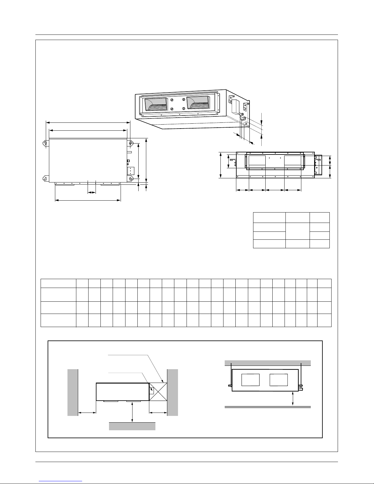
Top view
(unit: mm)
Front view
600600
Front
Inspection hole
※Suitable dimension "H" is necessary
to get a slope to drain as figure.
(600X600)
Control box
1000
H
l
i
h
j
k
A
H
CD
EF
B
(G)
ab c d
K
J
fe
Ø 12.7
Ø 15.88
Ø 6.35
Ø 9.52
18, 24k
30, 36
Ø 19.05
48, 60k
k
GasLiquidModel
1. Pipe Specification(mm)
Note:
C D E F (G) H J K a b c d e f h i j k l
355 45.5 450 30 87 750 163 260 61.5 243 212.3 243 110 130 52 66 81 30 158.5
355 45.5 450 30 87 830 186 298 229.5 243 232 243 116 160 53 59 81 19 158.5
477 56 590 30 120 1006 294 380 215 279 241 279 185 168 51 98 83 17 172
Capacity A B
932 882
1232 1182
1282 1230
ABNH186HLAC
ABNH246HLAC
ABNH306GLAC
ABNH366GLAC
ABNH486RLAC
ABNH606RLAC
(Unit: mm)
5. Ceiling Concealed Duct - BH(18K/24K), BG(30K/36K), BR(48K/60K)
18 Synchro Air Conditioner
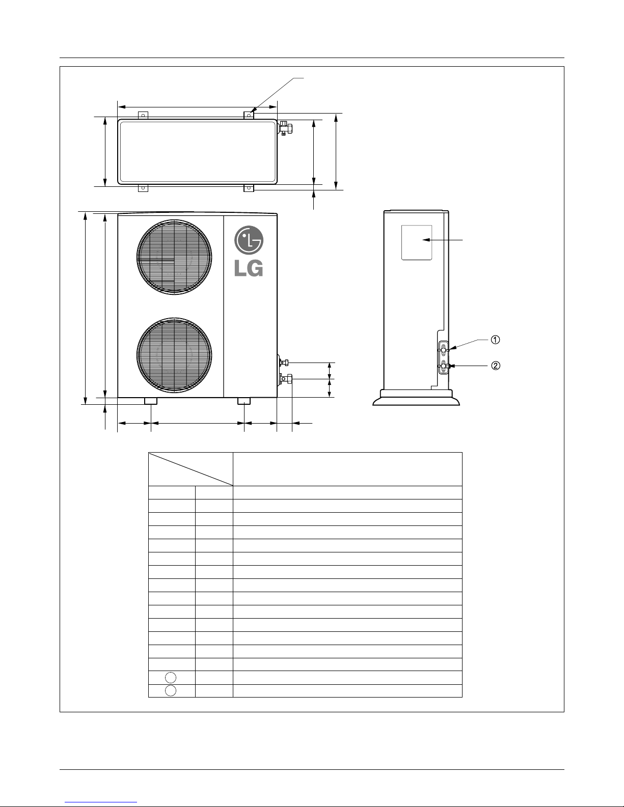
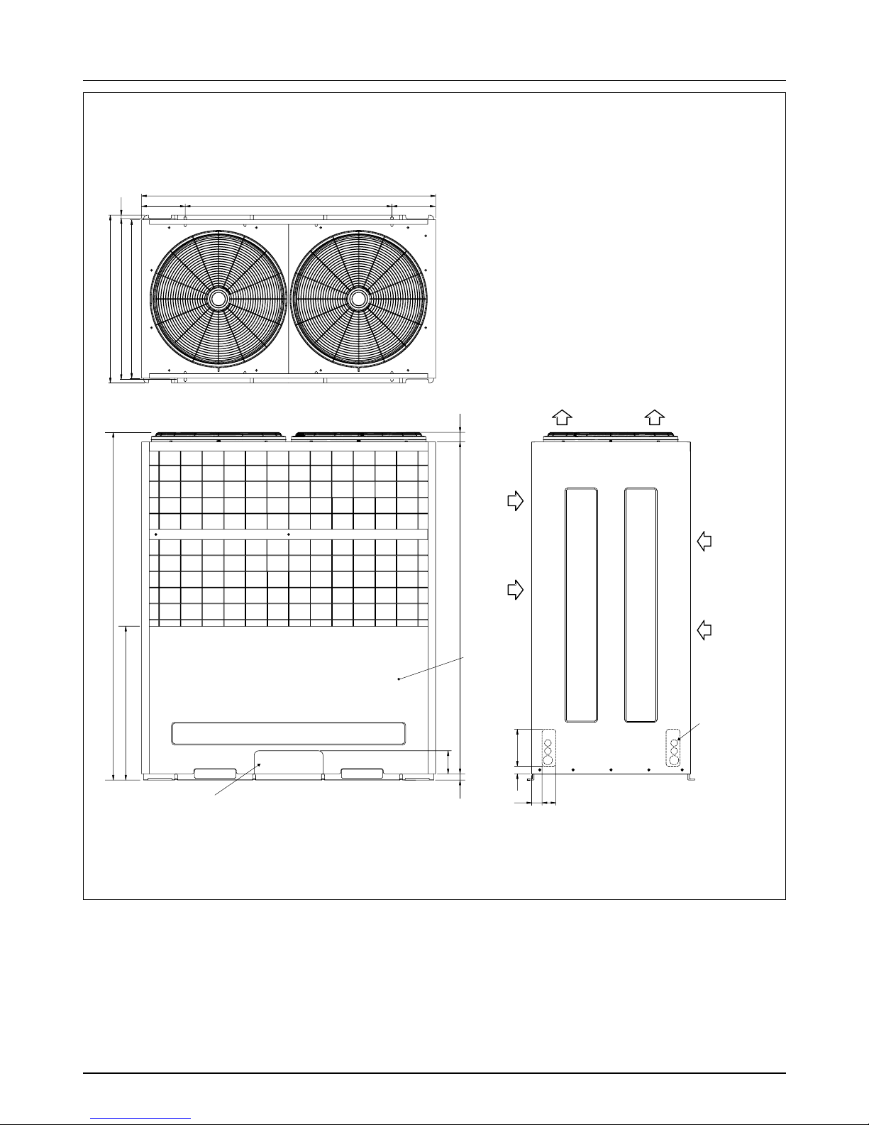
Dimensions
AUUH488C
L6L7 L8 L9
L4
H
L11
L10
L5
W
D
L1
L2
L3
Gas side
3-way valve
Control cover
Liquid side
3-way valve
4-hole for anchor bolts
Wmm 900
Hmm 1
,165
Dmm
370
L1 mm
460
L2 mm
45
L3 mm
410
L4 mm
1,135
L5 mm
30
L6 mm
550
L7 mm
175
L8 mm
175
L9 mm
112
L10 mm
120
L11
1
2
mm
83
mm Ø9.52
mm Ø19.05
AUUH488C
Model
Dimensions
Service Manual 19
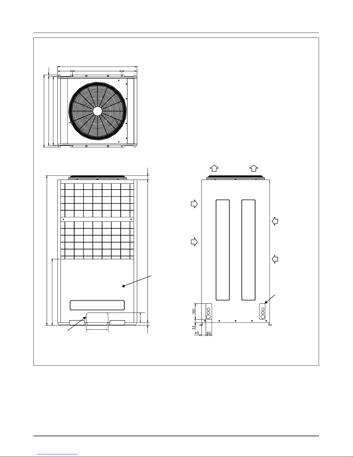
Dimensions
AUUH728C
Air
inlet
Air
inlet
Air outlet
Service Panel
(Unit : mm)
Knockout hole
(For the control wiring,
the power supply,
refrigerant connecting
pipe)
Knockout hole
(For the control wiring, the power supply,
refrigerant connecting pipe)
153
15
690
40
144428
100
220
1512
670
730
153
806
500(bolt hole)
700(bolt hole)
20 Synchro Air Conditioner
Dimensions
45
33 160
60
15
190 900(bolt hole)
1280
190
700(bolt hole)
730
690
670
1555
63 1444
48
100
Air
inlet
Air
inlet
Air outlet
Service Panel
Knockout hole
Knockout hole
(For the control wiring, the power supply,
refrigerant connecting pipe)
(For the control wiring,
the power supply,
refrigerant connecting
pipe)
AUUH1008C
Service Manual 21
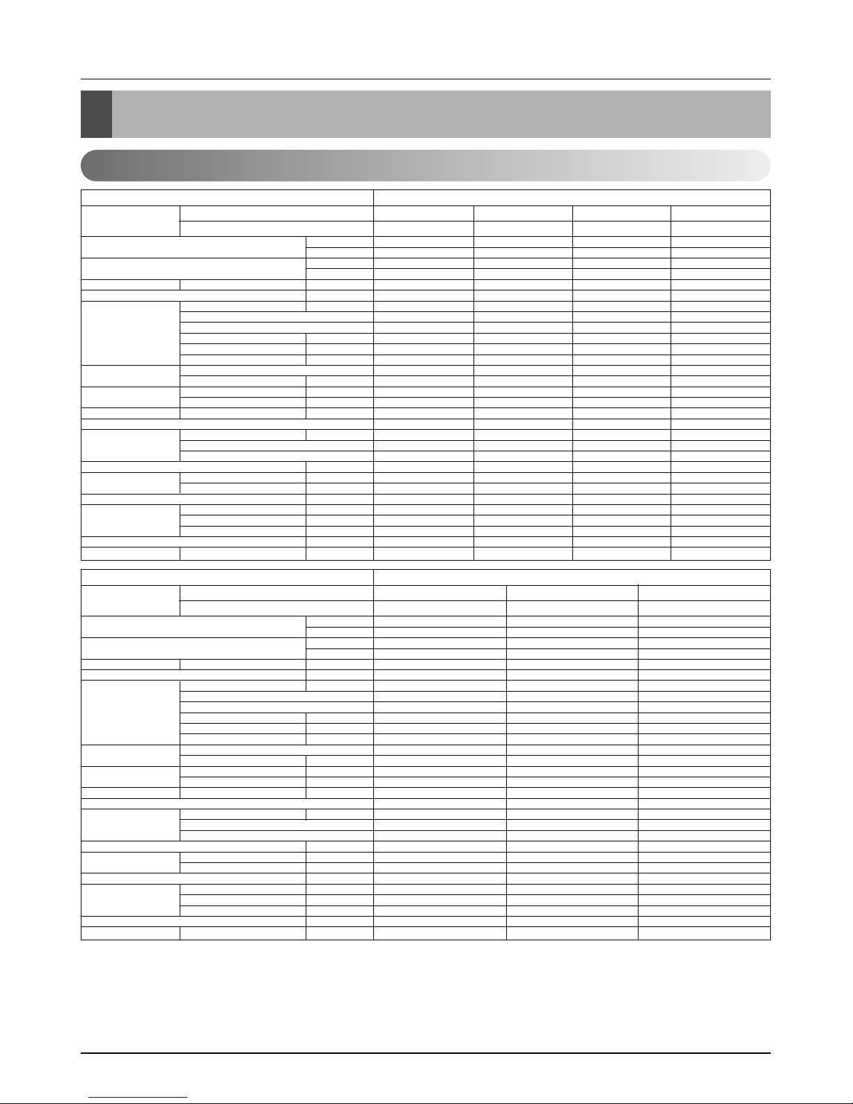
Product Specifications
3024(3517) 4536(5275) 6048(7033) 7056(8205)
12000 18000 24000 28000
3478(4044) 5116(5949) 6955(8089) 8114(9437)
13800 20300 27600 32200
9.5/8/7(336/283/247) 13/12/11(459/424/388) 15/14/13(523/494/459) 19/17/15(671/600/550)
18~30/16~30 18~30/16~30 18~30/16~30 18~30/16~30
18.3 22.4 40.3 48.6
IC-9630LGAE IC-9630LGAC OBM-3502P2 OBM-4105P2
6666
75 90 121 146
0.35 0.75 0.53 0.67
2.5/440 2.5/440 4/440 4/440
Turbo Fan Turbo Fan Turbo Fan Turbo Fan
1/13.0(330) 1/13.0(330) 1/15.0(382) 1/15.0(382)
670/620/550 720/670/620 600/540/480 650/600/550
670/620/550 720/670/620 600/540/480 650/600/550
38 / 35 / 32 41 / 39 / 37 43 / 41 / 39 45 / 42 / 39
Thermistor Thermistor Thermistor Thermistor
0.275(7.0) 0.275(7.0) 0.275(7.0) 0.275(7.0)
19 19 21 21
2R11C 2R11C 2R12C 2R12C
1.2 2.4 3 3.3
22.4*10.5*22.4 (570*269*570) 22.4*10.5*22.4 (570*269*570) 29.3*11.5*29.3 (744*292*744) 29.3*11.5*29. (744*292*744)
26.4*1.2*26.4 (670*30*670) 26.4*1.2*26.4 (670*30*670) 33.5*1.2*33.5 (850*30*850) 33.5*1.2*33.5 (850*30*850)
19(41.9) 19(41.9) 24(52.9) 24(52.9)
1/4(6.35) 1/4(6.35) 1/4(6.35) 1/4(6.35)
3/8(9.52) 1/2(12.7) 1/2(12.7) 5/8(15.88)
1.26(32) 1.26(32) 1.26(32) 1.26(32)
25.2*13.0*25.2 (640*330*640) 25.2*13.0*25.2 (640*330*640) 32.6*14.4*32.6 (828*365*828) 32.6*14.4*32.6 (828*365*828)
189/378 189/378 84/168 84/168
Rated Cooling Capacity kcal/hr(W)
Btu/hr
Ratedl Heating Capacity kcal/hr(W)
Btu/hr
Air Circulation Indoor(H/M/L)
CMM(CFM)
Setting temperature range °C
Fan motor Output W
Model
No. of Poles
Input W
Running Current A
Capacitor µF/Vac
Fan Type
No. Used / Diameter EA/inch(mm)
Fan RPM Cooling(H/M/L) rpm
Heating(H/M/L) rpm
Noise Level
(Sound Press,1m)
H/M/L dBA
Temperature controller
Coil Tube Size (OD) inch(mm)
Fins per inch
No. of Rows & Column
Dehumidification Rate l/h
Dimensions (W*H*D) Indoor inch(mm)
Panel inch(mm)
Net Weight kg(lbs)
Piping Liquid inch(mm)
Connection Gas inch(mm)
Drain hose (ID Ø)mm
Packing Dimension (W*H*D) inch(mm)
Stuffing Quantity
Without(Without) S/Parts 20/40ft
Ceiling Cassette - 4way
ATNH126ELFC
PT-HEC1
ATNH186ELFC
PT-HEC1
ATNH246FLFC
PT-HFC(F)
ATNH306FLFC
PT-HFC(F)
Indoor Unit Type
Model Indoor unit
Decoration panel
9072(10549) 12095(14067) 14112(16412)
36000 48000 56000
10433(12130) 13305(15474) 15523(18053)
41400 52800 61600
25/23/21(883/812/742) 30/28/26(1059/988/918) 34/32/30(1200/1130/1059)
18~30/16~30 18~30/16~30 18~30/16~30
52.5 58.5 107
IC-1630LGPJ IC-1640LGPH IC-14640LGPM
66 6
175 195 237
0.76 1.5 1.8
4/440 6/400 6/400
Turbo Fan Turbo Fan Turbo Fan
1/18.1(460) 1/18.1(460) 1/18.1(460)
550/510/470 600/555/520 700/650/600
550/510/470 600/555/520 700/650/600
40 / 38 / 36 43 / 41 / 39 50 / 47 / 43
Thermistor Thermistor Thermistor
0.275(7.0) 0.275(7.0) 0.275(7.0)
21 21 21
2R 12C 2R 12C 2R 12C
4 5.5 6.5
33.1*11.3*33.1 (840*288*840) 33.1*11.3*33.1 (840*288*840) 33.1*11.3*33.1 (840*288*840)
37.4*1.2*37.4 (950*30*950) 37.4*1.2*37.4 (950*30*950) 37.4*1.2*37.4 (950*30*950)
32(70.4) 32(70.4) 32(70.4)
1/4(6.35) 3/8(9.52) 3/8(9.52)
5/8(15.88) 3/4(19.05) 3/4(19.05)
1.26(32) 1.26(32) 1.26(32)
36.4*13.8*36.4 (925*350*925) 36.4*13.8*36.4 (925*350*925) 36.4*13.8*36.4 (925*350*925)
72/144 72/144 72/144
Rated Cooling Capacity kcal/hr(W)
Btu/hr
Ratedl Heating Capacity kcal/hr(W)
Btu/hr
Air Circulation Indoor(H/M/L)
CMM(CFM)
Setting temperature range °C
Fan motor Output W
Model
No. of Poles
Input W
Running Current A
Capacitor µF/Vac
Fan Type
No. Used / Diameter EA/inch(mm)
Fan RPM Cooling(H/M/L) rpm
Heating(H/M/L) rpm
Noise Level
(Sound Press,1m)
H/M/L dBA
Temperature controller
Coil Tube Size (OD) inch(mm)
Fins per inch
No. of Rows & Column
Dehumidification Rate l/h
Dimensions (W*H*D) Indoor inch(mm)
Panel inch(mm)
Net Weight kg(lbs)
Piping Liquid inch(mm)
Connection Gas inch(mm)
Drain hose (ID Ø)mm
Packing Dimension (W*H*D) inch(mm)
Stuffing Quantity
Without(Without) S/Parts 20/40ft
Ceiling Cassette - 4way
ATNH366DLFC
PT-HDC1
ATNH486DLFC
PT-HC1
ATNH606DLFC
PT-HDC1
Indoor Unit Type
Model Indoor unit
Decoration panel
Product Specifications
Indoor Unit
Notes:
1. Capacities are based on the following conditions:
Cooling : - Indoor Temperature 27˚C(80.6˚F) DB / 19˚C(66.2˚F) WB
- Outdoor Temperature 35˚C(95˚F) DB / 24˚C(75.2˚F) WB
- Interconnecting Piping Length 7.5m
- Level Difference of Zero.
Heating : - Indoor Temperature 20˚C(68˚F) DB / 15˚C(59˚F) WB
- Outdoor Temperature 7˚C(44.6˚F) DB / 6˚C(42.8˚F) WB
- Interconnecting Piping Length 7.5m
- Level Difference of Zero.
2. Capacities are Net Capacities.
3. Due to our policy of innovation some specifications may be changed without notification.
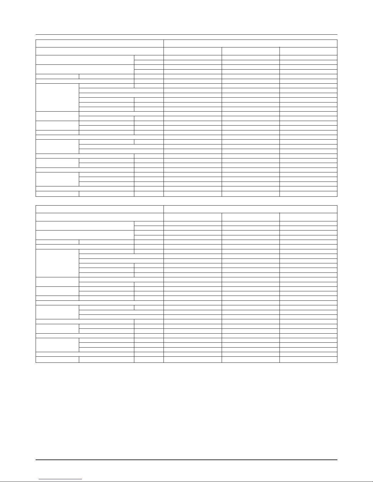
22 Synchro Air Conditioner
Product Specifications
4536(5275) 6048(7034) 7560(8791)
18000 24000 30000
5116(5949) 6955(8089) 8694(10110)
20300 27600 34500
16.5/14.5/13(583/512/459) 18/16.5/14(636/583/494) 26.5/23/20(936/812/706)
8810
18~30/16~30 18~30/16~30 18~30/16~30
118 118 211
IC-13450LG13C IC-13450LG13C IC-13450LG13J
44 4
180 180 300
0.92 0.92 1.34
6/370 6/370 6/370
Sirocco Fan Sirocco Fan Sirocco Fan
2/6.97(177) 2/6.97(177) 2/6.97(177)
1350/1310/1270 1410/1350/1250 1415/1360/1290
1350/1310/1270 1410/1350/1250 1415/1360/1290
36 / 34 /32 38 / 36 /34 40 / 38 /35
Thermistor Thermistor Thermistor
0.275(7.0) 0.275(7.0) 0.275(7.0)
21 21 21
2R 10C 3R 10C 3R 12C
2 2.5 3.3
34.6*10.2*17.7 (880*260*450) 34.6*10.2*17.7 (880*260*450) 46.5*11.7*17.7 (1180*298*450)
35(77.2) 35(77.2) 38(84)
1/4(6.35) 1/4(6.35) 1/4(6.35)
1/2(12.7) 1/2(12.7) 5/8(15.88)
25.4 25.4 25.4
44.7*13.4*22.0 (1135*340*565) 44.7*13.4*22.0 (1135*340*565) 56.5*14.8*22.9 (1435*375*582)
120/252 120/252 95/191
Rated Cooling Capacity kcal/hr(W)
Btu/hr
Ratedl Heating Capacity kcal/hr(W)
Btu/hr
Air Circulation Indoor(H/M/L)
CMM(CFM)
Setting temperature range °C
Fan motor Output W
Model
No. of Poles
Input W
Running Current A
Capacitor µF/Vac
Fan Type
No. Used / Diameter EA/inch(mm)
Fan RPM Cooling(H/M/L) rpm
Heating(H/M/L) rpm
Noise Level
(Sound Press,1m)
H/M/L dBA
Temperature controller
Coil Tube Size (OD) inch(mm)
Fins per inch
No. of Rows & Column
Dehumidification Rate l/h
Dimensions (W*H*D) Indoor inch(mm)
Panel inch(mm)
Net Weight kg(lbs)
Piping Liquid inch(mm)
Connection Gas inch(mm)
Drain hose (ID Ø)mm
Packing Dimension (W*H*D) inch(mm)
Stuffing Quantity
Without(Without) S/Parts 20/40ft
Ceiling Concealed Duct - High Static
ABNH186HLAC ABNH246HLAC ABNH306GLAC
Indoor Unit Type
Model
9072(10549) 12095(14067) 14112(16412)
36000 48000 56000
10433(12130) 13305(15474) 15523(18053)
41400 52800 61600
32/29/26(1130/1024/918) 40/35/30(1413/1236/1059) 50/45/40(1766/1413/1236)
10 15 15
18~30/16~30 18~30/16~30 18~30/16~30
272 431 431
IC-13470LG13A Y002276-1 Y002276-1
44 4
323 818 818
1.42 3.65 3.65
6/370 15/450 15/450
Sirocco Fan Sirocco Fan Sirocco Fan
2/6.97(177) 2/9.1(230) 2/9.1(230)
1415/1360/1290 1063/1035/983 1113/1063/1035
1415/1360/1290 1063/1035/983 1113/1063/1035
42 / 39 /36 44/42/40 46/44/42
Thermistor Thermistor Thermistor
0.275(7.0) 0.375(9.52) 0.375(9.52)
21 19 19
3R 12C 3R13C 4R13C
4 6 6.5
46.5*11.7*17.7 (1180*298*450) 48.4*15.0*23.2 (1230*380*590) 48.4*15.0*23.2 (1230*380*590)
38(84) 60(132) 60(132)
1/4(6.35) 3/8(9.52) 3/8(9.52)
5/8(15.88) 3/4(19.05) 3/4(19.05)
25.4 25.4 25.4
56.5*14.8*22.9 (1435*375*582) 56.9*17.9*27.6 (1445*455*700) 56.9*17.9*27.6 (1445*455*700)
95/191 57/120 57/120
Rated Cooling Capacity kcal/hr(W)
Btu/hr
Ratedl Heating Capacity kcal/hr(W)
Btu/hr
Air Circulation Indoor(H/M/L)
CMM(CFM)
Setting temperature range °C
Fan motor Output W
Model
No. of Poles
Input W
Running Current A
Capacitor µF/Vac
Fan Type
No. Used / Diameter EA/inch(mm)
Fan RPM Cooling(H/M/L) rpm
Heating(H/M/L) rpm
Noise Level
(Sound Press,1m)
H/M/L dBA
Temperature controller
Coil Tube Size (OD) inch(mm)
Fins per inch
No. of Rows & Column
Dehumidification Rate l/h
Dimensions (W*H*D) Indoor inch(mm)
Panel inch(mm)
Net Weight kg(lbs)
Piping Liquid inch(mm)
Connection Gas inch(mm)
Drain hose (ID Ø)mm
Packing Dimension (W*H*D) inch(mm)
Stuffing Quantity
Without(Without) S/Parts 20/40ft
Ceiling Concealed Duct - High Static
ABNH366GLAC ABNH486RLAC ABNH606RLAC
Indoor Unit Type
Model
Notes:
1. Capacities are based on the following conditions:
Cooling : - Indoor Temperature 27˚C(80.6˚F) DB / 19˚C(66.2˚F) WB
- Outdoor Temperature 35˚C(95˚F) DB / 24˚C(75.2˚F) WB
- Interconnecting Piping Length 7.5m
- Level Difference of Zero.
Heating : - Indoor Temperature 20˚C(68˚F) DB / 15˚C(59˚F) WB
- Outdoor Temperature 7˚C(44.6˚F) DB / 6˚C(42.8˚F) WB
- Interconnecting Piping Length 7.5m
- Level Difference of Zero.
2. Capacities are Net Capacities.
3. Due to our policy of innovation some specifications may be changed without notification.

Service Manual 23
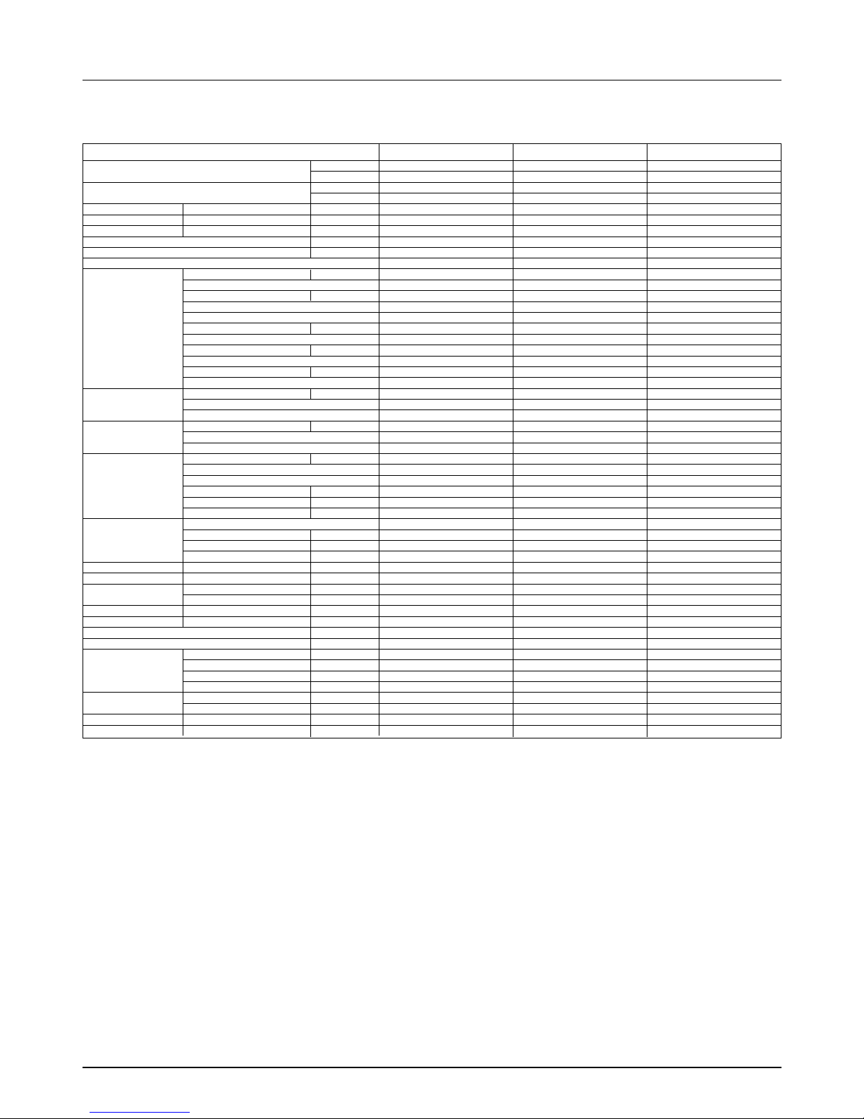
Product Specifications
Rated Cooling Capacity kcal/hr(W)
Btu/hr
Ratedl Heating Capacity kcal/hr(W)
Btu/hr
Air Circulation Indoor(H/M/L)
CMM(CFM)
Setting temperature range °C
Fan motor Output W
Model
No. of Poles
Input W
Running Current A
Capacitor µF/Vac
Fan Type
No. Used / Diameter EA/inch(mm)
Fan RPM Cooling(H/M/L) rpm
Heating(H/M/L) rpm
Noise Level
(Sound Press,1m)
H/M/L dBA
Temperature controller
Coil Tube Size (OD) inch(mm)
Fins per inch
No. of Rows & Column
Dehumidification Rate l/h
Dimensions (W*H*D) Indoor inch(mm)
Net Weight kg(lbs)
Piping Liquid inch(mm)
Connection Gas inch(mm)
Drain hose (ID Ø)mm
Packing Dimension (W*H*D) inch(mm)
Stuffing Quantity
Without(Without) S/Parts 20/40ft
3024(3517) 4536(5274) 6048(7032) 6653(7377)
12000 18000 24000 26400
3478(4044) 5116(5949) 6955(8089) 7635(8880)
13800 20300 27600 30300
10.0/8.3/6.5(353/293/230) 13.5/12/11(477/424/388) 15/13.5/12(530/477/424) 18/16/14(636/564/494)
18~30/16~30 18~30/16~30 18~30/16~30 18~30/16~30
17.5 30 35 42.5
IC-18422LG31A IC-9430LGCG IC-9430LGCE OBM-3019P2
4444
43 53 63 81
0.23 0.23 0.27 0.38
1.5/370 1.5/370 1.5/370 1.5/370
Cross Flow Fan Cross Flow Fan Cross Flow Fan Cross Flow Fan
1/3.7(95) 1/3.1(80) 1/3.1(80) 1/3.1(80)
1240/1120/900 1090/990/890 1160/1060/960 1220/1110/1010
1240/1120/900 1090/990/890 1160/1060/960 1220/1110/1010
40 / 36 / 31 43 / 40 / 37 45 / 42 / 39 45 / 42 / 39
Thermistor Thermistor Thermistor Thermistor
0.197(5.0) 0.275(7.0) 0.275(7.0) 0.275(7.0)
20 18 20 20
2R 12C 2R 12C 2R 14C 2R 14C
1.2 2.3 3.2 3.5
35.4*7.9*19.3 (900*200*490) 47.2*8.1*24.2 (1200*205*615) 47.2*8.1*24.2 (1200*205*615) 47.2*8.1*24.2 (1200*205*615)
12(26.5) 30(66.1) 30(66.1) 30(66.1)
1/4(6.35) 1/4(6.35) 1/4(6.35) 1/4(6.35)
3/8(9.52) 1/2(12.7) 1/2(12.7) 5/8(15.88)
20 20 20 20
38.2*11.2*22.2 (970*285*565) 50.8*11.4*27.4 (1272*290*696) 50.8*11.4*27.4 (1272*290*696) 50.8*11.4*27.4 (1272*290*696)
189/383 102/219 102/219 102/219
Ceiling & Floor (Convertible)
AVNH126ELAC AVNH186BLAC AVNH246BLAC AVNH306BLAC
Indoor Unit Type
Model
Notes:
1. Capacities are based on the following conditions:
Cooling : - Indoor Temperature 27˚C(80.6˚F) DB / 19˚C(66.2˚F) WB
- Outdoor Temperature 35˚C(95˚F) DB / 24˚C(75.2˚F) WB
- Interconnecting Piping Length 7.5m
- Level Difference of Zero.
Heating : - Indoor Temperature 20˚C(68˚F) DB / 15˚C(59˚F) WB
- Outdoor Temperature 7˚C(44.6˚F) DB / 6˚C(42.8˚F) WB
- Interconnecting Piping Length 7.5m
- Level Difference of Zero.
2. Capacities are Net Capacities.
3. Due to our policy of innovation some specifications may be changed without notification.
24 Synchro Air Conditioner
Product Specifications
Cooling Capacity kcal/hr(W)
Btu/hr
Heating Capacity kcal/hr(W)
Btu/hr
Input Cooling/Heating W
Running Current Cooling/Heating A
Starting Current Cooling/Heating A
Power Supply Ø,V,Hz
Power Factor %
Number of Connectable Indoor Units
Compressor Locked Rotor Amp. A
Type
Quantity No
Model
Maker
Capacity kcal/hr(Btu/hr)
Motor Type
Motor Input W
Oil Type
Oil Charge cc
O.L.P Type(model name)
Refrigerant Charge * g(oz)
Type
Control
Outdoor Coil Tube Size (OD) inch(mm)
Fins per inch
No. of Rows & Column/No.
Outdoor fan motor Output W
Model
No. Used / No. of Poles
Input W
Running Current A
Capacitor µF/Vac
Outdoor Fan Type
No. Used / Diameter EA/inch(mm)
Discharge Side / Top
Speed rpm
Air Circulation Outdoor CMM(CFM)
Noise Level(Sound Press,1m)
Outdoor dB(A)±1
SVC Valve Liquid inch(mm)
Gas inch(mm)
Dimensions W*H*D inch(mm)
Net Weight Outdoor kg(lbs)
Power Supply Cable No.* mm
2
Connecting Cable No.* mm
2
Max Interunit Total Piping m
Piping Length Total Main Piping m
Total Branch Piping m
For One Room m
Max. Installation Indoor Unit - Outdoor Unit m
Height Difference Indoor Unit - Indoor Unit m
Packing Dimension (W*H*D) inch(mm)
Stuffing Quantity With(Without) S/Parts 20/40ft
12096(14607) 18144(21101) 24192(28135)
48000 72000 96000
13305(15474) 19958(23211) 27820(32355)
52800 79200 110400
5300 / 5050 8000 / 7700 11100 / 11000
10.0 / 9.5 14.7 / 14.4 20 / 19.7
---
3,380~415,50 3,380~415,50 3,380~415,50
82 80 83
Single / Duo / Trio / Quartet Duo / Trio / Quartet Duo / Trio / Quartet
42 at 420V 24 / 27 63 at 420V
Rotary Rotary Scroll
232
GPT330YAA 5JS290PBA21 AR061YAA
LG Matsushita Electric LG
6854(27200) at 50Hz & 380V 6376(25301) at 50Hz & 380V 12625(50100) at 50Hz & 380V
Three Phase Induction Motor Three Phase Induction Motor Three Phase Induction Motor
2550 2680 5330
FVC68D(PVE) FV50S(PVE) FVC68D(PVE)
1200 1130 1800
Internal Type(UBUKATA) IT(Internal Thermostat) Internal Type(UP18TA057)
4200(148.1) 7100(250.4) 7800(275.1)
R-410A R-410A R-410A
L.E.V L.E.V L.E.V
0.276(7.0) 0.276(7.0) 0.276(7.0)
17 17 18
2R 52C
2R 17C + 3R 36C + 2R 17C + 2R 36C 2R 17C + 1R 36C + 2R 17C + 2R 36C
70 271 271
AMR071B9 ARE676E01 ARE676E01
2/6 1/6 2/6
168 429 429
- 1.87 1.87
6/370 10/370 10/370
Propeller Propeller Propeller
2/18.1(460) 1/20.7(526) 2/20.7(526)
Side Discharge Top Discharge Top Discharge
900 850 850
53(1872*2) 90(3179) 185(6533)
56 58 60
3/8 (9.52) 3/8 (9.52) 1/2 (12.7)
3/4 (19.05) 1 (25.4) 1 (25.4)
35.4*45.8*14.5(900*1165*370) 31.5*56.7*27.1(800*1440*690) 50.4*56.7*27.1(1280*1440*690)
105(231) 150(331) 299(659)
5*5.5 (Includes earth) 5*5.5 (Includes earth) 5*5.5 (Includes earth)
4*0.75 (Includes earth) 4*0.75 (Includes earth) 4*0.75 (Includes earth)
110 110 110
50 50 50
60 60 60
15 15 15
30 30 30
111
41.7*48.0*18.3(1060*1220*465) 34.4*61.0*29.7(875*1550*755) 53.1*62.6*29.9(1350*1590*760)
27 / 55 18 / 39 12 / 25
AUUH488C AUUH728C AUUH1008C
Model
Notes:-
1. Capacities are based on the following conditions:
Cooling: - Indoor Temperature 27˚C(80.6ÜV) DB /19˚C(66.2ÜV) WB
- Outdoor Temperature 35˚C(95ÜV) DB /24˚C(75.2ÜV) WB
Heating: - Indoor Temperature 20˚C(68ÜV) DB / 15˚C(59ÜV) WB
- Outdoor Temperature 7˚C(44.6ÜV) DB / 6˚C(42.8ÜV) WB
Piping Length - Interconnecting Pipe Length 7.5m(25ft)
- Level Difference of Zero
2. * : Full factory charge is shipped in the outdoor unit. Chargeless for 30m of piping length.
3. Due to our policy of innovation some specifications may be changed without notification.
Service Manual 25
Combination table
Combination table
MPS Variable
AUUH728CAUUH488C
Synchro Combination(k Btu/h) Total(k Btu/h) Branch Kit
Duo(2 Unit)
Trio(3 Unit)
Quartet
(4 Unit)
30 + 36(2:3)
36 + 36(1:1)
18 + 24 + 24(1:2:2)
18 + 18 + 36(1:1:2)
24 + 24 + 24(1:1:1)
24 + 24 + 30(1:1:2)
18 + 18 + 18 + 18
(1:1:1:1)
68
72
66
72
72
78
72
PMUB122A
PMUB112A
PMUB111A
PMUB112A
PMUB1111A
PMUB23A
PMUB11A
Synchro Combination(k Btu/h) Total(k Btu/h) Branch Kit
Single
(1 Unit)
Trio
(3 Unit)
Duo
(2 Unit)
Quartet
(4 Unit)
48
18 + 18 + 18 (1:1:1)
12 + 12 + 12 + 12 (1:1:1:1)
18 + 24 (2:3)
24 + 24 (1:1)
24 + 30 (2:3)
48
54
42
48
54
48
PMUB23A
PMUB11A
PMUB23A
PMUB1111A
PMUB111A
-
AUUH1008C
Synchro Combination(k Btu/h) Total(k Btu/h) Branch Kit
Duo(2 Unit)
Trio(3 Unit)
Quartet
(4 Unit)
36 + 48 (2:3)
36 + 60 (2:3)
48 + 48 (1:1)
24 + 24 + 36(1:1:2)
24 + 24 + 30(1:1:2)
30 + 30 + 30(1:1:1)
30 + 30 + 36(1:1:2)
30 + 36 + 36(1:2:2)
24 + 24 +24 + 24
(1:1:1:1)
84
96
96
84
84
90
96
102
96
PMUB112A
PMUB112A
PMUB111A
PMUB112A
PMUB122A
PMUB1111A
PMUB23A
PMUB23A
PMUB11A
26 Synchro Air Conditioner
Installation
Installation
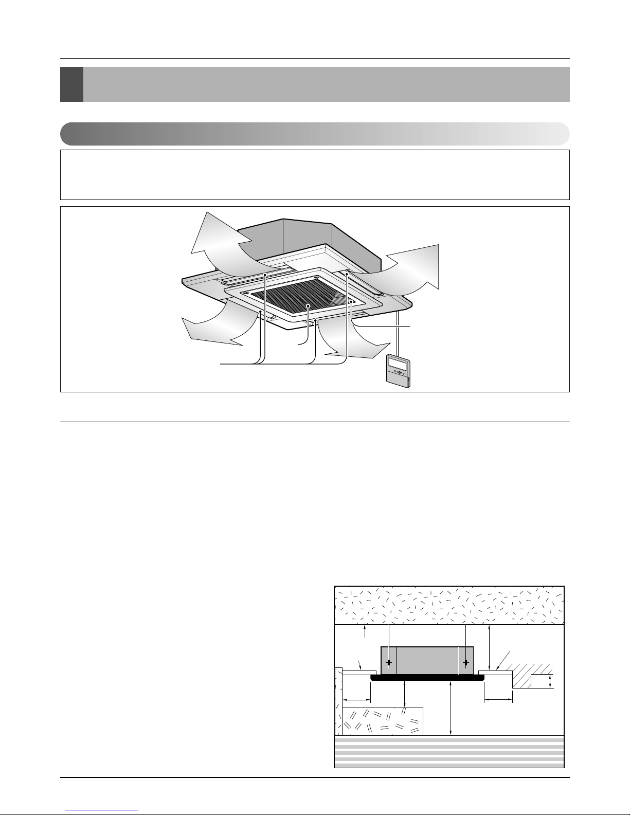
Indoor Unit_Cassette Type
• Please read this instruction sheet completely before installing the product.
• When the power cord is damaged, replacement work shall be performed by authorized personnel only.
• Installation work must be performed in accordance with the national wiring standards by authorized personnel only.
Anti-bacteria filter
Air
Intake
Air Outlet
Required Parts Required Tools
• Connecting cable
• Pipes: Gas side
Liquid side
• Hanging Bolt
(W 3/8 or M10 length 650mm)
• Insulated drain hose
• Additional Drain hose
(Inner Diameter...........................32mm)
• Level
• Screw driver
• Electric drill
• Hole core drill (ø70mm)
• Flaring Tools set
• Torque Wrenches
• Hexagonal Wrench (4mm, 5mm)
• Gas-leak detector
• Owner’s Manual
• Thermometer
1. Selection of the best location
• There should not be any heat source or steam near the
unit.
• There should not be any obstacles to the air circulation.
• There should be provision of easy condensate drain.
• Taking into accounting the noise prevention criteria,
spot the installation location.
• Do not install the unit near the door way.
• Keep proper distances, of the unit, from ceiling, fence,
floor, walls and other obstacles as shown in figure.
• The indoor unit must have the maintenance space.
Unit:cm
Ceiling
Ceiling Board
Ceiling Board
30 or more
Above 250
400 or less
100
or more
50 or
more
50 or
more
30 or less
Floor
Read completely, than follow step by step.
Service Manual 27
Installation
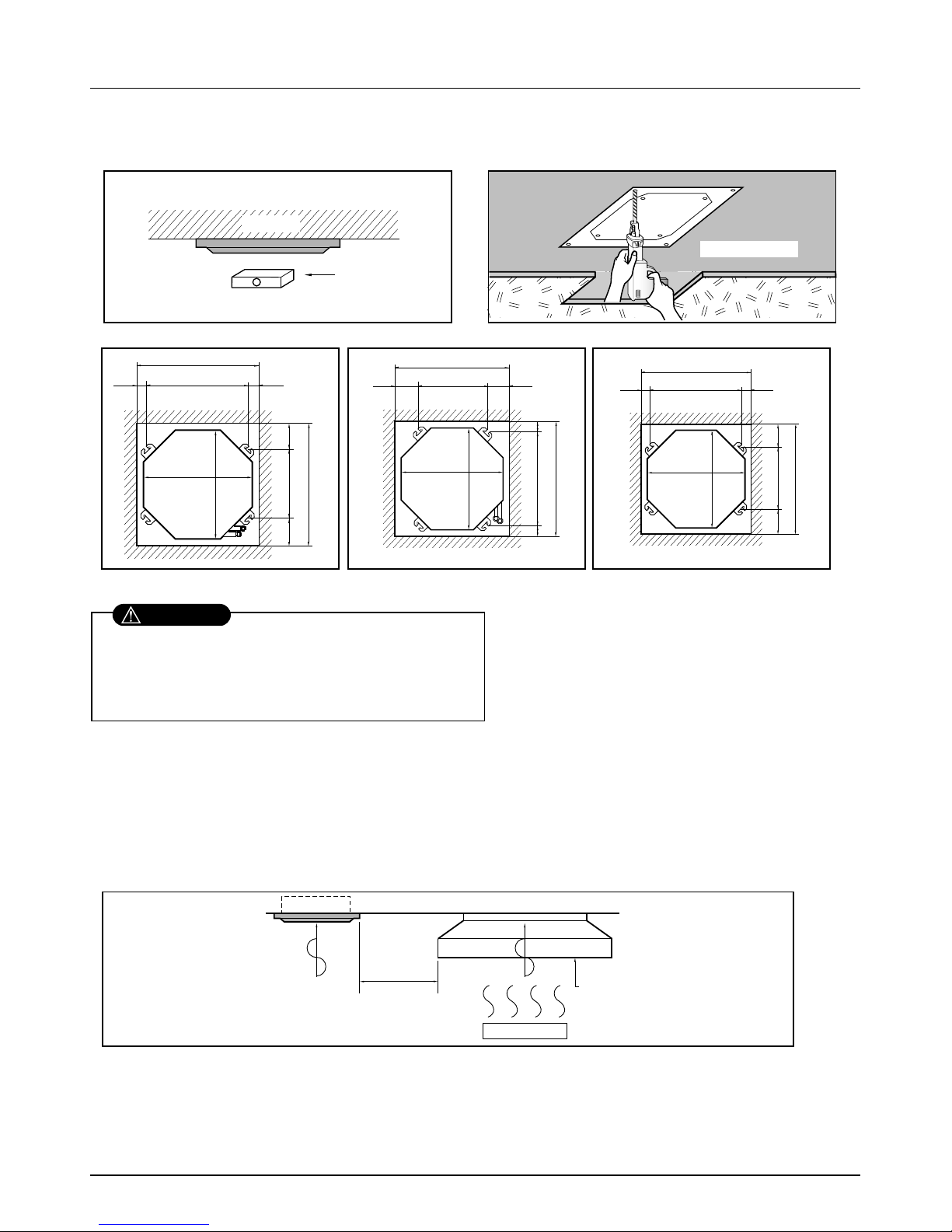
2. Ceiling opening dimensions and hanging bolt location
NOTE:
• Avoid the following installation location.
1. Such places as restaurants and kitchen where considerable amount of oil steam and flour is generated.
These may cause heat exchange efficiency reduction, or water drops, drain pump mal-function.
In these cases, take the following actions;
• Make sure that ventilation fan is enough to cover all noxious gases from this place.
• Ensure enough distance from the cooking room to install the air conditioner in such a place where it may not suck oily steam.
Ceiling board
Level gauge
Ceiling
Unit:mm
570 Unit size
570 Unit size
672 (Hanging bolt)
7575
600 (Ceiling opening)
600 (Ceiling opening)
521(Hanging bolt)
39.5
39.5
TE Model TF Model TD Model
Unit:mm
744 Unit size
744 Unit size
658 (Hanging bolt)
6666
790 (Ceiling opening)
790 (Ceiling opening)
572(Hanging bolt)
109
109
Unit:mm
840 Unit size
840 Unit size
672 (Hanging bolt)
101.5101.5
875 (Ceiling opening)
875 (Ceiling opening)
785(Hanging bolt)
45
45
• The dimensions of the paper pattern for installation are the same as those of the ceiling opening dimensions.
• This air-conditioner uses a drain pump.
• Install the unit horizontally using a level gauge.
• During the installation, care should be taken not to
damage electric wires.
CAUTION
2. Avoid installng air conditioner in such places where cooking oil or iron powder is generated.
3. Avoid places where inflammable gas is generated.
4. Avoid place where noxious gas is generated.
5. Avoid places near high frequency generators.
Use the ventilation fan
for smoke-collecting
hood with sufficient
capacity.
Cooking table
Air conditioner
Take enough
distance
• Select and mark the position for fixing bolts and
piping hole.
• Decide the position for fixing bolts slightly tilted to
the drain direction after considering the direction
of drain hose.
• Drill the hole for anchor bolt on the wall.
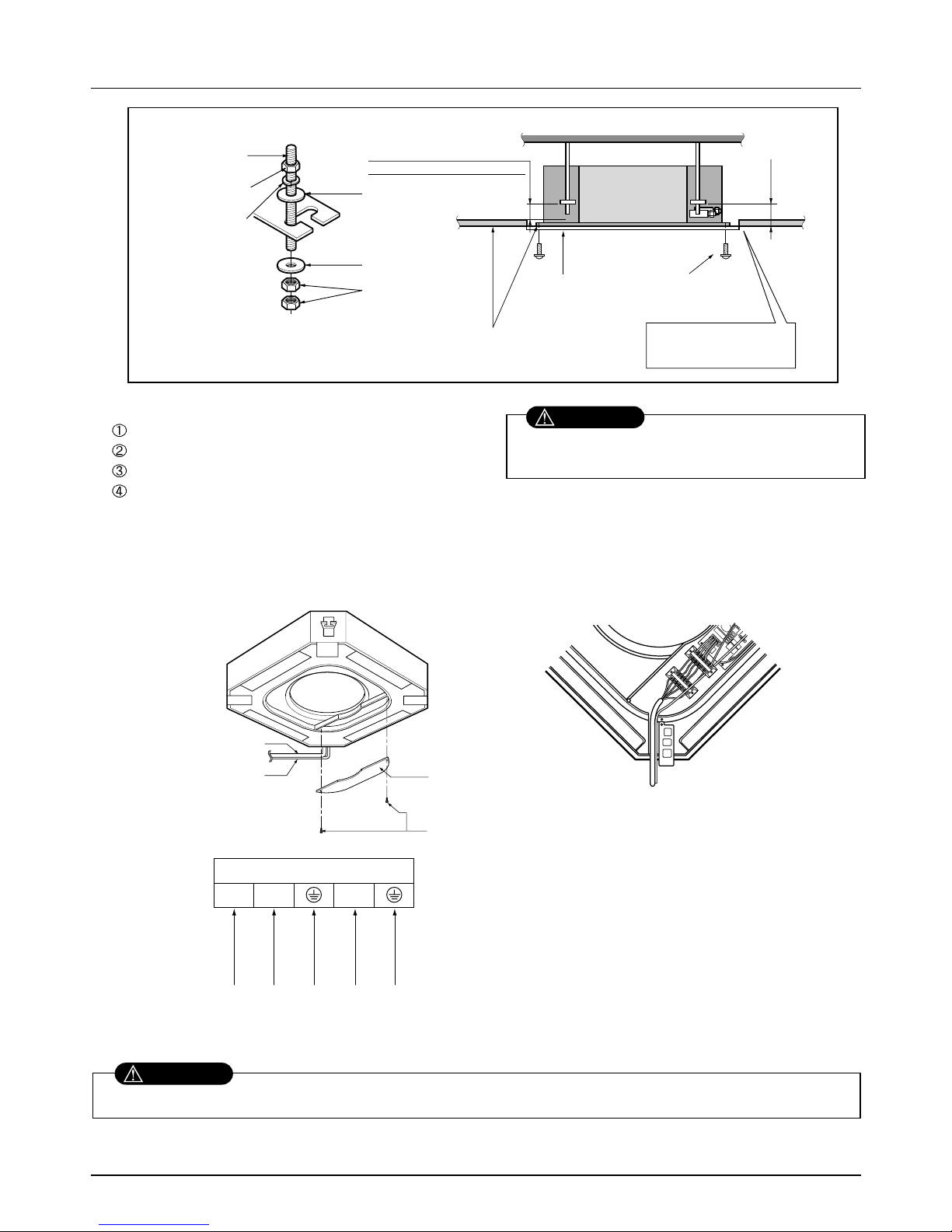
28 Synchro Air Conditioner
Installation
Set screw of
paper pattern (4 pieces)
Paper pattern
for installation
Ceiling board
150mm
Adjust the same height
Ceiling board
Ceiling
Flat washer for M10
(accessory)
Keep the length of the bolt
from the bracket to 40mm
Open the ceiling board
along the outer edge of the
paper pattern.
Flat washer for M10
(accessory)
Hanging bolt
(W3/8 or M10)
Nut
(W3/8 or M10)
Nut
(W3/8 or M10)
Spring washer
(M10)
Air Conditioner body
• The following parts are local purchasing.
Hanging Bolt - W 3/8 or M10
Nut - W 3/8 or M10
Spring Washer - M10
Plate Washer - M10
• Tighten the nut and bolt to prevent unit from
falling off.
CAUTION
[Air inlet side view]
Control box cover
Indoor
power cord
Remote
controller
cord
Control box cover
fitting screw(2 units)
Terminal Block in Indoor
1(L) 2(N) 3
Connected to outdoor unit
3. Wiring Connection
• Open the control box cover and connect the remote control cord and Indoor power wires.
Make sure that the screws of the terminal are free from looseness.
WARNING
Service Manual 29
Installation
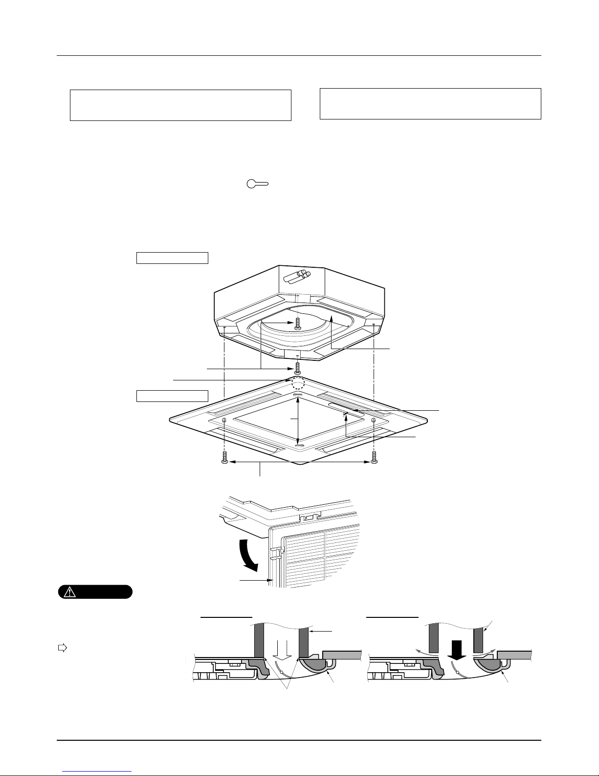
4. Installation of Decoration Panel
1. Temporarily fix two decoration panel fixing screws (hexagon M5 screw) on the unit body. (Tighten by
amount 10mm in length.)
The fixing screws (hexagon M5 screw) are included the indoor unit box.
2. Remove the air inlet grille from the decoration panel. (Remove the hook for the air inlet grille cord.)
3. Hook the decoration panel key hole ( ) on the screws fixed in step above, and slide the panel so
that the screws reach the key hole edge.
4. Retighten completely two temporarily fixed screws and other two screws. (Total 4 screws)
5. Connect the louver motor connector and display connector.
6. After tightening these screws, install the air inlet grille (including the air filter).
Decoration panel fixing screws
(hexagon M5 screws)
Temporally fitting at 2 places
(Tightening about 10mm)
Control box cover
Piping side
Inlet GrilleInlet GrilleInlet Grille
Inlet GrilleInlet Grille
Louver motor
Decoration panel fixing screws
(Hexagon M5 screw)
Air conditioner unit
Decoration panel
Key holes
Display
Lead wire for
louver motor and
display
The decoration panel has its installation
direction.
Before installing the decoration panel,
always remove the paper template.
CAUTION
Install certainly the decoration
panel.
Cool air leakage causes sweating.
Water drops fall.
Air conditioner
unit
Ceiling
board
Decoration panel
Decoration
panel
Fit the insulator (this part) and
be careful for cool air leakage
Good example
Air
Cool air leakage
(no good)
Bad example
Ceiling
board
Air conditioner unit
30 Synchro Air Conditioner
Installation
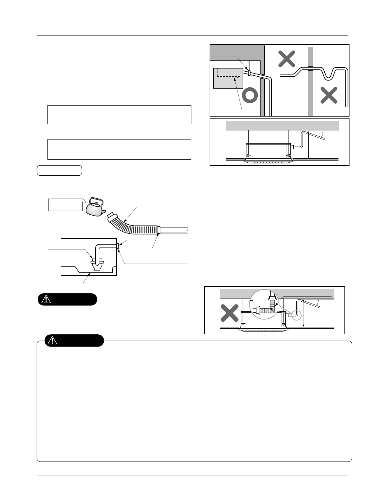
5. Indoor Unit Drain Piping
• Drain piping must have down-slope (1/50 to 1/100): be sure
not to provide up-and-down slope to prevent reversal flow.
• During drain piping connection, be careful not to exert extra
force on the drain port on the indoor unit.
• The outside diameter of the drain connection on the indoor
unit is 32mm.
•
Be sure to install heat insulation on the drain piping.
Piping material: Polyvinyl chloride pipe VP-25
and pipe fittings
The air conditioner uses a drain pump to drain water.
Use the following procedure to test the drain pump operation:
• Connect the main drain pipe to the exterior
and leave it provisionally until the test
comes to an end.
• Feed water to the flexible drain hose and
check the piping for leakage.
• Be sure to check the drain pump for normal
operating and noise when electrical wiring
is complete.
• When the test is complete, connect the
flexible drain hose to the drain port on the
indoor unit.
Heat insulation material: Polyethylene foam with
thickness more than 8 mm.
Drain test
Maintenance
drain port
Upward
routing
not allowed
Pipe clamp
Indoor unit
1/50~1/100
MAX 700mm
Feed water
Drain Pump
Drain pan
Flexible drain hose
(accessory)
Main
drain pipe
Glue the joint
Drain
port
Drain hose connection
Use the clip (accessory)
CAUTION
The supplied flexible drain hose should not be curved,
neither screwed. The curved or screwed hose may
cause a leakage of water.
1/50~1/100
MAX 700mm
Flexible drain hoseFlexible drain hose
After the confirmation of the above conditions, prepare the wiring as follows:
1) Never fail to have an individual power specialized for the air conditioner. As for the method of wiring, be guided by the
circuit diagram pasted on the inside of control box cover.
2) Provide a circuit breaker switch between power source and the unit.
3) The screw which fasten the wiring in the casing of electrical fittings are liable to come loose from vibrations to which the
unit is subjected during the course of transportation. Check them and make sure that they are all tightly fastened. (If they
are loose, it could give rise to burn-out of the wires.)
4) Specification of power source
5) Confirm that electrical capacity is sufficient.
6) Be sure that the starting voltage is maintained at more than 90 percent of the rated voltage marked on the name plate.
7) Confirm that the cable thickness is as specified in the power sources specification.
(Particularly note the relation between cable length and thickness.)
8) Never fail to equip a leakage breaker where it is wet or moist.
9) The following troubles would be caused by voltage drop-down.
• Vibration of a magnetic switch, damage on the contact point there of, fuse breaking, disturbance to the normal function of a
overload protection device.
• Proper starting power is not given to the compressor.
CAUTION
 Loading...