


OWNER’S MANUAL
MONITOR SIGNAGE
Please read this manual carefully before operating your set and retain it
for future reference.
MONITOR SIGNAGE MODELS
84WS70BS
84WS70MS
www.lg.com

TABLE OF CONTENTS
2
ENGLISH
TABLE OF CONTENTS
ENG
3 LICENSES
4 ASSEMBLING AND
4 Accessories
5 Optional Accessories
6 Parts and buttons
8 Portrait Layout
8 Using the Mounting Cable Tie
9 Connecting the Eye-Bolt Bracket
10 Connecting the Media Player
11 Connecting an Optional Box
12 Mounting on a wall
14 REMOTE CONTROL
16 Change Device Name
16 SimpLink Setting
PREPARING
31 CUSTOMIZING SETTINGS
31 - PICTURE settings
35 Using the additional options
35 - Adjusting aspect ratio
37 - SOUND settings
38 - TIME settings
39 - OPTION settings
41 - NETWORK settings
41 - SUPPORT settings
42 MAKING CONNECTIONS
43 External Device Connection
43 - HDMI connection
44 - AV(CVBS) connection
45 Connecting to a USB
45 Connecting to the LAN
46 Daisy Chain Monitors
17 USING THE MONITOR
17 Connecting to a PC
18 - RGB connection
18 - DVI-D connection
19 - HDMI connection
19 - Display Port connection
20 - Using the Input List
21 ENTERTAINMENT
21 - Connecting to a wired network
22 - Network Status
23 - Connecting USB storage devices
25 - Using My Media
27 - Playing video
29 - Viewing photos
30 - Listening to music
47 TROUBLESHOOTING
50 SPECIFICATIONS
54 IR CODES
55 CONTROLLING THE MULTIPLE
PRODUCT
55 Connecting the cable
55 RS-232C Configurations
55 Communication Parameter
56 Command reference list
58 Transmission/ Receiving protocol

LICENSES
3
LICENSES
Supported licenses may differ by model. For more information of the licenses, visit
The terms HDMI and HDMI High-Definition Multimedia Interface, and the
HDMI logo are trademarks or registered trademarks of HDMI Licensing LLC
in the United States and other countries.
This DivX Certified® device has passed rigorous testing to ensure it plays
DivX® video.
To play purchased DivX movies, first register your device at
Find your registration code in the DivX VOD section of your device setup
menu.
DivX Certified® to play DivX® video up to HD 1080p, including premium
content.
DivX®, DivX Certified® and associated logos are trademarks of DivX, LLC and
are used under license.
Covered by one or more of the following U.S. patents:
7,295,673; 7,460,668; 7,515,710; 7,519,274.
Manufactured under license from Dolby Laboratories. Dolby and the double-D
symbol are trademarks of Dolby Laboratories.
www.lg.com.
vod.divx.com
ENGLISH
.
For DTS patents, see
from DTS Licensing Limited. DTS, the Symbol, & DTS and the Symbol
together are registered trademarks, and DTS 2.0 Channel is a trademark of
DTS, Inc. © DTS, Inc. All Rights Reserved.
http://patents.dts.com
. Manufactured under license
NOTE
The warranty will not cover any damages caused by using the product in an excessively dusty
environment.
ASSEMBLING AND PREPARING
4
ENGLISH
ASSEMBLING AND PREPARING
ENG
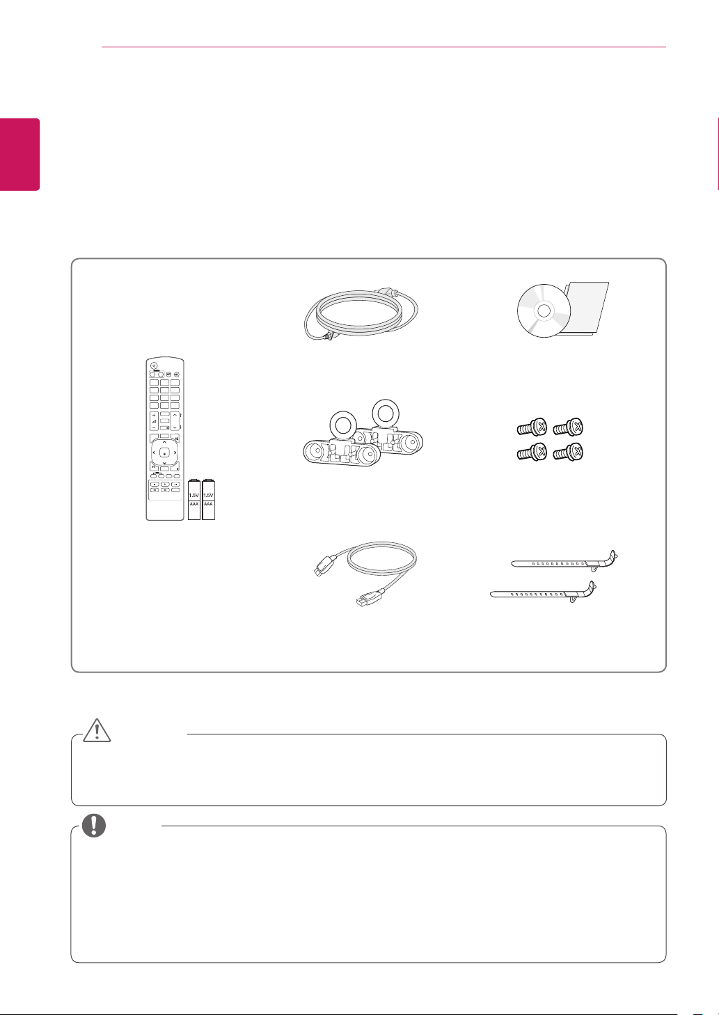
Accessories
Check your product box for the following items. If there are any missing accessories, contact the local
dealer where you purchased your product. The illustrations in this manual may differ from the actual product
and accessories.
POWER
INPUT
ENERGY
MONITOR
OFF
ON
. , !ABCDEF
GHIJKLMNO
PQRSTUV
1/a/A
MUTE
AUTO
MENU
BACK
ID
OFF
ON
SAVING
WXYZ
CLEAR
- * #
MARK
ARC
P
A
BRIGHT
PSM
G
NESS
E
S.MENU
OK
EXIT
TILE
Power Cord
Eye-Bolt Bracket (2 EA) M4 x L12 Screw (4 EA)
CD (Owner's Manual)/ Card
For Eye-Bolt Bracket
Remote control and
Batteries
DP Cable
Mounting Cable Tie (2 EA)
CAUTION
Do not use any unauthorized or aftermarket items to ensure the safety and product life span.
Any damages or injuries by using unauthorized or aftermarket items are not covered by the warranty.
NOTE
The accessories supplied with your product may vary depending on the model.
Product specifications or contents in this manual may be changed without prior notice due to upgrade
of product functions.
SuperSign software and manual.
- Downloading from the LG Electronics website.
- Visit the LG Electronics website (
software for your model.
http://www.lgecommercial.com/supersign
) and download the latest
ASSEMBLING AND PREPARING
5
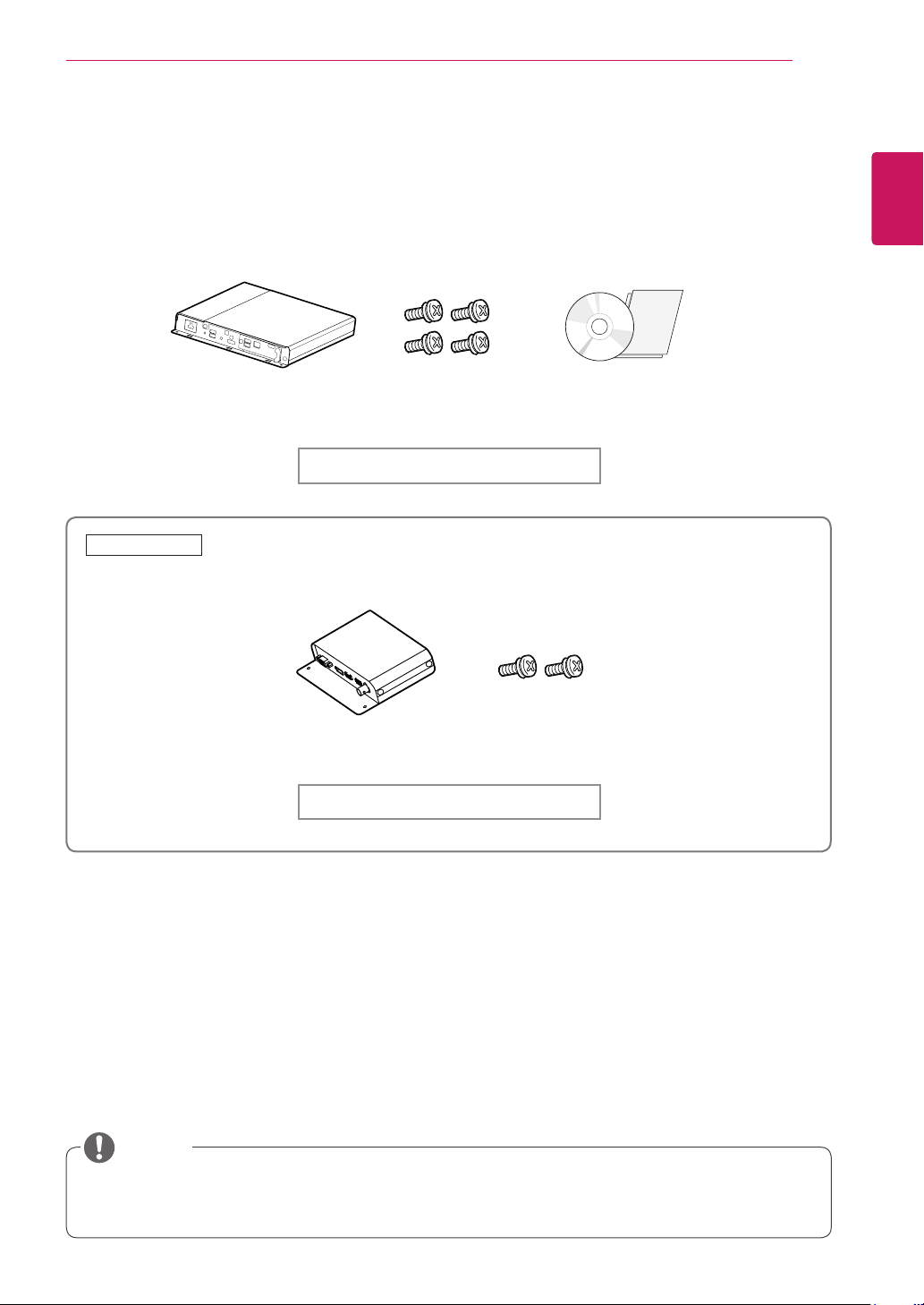
Optional Accessories
Without prior notice, optional accessories are subject to change to improve the performance of the product,
and new accessories may be added. The illustrations in this manual may differ from the actual product and
accessories.
Media Player
84WS70MS
Only supported for 84WS70MS.
Screws
Media Player Kit
CD(Owner's Manual)/ Card
ENGLISH
ENG
Optional Box
Screws
Optional Box Kit
NOTE
Optional accessories are not included for all models.
The Optional Box Port may be used for future devices. It is currently not supported.
ASSEMBLING AND PREPARING
6
ENGLISH
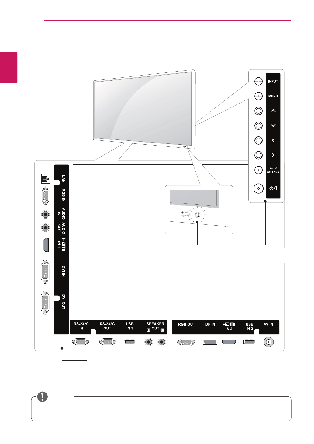
Parts and buttons
ENG
Connection panel
NOTE
You can set the Power indicator to on or off by selecting
IR Receiver/
Power Indicator
Lighting On: Turned on
Lighting Off: Turned off
OPTION
in the main menu.
Screen Buttons/
Screen Marks

ASSEMBLING AND PREPARING
Screen Marks Description
INPUT Changes the input source.
MENU Accesses the main menus, or saves your input and exits the menus.
Moves the selection up and down.
Adjusts the volume level.
AUTO/SET Displays the current signal and mode.
I
/
IR Receiver This is where the unit receives signals from the remote control.
Power Indicator This Indicator lights up red when the display operates normally(on mode). If the display
Press this button to adjust the screen automatically (available only in RGB mode)
Turns the power on or off.
In sleep mode (In Power Saving mode), this indicator color changes to amber.
7
ENGLISH
ENG
ASSEMBLING AND PREPARING
8
ENGLISH
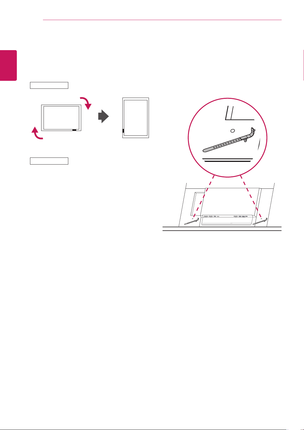
Portrait Layout
ENG
When installing in a Portrait Layout, rotate the
monitor clockwise 90 degrees (when facing the
screen).
Installing in Portrait Position is not supported.
84WS70MS
84WS70BS
Using the Mounting Cable Tie
Insert the two cable ties into the bottom hole on the
back of the set as shown in the figure to organize
cables.
ASSEMBLING AND PREPARING
9
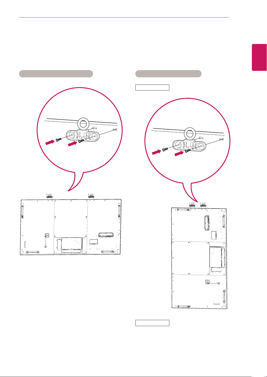
Connecting the Eye-Bolt Bracket
The Eye-bolt bracket is designed to be used to lift the set up.
Attach the bracket to the product using the two screws provided.
Installing in Landscape Position Installing in Portrait Position
84WS70MS
ENGLISH
ENG
84WS70BS
Installing in Portrait Position is not supported.
10
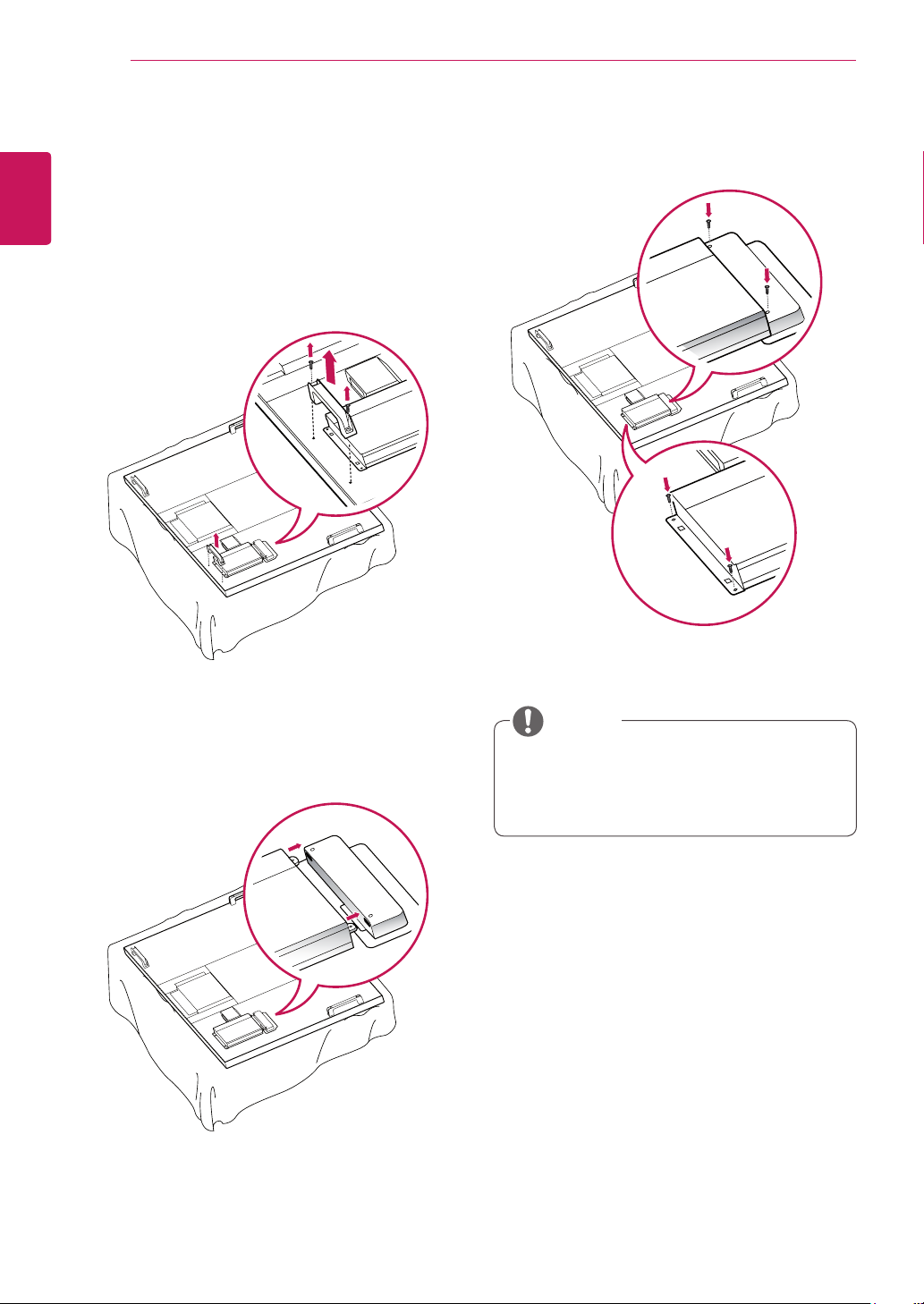
Connecting the Media
ENGLISH
ENG
Player
1
ASSEMBLING AND PREPARING
Place a soft cloth on the table and put the set
with the screen facing downward. Remove the
handle at the bottom of the section where the
Media Player is mounted on the set.
Attach the Media Player using the four provided
3
screws.
To mount the Media Player, push it into the
2
special compartment located on the back of the
monitor.
NOTE
Use the screws provided with the product
(diameter 3.0 mm x pitch 0.5 mm x length 6.0
mm).
ASSEMBLING AND PREPARING
11
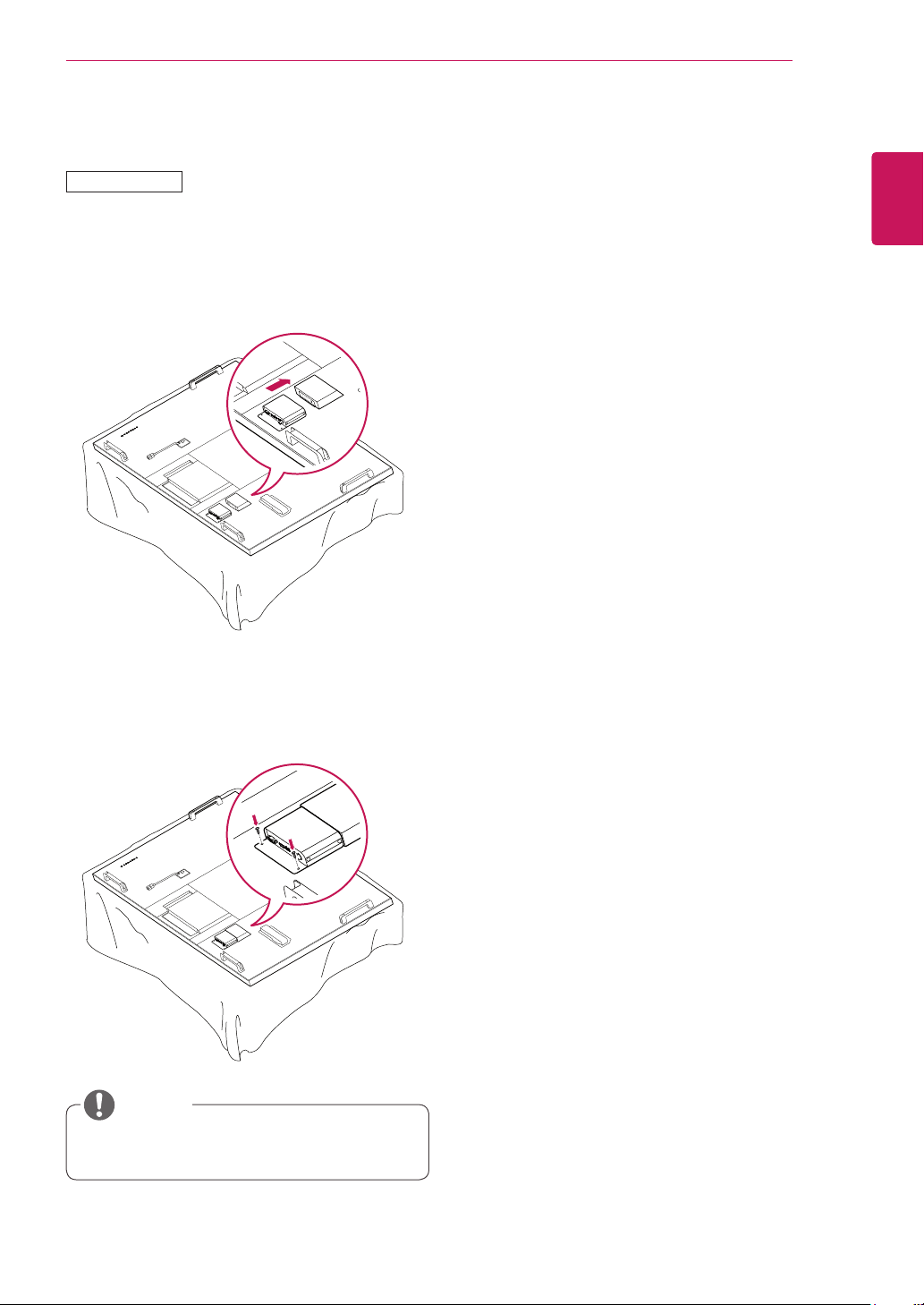
Connecting an Optional Box
84WS70MS
Place a soft cloth on the table and put the set
1
with the screen facing downward. To mount
the box, push it into the special compartment
located on the back of the monitor.
ENGLISH
ENG
Attach the box using the two provided screws.
2
NOTE
Only supported for 84WS70MS.
ASSEMBLING AND PREPARING
12
ENGLISH
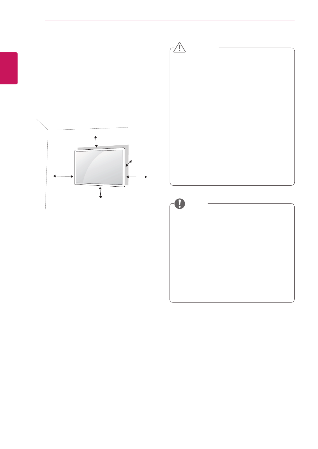
Mounting on a wall
ENG
For proper ventilation, allow a clearance of 10
cm on each side and from the wall. Detailed
installation instructions are available from your
dealer, see the optional Tilt Wall Mounting Bracket
Installation and Setup Guide.
If you intend to mount the Monitor to a wall, attach
a Wall mounting interface (optional parts) to the
back of the set.
When you install the Monitor using a wall mounting
interface (optional parts), attach it carefully so it
will not fall.
1
2
10 cm
10 cm
10 cm
10 cm
Please, use a wall mount and screws in
accordance with VESA Standards.
If you use screws longer than standard, the
monitor might be damaged internally.
10 cm
CAUTION
Disconnect the power before installing or
moving the monitor. Otherwise electric shock
may occur.
If you install the Monitor on a ceiling or
slanted wall, it may fall and result in severe
injury. Use an authorized LG wall mount
and contact the local dealer or qualified
personnel.
Do not over tighten the screws as this may
cause damage to the Monitor and void your
warranty.
Use screws and wall mounts that meet the
VESA standard. Any damages or injuries by
misuse or using an improper accessory are
not covered by the warranty.
NOTE
The wall mount kit includes an installation
manual and necessary parts.
The wall mount bracket is optional. You can
obtain additional accessories from your local
dealer.
The length of screws may differ depending
on the wall mount. Be sure to use the proper
length.
For more information, refer to the instructions
supplied with the wall mount.
If you use improper screws, the product might
3
be damaged and drop from mounted position.
In this case, LG Electronics is not responsible
for damage.
Please use VESA standard as below.
4
785mm or greater
* Fastening screw: Diameter 8.0 mm x Pitch
1.25 mm x Length 16 mm
ASSEMBLING AND PREPARING
13
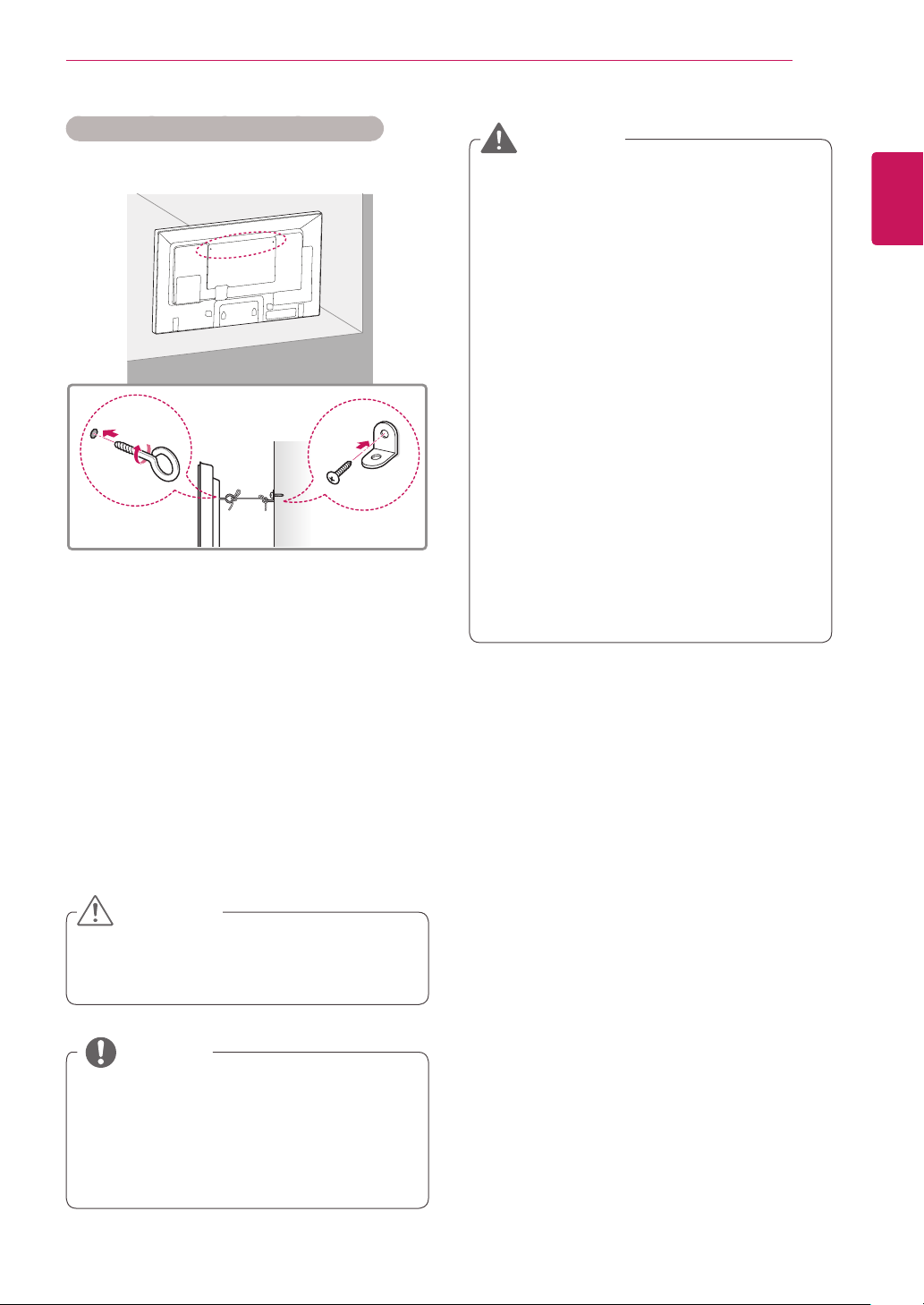
Securing the product to a wall (optional)
(Depending on model)
Insert and tighten the eye-bolts, or product
1
brackets and bolts on the back of the product.
- If there are bolts inserted at the eye-bolts
position, remove the bolts first.
WARNING
If a product is not positioned in a sufficiently
stable location, it can be potentially
hazardous due to falling. Many injuries,
particularly to children, can be avoided by
taking simple precautions such as:
»Using cabinets or stands recommended
by the manufacturer of the product.
»Only using furniture that can safely
support the product.
»Ensuring the product is not overhanging
the edge of the supporting furniture.
»Not placing the product on tall furniture
(for example, cupboards or bookcases)
without anchoring both the furniture and
the product to a suitable support.
»Not standing the product on cloth or other
materials placed between the product
and supporting furniture.
»Educating children about the dangers of
climbing on furniture to reach the product
or its controls.
ENGLISH
ENG
Mount the wall brackets with the bolts to the
2
wall.
Match the location of the wall bracket and the
eye-bolts on the rear of the product.
Connect the eye-bolts and wall brackets tightly
3
with a sturdy rope.
Make sure to keep the rope horizontal with the
flat surface.
CAUTION
Make sure that children do not climb on or
hang on the product.
NOTE
Use a platform or cabinet that is strong and
large enough to support the product securely.
Brackets, bolts and ropes are optional. You
can obtain additional accessories from your
local dealer.
REMOTE CONTROL
P
A
G
E
INPUT
ENERGY
SAVING
MARK
ARC
ON
OFF
. , !
ABCDEF
GHI
JKL
MNO
PQRSTUV
1/a/A
- * #
WXYZ
CLEAR
S.MENU
MONITOR
PSM
AUTO
MUTE
BRIGHT
NESS
MENU
POWER
14
ENGLISH
REMOTE CONTROL
ENG
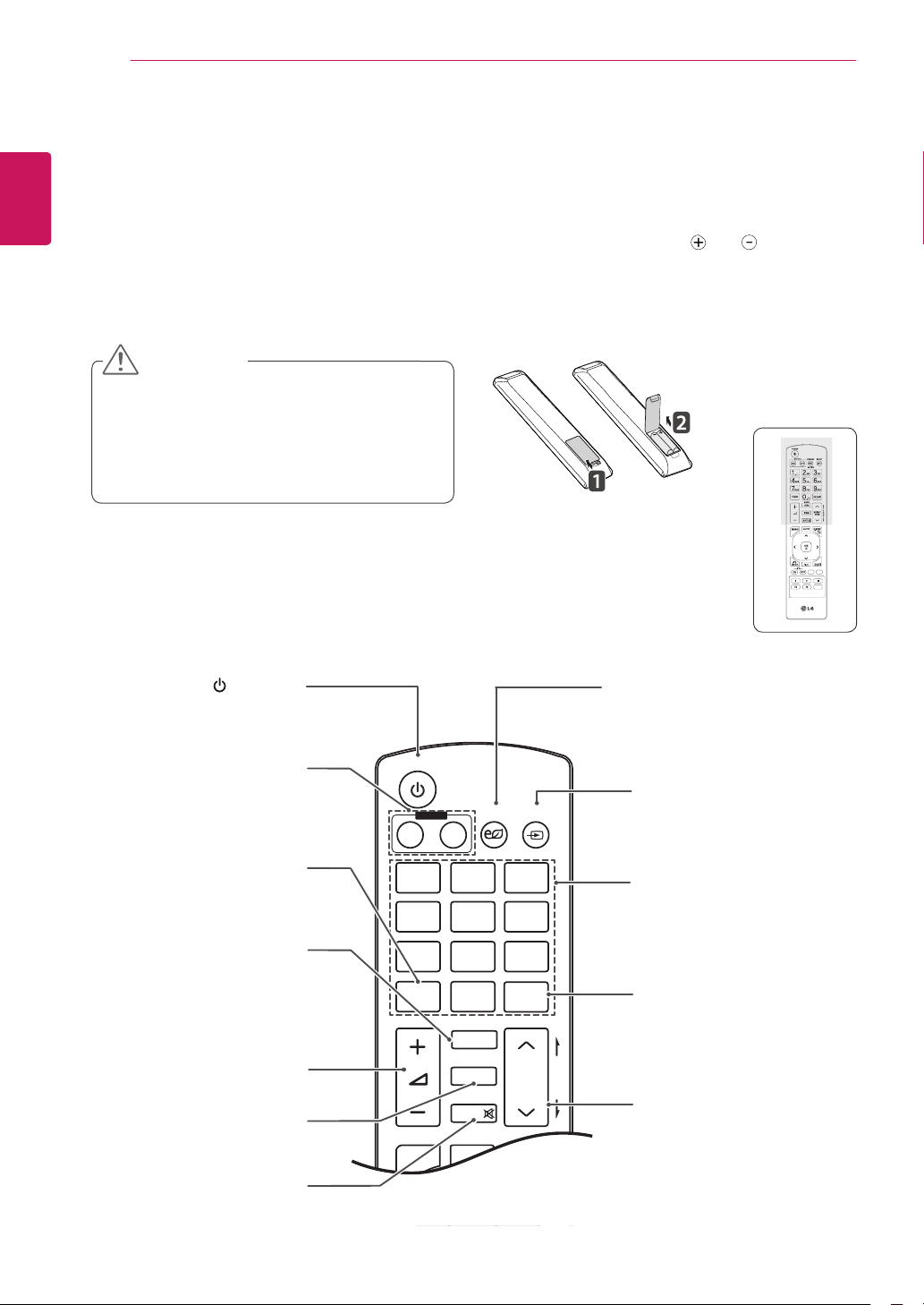
The descriptions in this manual are based on the buttons of the remote control. Please read this manual
carefully and use the Monitor correctly.
To replace batteries, open the battery cover, replace batteries (1.5 V AAA) matching and ends to the
label inside the compartment, and close the battery cover.
To remove the batteries, perform the installation actions in reverse.
CAUTION
Do not mix old and new batteries, as this
may damage the remote control.
Make sure to point the remote control at the
remote control sensor on the Monitor.
Turns the Monitor on or off.
MONITOR ON / OFF
Turn off the monitor and then
turn it back on.
1/a/A Button
Toggles between numerical
Selects the Aspect Ratio
The current model does not
Adjusts the volume level.
Selects the Picture Status
and alphabetical.
support this function.
Volume Up / Down
Mutes all sounds.
(POWER)
ARC
Mode.
MARK
PSM
Mode.
MUTE
ENERGY SAVING
Adjusts the brightness of
the screen to reduce energy
consumption.
INPUT
Selects the input mode.
Number and Alphabet buttons
Enters numerical or alphabetical
characters depending on the
setting.
CLEAR
Deletes the entered numerical
or alphabetical character.
BRIGHTNESS Key
Adjust the brightness by
pressing the Up and Down
buttons on the remote control.
REMOTE CONTROL
P
A
G
E
INPUT
ENERGY
SAVING
MARK
ARC
ON
OFF
. , !
ABCDEF
GHI
JKL
MNO
PQRSTUV
1/a/A
- * #
WXYZ
CLEAR
OK
S.MENU
MONITOR
PSM
AUTO
MUTE
BRIGHT
NESS
MENU
ID
BACK
TILE
ON
OFF
EXIT
POWER
15
ENGLISH
ENG
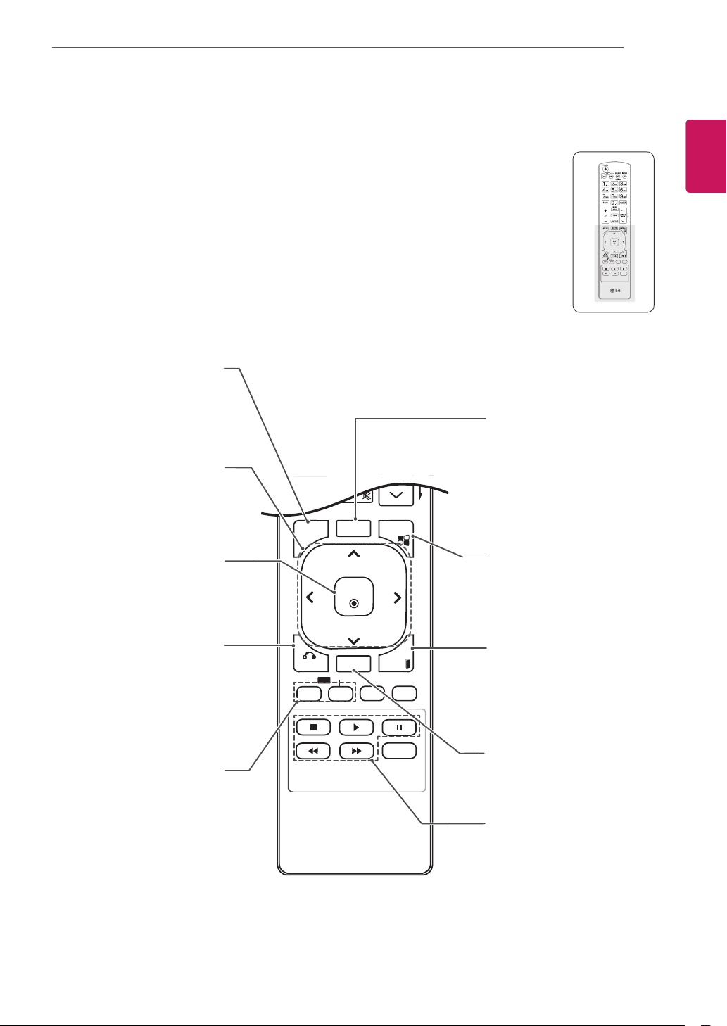
MENU
Accesses or exits the menus.
Navigation buttons
Scrolls through menus or
options.
Selects menus or options and
Allows the user to move back
confirms your input.
one step.
ID ON/OFF
The current model does not
support this function.
OK
BACK
AUTO
Automatically adjusts picture
position and minimizes image
instability.(RGB input only)
S.MENU
(SuperSign Menu Key)
Selects the SuperSign OSD
Menu.(SuperSign input only)
EXIT
Clears all on-screen displays
and returns to Monitor
viewing from any menu.
TILE
The current model does not
support this function.
USB Menu control buttons
Controls media playback.
REMOTE CONTROL
INPUT
ENERGY
SAVING
ON
OFF
. , !
ABCDEF
GHI
JKLMNO
MONITOR
POWER
INPUT
ENERGY
SAVING
ON
OFF
. , !
ABCDEF
GHI
JKLMNO
MONITOR
POWER
OK
S.MENU
AUTO
MENU
OK
S.MENU
AUTO
MENU
16
ENGLISH
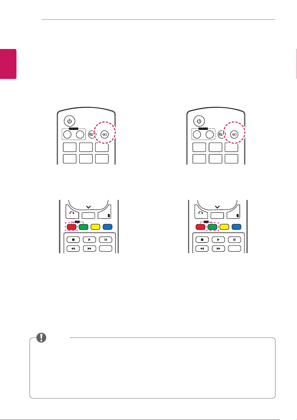
Change Device Name
ENG
You can edit the name of the external device connected to the input port to display which device is
connected to the port.
1 Press INPUT to access Input List. 1 Press INPUT to access Input List.
2 In the Input List screen, press the ID ON (red)
on the remote control.
SimpLink Setting
SimpLink allows you to control various multimedia
devices to enjoy the multimedia simply by using
the remote control through the SimpLink menu.
2 In the Input List screen, press the ID OFF
(green) on the remote control.
BACK
ON
ID
OFF
TILE
EXIT
3 You can select any option for Input Label
except USB.
NOTE
AV, RGB, HDMI1, HDMI2, DVI-D, Display Port
Blu-ray, DVD, VCR, Home theater, AV Receiver, Set-top Box, Cable Box,
is displayed on the
External inputs supported:
Input labels available:
Satellite, IPTV, TV, Smart Box, Game, PC, Notebook, Smart phone, Camera,
The set
If DTV/PC compatible signals are output, the screen settings change according to the
setting. If Input Label is set to PC, the screen's aspect ratio is automatically set to Just Scan.
Input Label
Input List
BACK
TILE
ID
OFF
ON
and
, or when switching the input.
EXIT
SuperSign
Camcorder.
and
Input Label
USING THE MONITOR
17
USING THE MONITOR
Connecting to a PC
Your Monitor supports the Plug & Play* feature.
* Plug & Play: This is the function that allows a PC
to use the monitor without installing a driver.
NOTE
It is recommended you use an HDMI
connection for the best image quality.
Use a shielded signal interface cable, such
as D-sub 15 pin signal cable and DVI cable,
with a ferrite core to maintain standard
compliance for the product.
If you turn the Monitor on when the set is
cold, the screen may flicker. This is normal.
Some red, green, or blue spots may appear
on the screen. This is normal.
For some graphic cards, the screen may not
display properly when you use dual monitors.
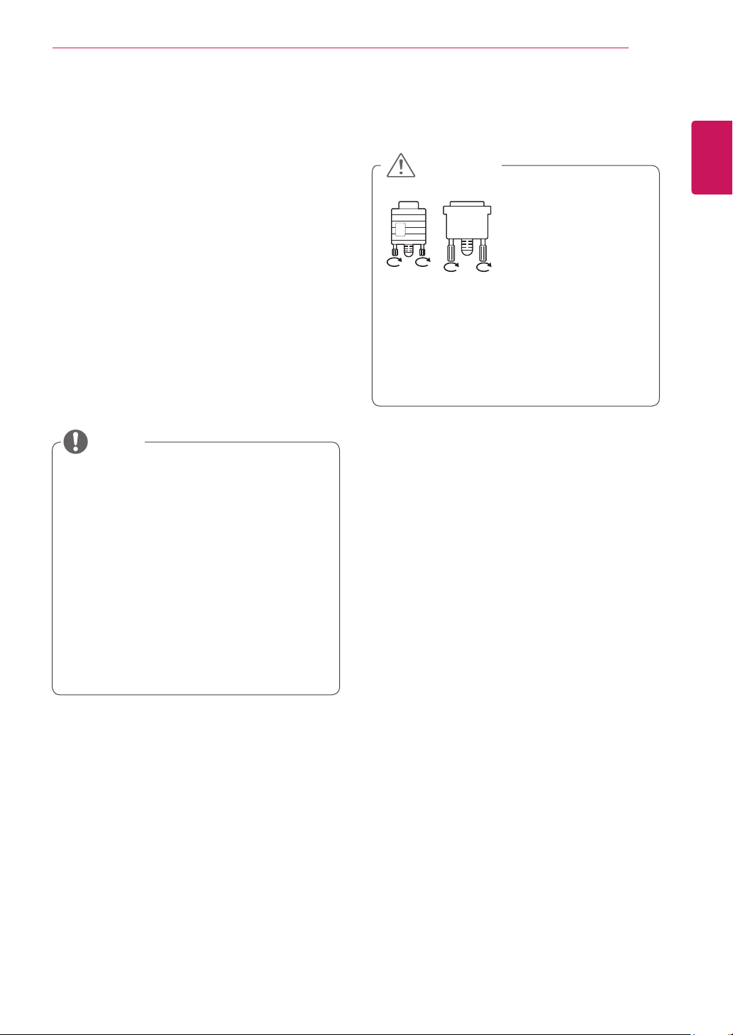
CAUTION
Connect the
signal input cable
and tighten it by
turning the screws
clockwise.
Do not press the screen with your finger for
a long time as this may result in temporary
distortion on the screen.
Avoid displaying a fixed image on the screen
for a long period of time to prevent image
burn. Use a screensaver if possible.
ENGLISH
ENG
USING THE MONITOR
18
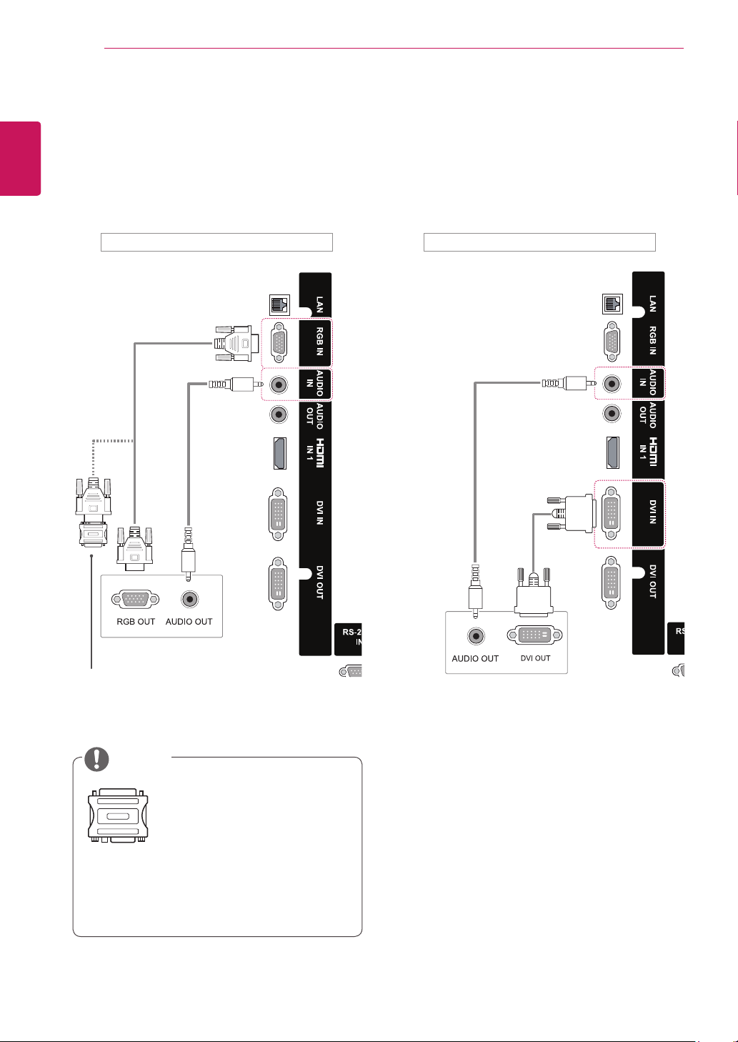
RGB connection
ENGLISH
ENG
Transmits an analog video signal from your PC to
the Monitor. Connect the PC and the Monitor
set with the 15 pin signal cable as shown in the
following illustrations.
Select RGB input source on the monitor.
DVI-D connection
Transmits a digital video signal from your PC to
the Monitor. Connect the PC and the Monitor
with a DVI cable as shown the following
illustrations.
Select DVI-D input source on the monitor.
Back of the product. Back of the product.
(not included)
(not
included)
(not
included)
(not included)
PC/ MAC
Macintosh Adapter
(not included)
NOTE
Use the standard Macintosh
adapter since an incompatible
adapter is available in the
market. (Different signaling
system)
Apple computers may require an adapter to
connect to this monitor. Call or visit their web
site for more information.
PC
USING THE MONITOR
19
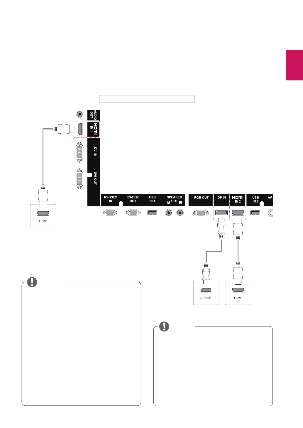
HDMI connection
Transmits the digital video and audio signals
from your PC to the Monitor. Connect the PC and
the Monitor with an HDMI cable as shown in the
following illustration.
Select HDMI input source.
Back of the product.
(not
included)
Display Port connection
Transmits the digital video and audio signals from
your PC to the Monitor. Connect the PC and the
Monitor with a Display Port cable as shown in the
following illustrations.
Select Display Port input source.
ENGLISH
ENG
PC
NOTE
Use a High Speed HDMI®/™ Cable.
Please check the PC environment if you
cannot hear the sound in HDMI mode. Some
PCs require you to manually change the
default audio output to HDMI.
If you want to use HDMI-PC mode, you must
set the input label to PC mode.
When HDMI PC is used, a compatiblity
problem could occur.
Use a certified cable with the HDMI logo
attached. If you do not use a certified HDMI
cable, the screen may not display or a
connection error may occur.
Recommended HDMI cable types
-High-Speed HDMI®/™ Cable
-High-Speed HDMI®/™ Cable with Ethernet
(not included)
PC
NOTE
It is recommended to use the following
specifications to play 3840 x 2160 video
seamlessly in HDMI or DP modes.
»Recommended PC specifications - CPU:
Intel core i7 or higher, graphic card: NVIDIA
GTX TITAN or higher, AMD HD7000 series
or higher.
»Recommended video - For H.264, 140
Mbps or lower data transmission rate.
20
INPUT
ENERGY
SAVING
ON
OFF
. , !
ABCDEF
GHI
JKLMNO
MONITOR
POWER
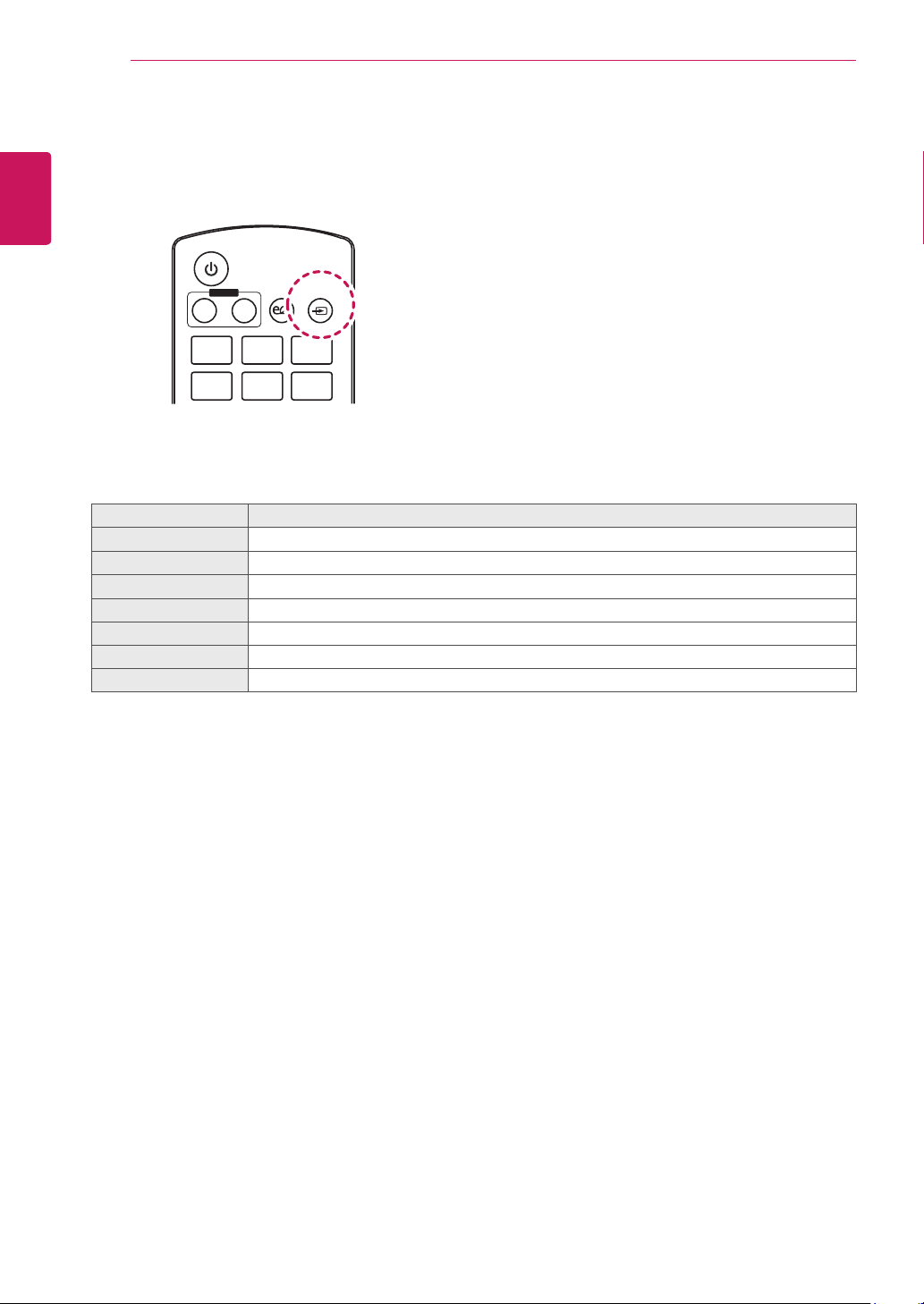
Using the Input List
ENGLISH
ENG
1
2
USING THE MONITOR
Press
INPUT
to access the
INPUT LIST
.
Press the Navigation buttons to scroll to one of the input sources and press OK.
Input source Description
AV
RGB
HDMI1
HDMI2
Display Port
DVI-D
SuperSign
Watch video from a VCR or other external devices.
View a PC display on the screen.
Watch contents in a PC, DVD of Digital set-top box other high definition devices.
Watch contents in a PC, DVD of Digital set-top box other high definition devices.
Watch contents in a PC, DVD of Digital set-top box other high definition devices.
View a PC display on the screen.
Views the Media Player display on the screen.
ENTERTAINMENT
21
ENTERTAINMENT
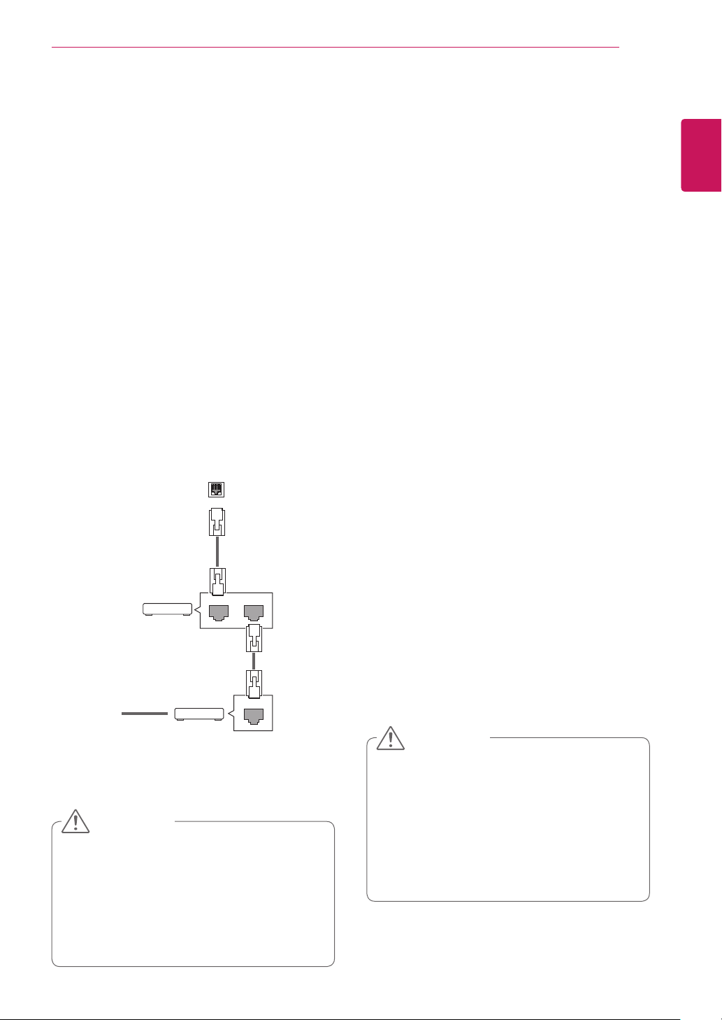
Connecting to a wired network
(Depending on model)
Connect the display to a local area network (LAN)
via the LAN port as shown in the following illustration and set up the network settings.
This monitor only supports a wired network connection.
After making a physical connection, a small
number of home networks may require the display
network settings to be adjusted. For most home
networks, the display will connect to automatically
without any adjustments.
For detail information, contact your internet provider or router manual.
LAN
ENGLISH
ENG
Follow the steps below to set up the network settings. (Even if your display is already connected
automatically, running setup again will not harm
anything.)
1 Press MENU to access the main menus.
2 Press the Navigation buttons to scroll to NET-
WORK and press OK.
3 Press the Navigation buttons to scroll to Net-
work Connection and press OK.
4 Select Set Expert.
5 Select IP Auto Setting or IP Manual Setting.
- IP Manual Setting : press the navigation and
number buttons. IP addresses will need to be
input manually.
- IP Auto Setting : Select this if there is a
DHCP server (Router) on the local area network (LAN) via wired connection, the display
will automatically be allocated an IP address.
If you’re using a broadband router or broadband modem that has a DHCP (Dynamic
Host Configuration Protocol) server function.
The IP address will automatically be determined.
@
Internet
Internet
Router
Cable modem
LANWAN
ETHERNET
CAUTION
Do not connect a modular phone cable to the
LAN port.
Since there are various connection meth-
ods, please follow the specifications of your
telecommunication carrier or internet service
provider.
6 When you are finished, press EXIT.
CAUTION
Network setting menu will not be available
until the display is connected to physical
network.
Since there are various connection meth-
ods, please follow the specifications of your
telecommunication carrier or internet service
provider.

ENTERTAINMENT
22
ENGLISH
ENG
NOTE
If you want to access the Internet directly on
your display, the internet connection should
always be on.
If you cannot access the Internet, check
the network conditions from a PC on your
network.
When you use Network Setting, check the
LAN cable or check if DHCP in the router is
turned on.
If you do not complete the network settings,
the network may not work properly.
Tips for Network setting
Use a standard LAN cable with this display. Cat5
or better with a RJ45 connector.
Many network connection problems during set
up can often be fixed by re-setting the router
or modem. After connecting the display to the
home network, quickly power off and/or disconnect the power cable of the home network router
or cable modem. Then power on and/or connect
the power cable again.
Depending on the internet service provider
(ISP), the number of devices that can receive
internet service may be limited by the applicable
terms of service. For details, contact your ISP.
LG is not responsible for any malfunction of the
display and/or the internet connection feature
due to communication errors/malfunctions associated with your internet connection, or other
connected equipment.
LG is not responsible for problems within your
internet connection.
You may experience undesired results if the
network connection speed does not meet the
requirements of the content being accessed.
Some internet connection operations may not
be possible due to certain restrictions set by the
Internet service provider (ISP) supplying your
Internet connection.
Any fees charged by an ISP including, without
limitation, connection charges are your responsibility.
A 10 Base-T or 100 Base-TX LAN port is
required when using a wired connection to this
display. If your internet service does not allow for
such a connection, you will not be able to connect the display.
A DSL modem is required to use DSL service
and a cable modem is required to use cable
modem service. Depending on the access
method of and subscriber agreement with your
ISP, you may not be able to use the internet
connection feature contained in this display or
you may be limited to the number of devices you
can connect at the same time. (If your ISP limits
sub-scription to one device, this display may
not be allowed to connect when a PC is already
connected.)
The use of a “Router” may not be allowed or its
usage may be limited depending on the policies
and restrictions of your ISP. For details, contact
your ISP directly.
Network Status
1 Press MENU to access the main menus.
2 Press the Navigation buttons to scroll to NET-
WORK and press OK.
3 Press the Navigation buttons to select Net-
work Status.
4 Press OK to check the network status.
5 When you are finished, press EXIT.
 Loading...