

LG 60PM4M - - 60"" Plasma Panel, 42PM4M, 50PM4M Owner's Manual

LAS
0 ITO
MODELS: 42PM4M
50PM4M
60PM4M
OWNER'S MANUAL
P_ease read this manua_ carefully before operating your set.
Retain it for future reference.
Record model number and seria_ number of the set.
See the label attached on the back cover and quote
this information to your dealer
when you require service.
P/NO: 38289U0558J (0711-REV00)
Printed in Korea

Safety Instructions
m_
r hi, n
f
WARNING/CAUTION
WARNING:
TO REDUCE THE RISK OF ELECTRIC SHOCK DO NOT REMOVE COVER (OR BACK). NO USER
SERVICEABLE PARTS INSIDE. REFER TO QUALIFIED SERVICE PERSONNEL.
The lightning flash with arrowhead symbol, within an equilateral triangle, is intended to alert the user to
the presence of uninsulated "dangerous voltage" within the product's enclosure that may be of suffi-
cient magnitude to constitute a risk of electric shock to persons.
The exclamation point within an equilateral triangle is intended to alert the user to the presence of
important operating and maintenance (servicing) instructions in the literature accompanying the appli-
ance.
WARNING:
TO PREVENT FIRE OR SHOCK HAZARDS, DO NOT EXPOSE THIS PRODUCT TO RAIN OR MOISTURE.
FCC NOTICE
A Class B digital device
This equipment has been tested and found to comply with the limits for a Class B digital device, pursuant to Part
15 of the FCC Rules. These limits are designed to provide reasonable protection against harmful interference in
a residential installation. This equipment generates, uses and can radiate radio frequency energy and, if not
installed and used in accordance with the instructions, may cause harmful interference to radio communications.
However, there is no guarantee that interference will not occur in a particular installation. If this equipment does
cause harmful interference to radio or television reception, which can be determined by turning the equipment off
and on, the user is encouraged to try to correct the interference by one or more of the following measures:
- Reorient or relocate the receiving antenna.
- Increase the separation between the equipment and receiver.
- Connect the equipment into an outlet on a circuit different from that to which the receiver is connected.
- Consult the dealer or an experienced radiofTV technician for help.
• Any changes or modifications not expressly approved by the party responsible for compli=
ance could void the user's warranty.
CAUTION:
Do not attempt to modify this product in any way without written authorization from LG Electronics. Unauthorized mod-
ification could void the user's warranty.
COMPLIANCE:
The responsible party for this product's compliance is:
LG Electronics U.S.A., Inc
1000 Sylvan Avenue, Englewood Cliffs, NJ 07632
1-800-243-0000
http://www.lgusa.com
2 Plasma Monitor

SafetyInstructions
f
IMPORTANT SAFETY INSTRUCTIONS
Important safety instructions shall be provided with each apparatus. This information shall be given in a separate booklet
or sheet, or be located before any operating instructions in an instruction for installation for use and supplied with the appa-
ratus.
This information shall be given in a language acceptable to the country where the apparatus is intended to be used.
The important safety instructions shall be entitled "Important Safety Instructions". The following safety instructions shall be
included where applicable, and, when used, shall be verbatim as follows. Additional safety information may be included by
adding statements after the end of the following safety instruction list. At the manufacturer's option, a picture or drawing that
illustrates the intent of a specific safety instruction may be placed immediately adjacent to that safety instruction :
1. Read these instructions.
2. Keep these instructions.
3. Heed all warnings.
4. Follow all instructions.
5. Do not use this apparatus near water,
6. Clean only with dry cloth.
8. Do not install near any heat sources such as radiators,
heat registers, stoves, or other apparatus (including ampli-
fiers)that produce heat.
9. Do not defeat the safety purpose of the polarized or
grounding-type plug. A polarized plug has two blades with
one wider than the other. A grounding type plug has two
blades and a third grounding prong, The wide blade or the
third prong are provided for your safety. If the provided plug
does not fit into your outlet, consult an electrician for replace-
ment of the obsolete outlet.
10. Protect the power cord from being walked on or pinched
particularly at plugs, convenience receptacles, and the point
where they exit from the apparatus.
7. Do not block any ventilation openings. Install in accor-
dance with the manufacturer's instructions.
wz_
11. Only use attachments/accessories specified by the man-
ufacturer.

Safety Instructions
f
12. Use only with the cart, stand, tripod, bracket, or table
specified by the manufacturer, or sold with the apparatus.
When a cart is used, use caution when moving the
cart!apparatus combination to avoid injury from tip-over.
PORTABLE CART WARNING
13. Unplug this apparatus during lightning storms or when
unused for long periods of time.
14. Refer all servicing to qualified service personnel.
Servicing is required when the apparatus has been dam-
aged in any way, such as power-supply cord or plug is dam-
aged, liquid has been spilled or objects have fallen into the
apparatus, the apparatus has exposed to rain or moisture,
does not operate normally, or has been dropped.
-..p
15. CAUTION concerning the Power Cord :
Most appliances recommend they be placed upon a dedi-
cated circuit; that is, a single outlet circuit which powers only
that appliance and has no additional outlets or branch cir-
cuits. Check the specification page of this owner's manual to
be certain.
Do not overload wall outlets. Overloaded wall outlets, loose
or damaged wall outlets, extension cords, frayed power
cords, or damaged or cracked wire insulation are dangerous.
Any of these conditions could result in electric shock or fire.
Periodically examine the cord of your
appliance, and if its appearance indicates damage or deteri-
oration, unplug it, discontinue use of the appliance, and have
the cord replaced with an exact replacement part by an
authorized servicer.
Protect the power cord from physical or mechanical abuse,
such as being twisted, kinked, pinched, closed in a door, or
walked upon. Pay particular attention to plugs, wall outlets,
and the point where the cord exits the appliance.
16. Outdoor Use Marking :
WARNING - To Reduce The Risk Of Fire Or Electric Shock,
Do Not Expose This Appliance To Rain Or Moisture.
17. Wet Location Marking :
Apparatus shall not be exposed to dripping or splashing and
no objects filled with liquids, such as vases, shall be placed
on the apparatus.
4 Plasma Monitor

Contents
Safety Instructions ............................. 2-4
Introduction
Accessories ............................ 7
Controls and Connection Options .......... 8-9
Remote Control Key Functions ............. 10
Installation
Installation Instructions ..................... 11
External Equipment Connections .......... 12-16
When Connecting to your PC ........... 12-13
Watching RGB Outputs ................... 13
When watching VCR / DVD ............... 14
When watching HDTV/DVD(480p/576p/
720p/1080i/480i/576i) ................... 15
When watching HDMI/DVI/RGB
from the VCR!DVD/Set-top Box
(480p/576p/720p/1080i) .................. 15
Watching AV Outputs .................... 16
Operation
Turning on the Monitor ..................... 17
Menu Language Selection .................. 17
Picture Menu Options
PSM (Picture Status Memory) .............. 18
Manual Picture Control (user option) ......... 18
CSM (Colour Status Memory) .............. 18
Manual Colour Temperature Control ......... 19
XD .................................. 19
Advanced - Cinema ..................... 20
Advanced - Black level ................... 20
Reset ................................ 20
Sound Menu Options
SSM ................................. 21
AVL (Auto Volume Leveler) ................ 21
Balance .............................. 22
Speaker .............................. 22
Timer Menu Options
Clock Setup ........................... 23
On/Off Time Setup ...................... 23
Auto sleep ............................ 24
Special Menu Options
Child Lock ............................ 25
ISM (Image Sticking Minimization) Method .... 25
Tile mode .......................... 26-27
Low Power ............................ 27
XD DEMO ............................ 28
Screen Menu Options
Auto Configure ......................... 29
Manual Configure ....................... 29
Selecting XGA mode ..................... 30
Setting the Picture Format ................ 30
Initializing (Reset to original factory settings) ...31
External Control Device Setup ............. 32-37
IR Code ................................ 38-39
Troubleshooting Checklist ................... 40
Product Specifications ....................... 41
After reading this manual, keep it handy for future reference.
Owner's Manual 5
Introduction
n
I
I 0 n
What is a Plasma Display Panel?
If voltage is applied to a gas within glass panels, ultraviolet rays are produced and fused with a fluorescent substance. At that
instant, light is emitted. A Plasma Display is the a next generation flat Display using this phenomenon.
160 ° - Wide angle range of vision
Your flat panel plasma screen offers an exceptionally broad viewing angle -- over 160 degrees. This means that the display is
clear and visible to viewers anywhere in the room.
Wide Screen
The screen of the Plasma Display is 42",50" or 60" so wide that your viewing experience is as if you are in a movie theater.
Versatile
The light weight and thin size makes it easy to install your plasma display in a variety of locations where conventional TVs would
not fit.
The Plasma Monitor Manufacturing Process: Why minute colored dots may be present on the Plasma
Monitor screen
The Plasma Display Panel which is the display device of this product is composed of 0.9 to 2.2 million cells. A few cell defects will
normally occur in the Plasma Monitor manufacturing process. Several minute colored dots visible on the screen should be accept-
able. This also occurs in other Plasma Monitor manufacturers' products and the tiny dots appearing does not mean that this
Plasma Monitor is defective. Thus a few cell defects are not sufficient cause for the Plasma Monitor to be exchanged or returned.
Our production technology is designed to minimize cell defects during the manufacture and operation of this product.
Cooling Fan Noise
In the same way that a fan is used in a PC computer to keep the CPU (Central Processing Unit) cool, the Plasma Monitor is
equipped with cooling fans to cool the Monitor and improve its reliability. Therefore, a certain level of noise could occur while the
fans are operating and cooling the Plasma Monitor.
The fan noise doesn't have any negative effect on the Plasma Monitor's efficiency or reliability. The noise from these fans is nor-
mal during the operation of this product. We hope you understand that a certain level of noise from the cooling fans is acceptable
and is not sufficient cause for the Plasma Monitor to be exchanged or returned.
WARNING
TO REDUCE THE RISK OF FIRE AND ELECTRIC SHOCK, DO NOT EXPOSE THIS PRODUCT TO
RAIN OR MOISTURE.
6 Plasma Monitor
Introduction
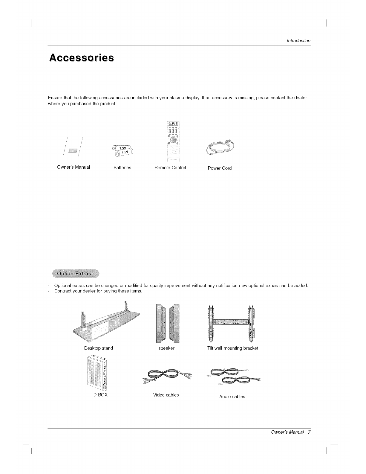
Ensure that the following accessories are included with your plasma display. If an accessory is missing, please contact the dealer
where you purchased the product.
/7
/
/
// //
,I
Owner's Manual Batteries Remote Control Power Cord
Optional extras can be changed or modified for quality improvement without any notification new optional extras can be added.
Contract your dealer for buying these items.
Desktop stand speaker
D-BOX Video cables
Tilt wall mounting bracket
Audio cables
Owner's Manual 7
Introduction
C0 ntroIS
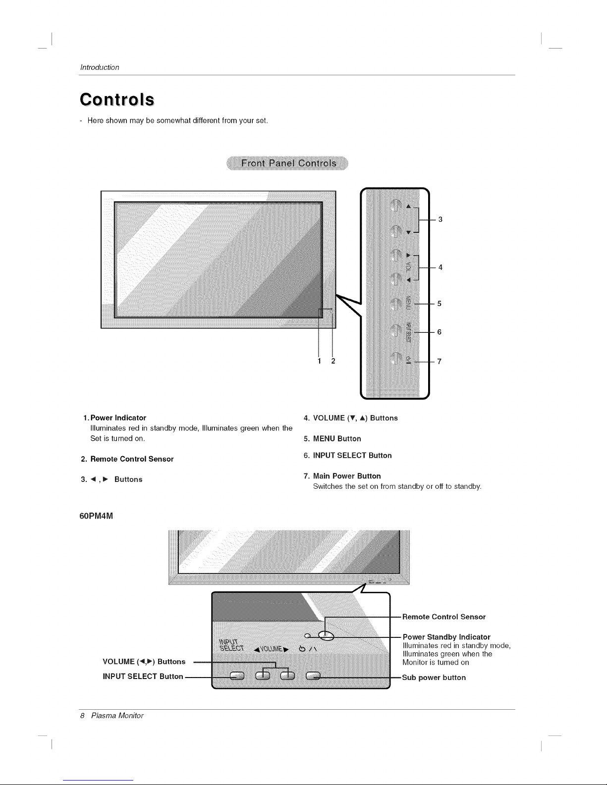
- Here shown may be somewhat different from your set.
1 2
1. Power Indicator
Illuminates red in standby mode, Illuminates green when the
Set is turned on.
2. Remote Control Sensor
3. ",_,_ Buttons
60PM4M
4. VOLUME (_', _,) Buttons
5. MENU Button
6. iNPUT SELECT Button
7. Main Power Button
Switches the set on from standby or off to standby.
Standby indicator
Illuminates red in standby mode,
Illuminates green when the
Monitor is turned on
power button
8 Plasma Monitor

Introduction
Connection Options
- Here shown may be somewhat different from your set.
1 2 3 4 5
1.
2.
3.
4.
5.
6.
REMOTE CONTROLIN
RS-232C INPUT(CONTROL&SERVICE) PORT
Connect to the RS-232C port on a PC.
HDMI/DVI IN
Connect a HDMI signal to this jack. Or connect a DVl(Video)
signal.
RGB INPUT
Connect the set output connector from a PC to the
appropriate input port.
RGB OUTPUT
You can watch the RGB signal on another set, connect RGB
OUTPUT to another set's PC input port.
AUDIO (RGB/DVI)
Connect the monitor output from a PC to the appropriate
input port.
COMPONENT INPUT 1-2
Connect a component video/audio device to these jacks.
7.
8.
9.
AV IN
S-VIDEO/AUDIO IN SOCKETS
Connect the S-VIDEO out socket of an VCR to the S-VIDEO
socket.
Connect the audio out sockets of the VCR to the audio sock-
ets as in AV.
AV OUT
EXTERNAL SPEAKER (8 ohm output)
Connect to optional external speaker(s).
* For further information, refer to 'Speaker & Speaker
Stand' manual.
POWER CORD SOCKET
This set operates on an AC power. The voltage is indicated on
the Specifications page. Never attempt to operate the set on
DC power.
Owner's Manual 9

Introduction
Remote Control Key Functions
When using the remote control, aim it at the remote control sensor on the monitor.
Under certain conditions such as if the remote IR signal is interrupted, the remote control may not function. Press
the key again as necessary.
AV buttons
Each time you press the Input but-
ton it will change to
AV -_ Component1
Component2_ RGB-_HDMI/DVI.
SLEEP
Sets the sleep timer.
PSM
Adjusts the factory preset picture
according to the room,
NUMBER buttons
There is not a function which issupported.
MENU
Displays on screen menus one by
one.
Exits the current menu.
Memorizes menu changes.
MUTE
Switches the sound on or off.
SLEEP PSM ARC AUTO
POWER
switches the set on from standby or off to
standby.
_INPUT
Selects the AV, Component, RGB or
HDMI modes.
switches the set on from standby.
_AUTO
Automatic adjustment function.
(Operational for the analog signal only)
_ARC
Changes the picture format.
_There is not a function which is supported.
_EXIT
Clears all on-screen displays and returns
to monitor viewing from any menu.
_SET
laccepts your selection or displays the
current mode.
l-I /_-
Volume Up/Down
11/v
IAdjusts menu settings.
M--Selects menu item.
--. : No function
Installing Batteries
• Open the battery compartment cover on the back side and install the bat-
teries matching correct polarity (+ with +, - with -).
• Install two 1.5V AAA batteries. Don't mix old or used batteries with new
ones. Replace cover.
10 Plasma Monitor

Installation
In= Ilation
Instal lation Instru ction s
• Install this monitor only in a location where adequate ventilation is available.
• If set is installed vertically, it is on the control key toward down.
GROUNDING
Ensure that you connect the grounding / earth wire to prevent possible
electric shock. If grounding methods are not possible, have a qualified
electrician install a separate circuit breaker. Do not try to ground the
unit by connecting it to telephone wires, lightening rods, or gas pipes.
Power
Supply
Short-circuit
Breaker
For proper ventilation, allow a clearance of 4" on each
side and 4" from the wall. Detailed installation instruc-
tions are available from your dealer, see the optional
Wall Mounting Bracke! Installation and Setup Guide.
For proper ventilation, allow a clearance of 4" on each
side and the top and 4" from the wall. Detailed installa-
tion instructions are included in the optional Desktop
Stand Installation and Setup Guide available from your
dealer.
Owner's Manual 11
Installation
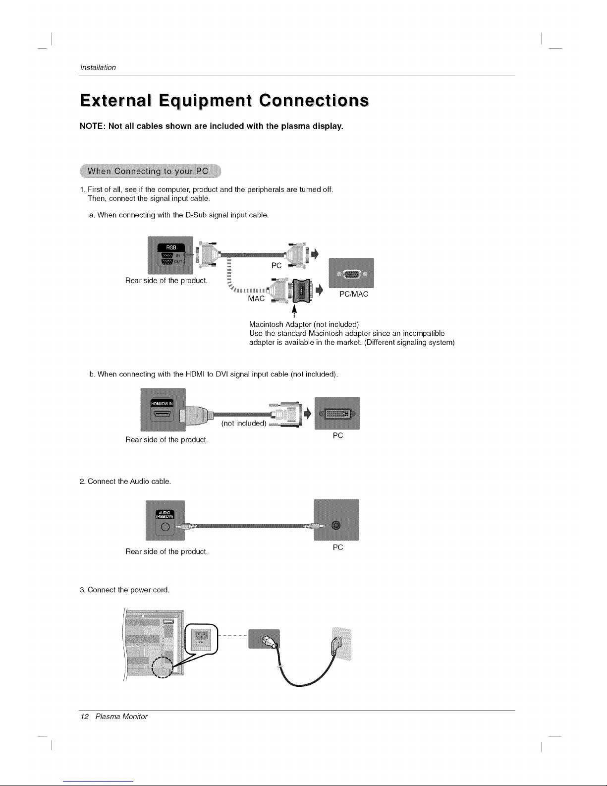
Equipment Connections
NOTE: Not all cables shown are included with the plasma display,
1. First of all, see if the computer, product and the peripherals are turned off.
Then, connect the signal input cable.
a. When connecting with the D-Sub signal input cable.
Rear side of the product.
PC/MAC
Macintosh Adapter (not included)
Use the standard Macintosh adapter since an incompatible
adapter is available in the market. (Different signaling system)
b. When connecting with the HDMI to DVI signal input cable (not included).
Rear side of the product.
2. Connect the Audio cable.
Rear side of the product.
3. Connect the power cord.
............................... j - _ _
PC
PC
12 Plasma Monitor
Installation
4. Turn on power by pressing the power button on the product.
Turn on the PC.
5. Select an input signal.
Press the INPUT button on the remote control to select the input
signal.
INPUT_ A /• _ SET
a. When connecting with a D-Sub signal input cable.
• Select RGB : 15-pin D-Sub analog signal.
b. When connecting with a HDMI to DVl signal input cable.
• Select HDMI/DVl : HDMI to DVl Digital signal.
NOTES: • How to connect to two computers.
Connect the signal cables (HDMI to DVI and D-Sub) to each computer.
Press the INPUT button on the remote control to select the computer to use.
• Directly connect to a grounded power outlet on the wall or a power bar with a ground wire.
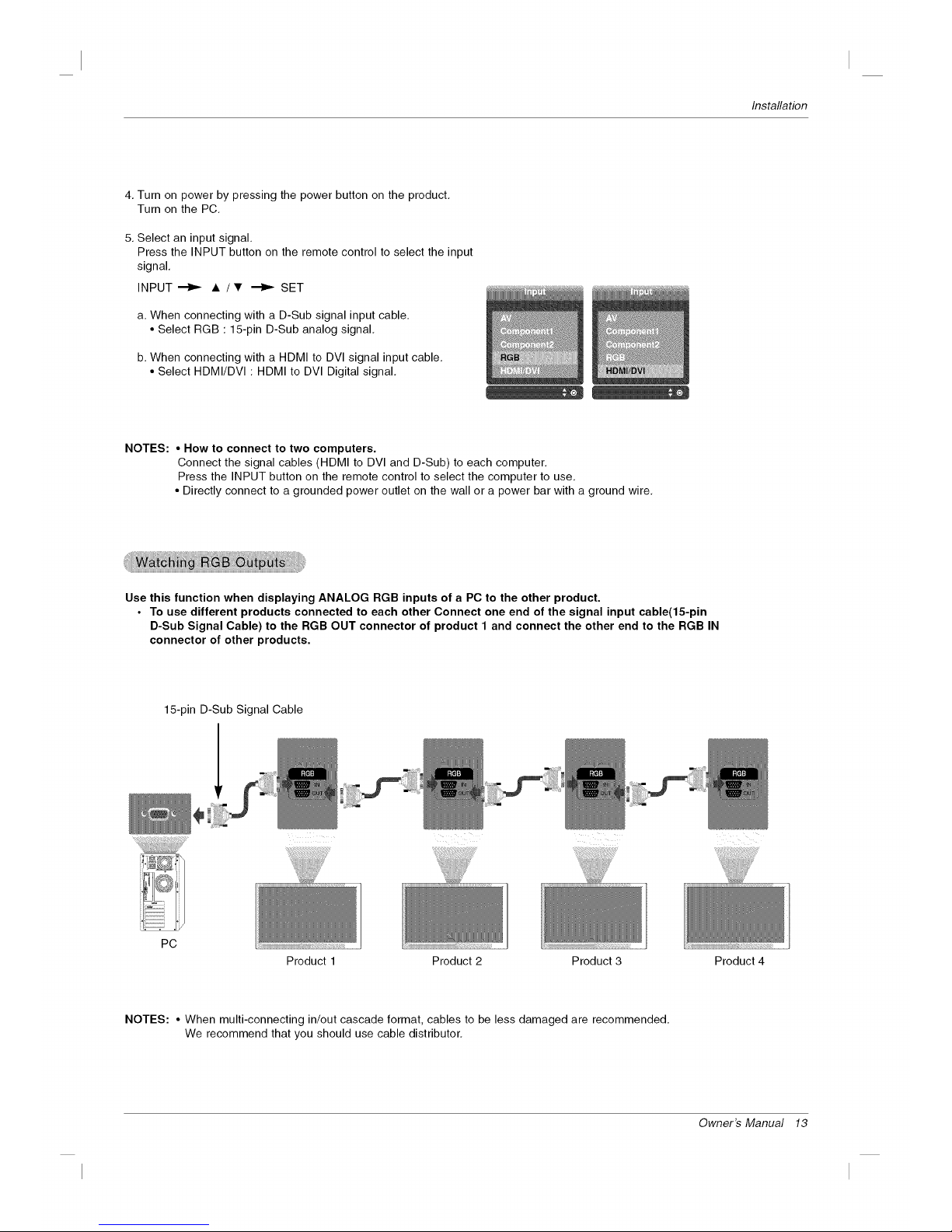
Use this function when displaying ANALOG RGB inputs of a PC to the other product.
• To use different products connected to each other Connect one end of the signal input cable(15-pin
D-Sub Signal Cable) to the RGB OUT connector of product 1 and connect the other end to the RGB IN
connector of other products.
15-pin D-Sub Signal Cable
PC
Product 1 Product 2 Product 3 Product 4
NOTES: • When multi-connecting in/out cascade format, cables to be less damaged are recommended.
We recommend that you should use cable distributor.
Owner's Manual 13
 Loading...