

LG 60PK550C Schematic

PLASMA TV
SERVICE MANUAL
CAUTION
BEFORE SERVICING THE CHASSIS,
READ THE SAFETY PRECAUTIONS IN THIS MANUAL.
CHASSIS : PP01A/B/C
MODEL : 60PK550C 60PK550C-TA
MODEL :
North/Latin America http://aic.lgservice.com
Europe/Africa http://eic.lgservice.com
Asia/Oceania http://biz.lgservice.com
Internal Use Only
P/NO : MFL62881419(1107-REV00)

- 2 -
LGE Internal Use OnlyCopyright ©2010 LG Electronics Inc. All rights reserved.
Only for training and service purposes
CONTENTS
CONTENTS ............................................................................................................................... 2
SAFETY PRECAUTIONS ...........................................................................................................3
SPECIFICATION.........................................................................................................................4
ADJUSTMENT INSTRUCTION ..................................................................................................7
BLOCK DIAGRAM .....................................................................................................................
9
EXPLODED VIEW ................................................................................................................. ..10
SVC. SHEET .............................................................................................................................
- 3 -
LGE Internal Use OnlyCopyright ©2010 LG Electronics Inc. All rights reserved.
Only for training and service purposes
SAFETY PRECAUTIONS
Many electrical and mechanical parts in this chassis have special safety-related characteristics. These parts are identified by in the
Schematic Diagram and Exploded View.
It is essential that these special safety parts should be replaced with the same components as recommended in this manual to prevent
X-RADIATION, Shock, Fire, or other Hazards.
Do not modify the original design without permission of manufacturer.
General Guidance
An isolation Transformer should always be used during the
servicing of a receiver whose chassis is not isolated from the AC
power line. Use a transformer of adequate power rating as this
protects the technician from accidents resulting in personal injury
from electrical shocks.
It will also protect the receiver and it's components from being
damaged by accidental shorts of the circuitry that may be
inadvertently introduced during the service operation.
If any fuse (or Fusible Resistor) in this monitor is blown, replace it
with the specified.
When replacing a high wattage resistor (Oxide Metal Film Resistor,
over 1W), keep the resistor 10mm away from PCB.
Keep wires away from high voltage or high temperature parts.
Due to high vacuum and large surface area of picture tube,
extreme care should be used in handling the Picture Tube.
Do not lift the Picture tube by it's Neck.
Leakage Current Cold Check(Antenna Cold Check)
With the instrument AC plug removed from AC source, connect an
electrical jumper across the two AC plug prongs. Place the AC
switch in the on position, connect one lead of ohm-meter to the AC
plug prongs tied together and touch other ohm-meter lead in turn to
each exposed metallic parts such as antenna terminals, phone
jacks, etc.
If the exposed metallic part has a return path to the chassis, the
measured resistance should be between 1MΩ and 5.2MΩ.
When the exposed metal has no return path to the chassis the
reading must be infinite.
An other abnormality exists that must be corrected before the
receiver is returned to the customer.
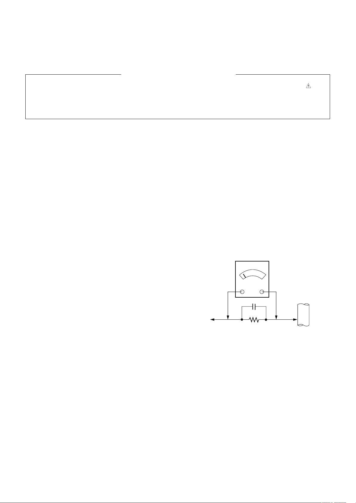
Leakage Current Hot Check (See below Figure)
Plug the AC cord directly into the AC outlet.
Do not use a line Isolation Transformer during this check.
Connect 1.5K/10watt resistor in parallel with a 0.15uF capacitor
between a known good earth ground (Water Pipe, Conduit, etc.)
and the exposed metallic parts.
Measure the AC voltage across the resistor using AC voltmeter
with 1000 ohms/volt or more sensitivity.
Reverse plug the AC cord into the AC outlet and repeat AC voltage
measurements for each exposed metallic part. Any voltage
measured must not exceed 0.75 volt RMS which is corresponds to
0.5mA.
In case any measurement is out of the limits specified, there is
possibility of shock hazard and the set must be checked and
repaired before it is returned to the customer.
Leakage Current Hot Check circuit
1.5 Kohm/10W
To Instrument's
exposed
METALLIC PARTS
Good Earth Ground
such as WATER PIPE,
CONDUIT etc.
AC Volt-meter
IMPORTANT SAFETY NOTICE
0.15uF
SPECIFICATION
NOTE : Specifications and others are subject to change without notice for improvement
V Application Range
.
This spec is applied to the PLASMA TV used H6 Chassis.
V Specification
Each part is tested as below without special appointment.
(1) Temperature : 25 °C ± 5 °C (77 °F ± 9 °F), CST : 40 ± 5
(2) Relative Humidity: 65 % ± 10 %
(3) Power Voltage: Standard Input voltage (100 V - 240 V ~, 50 / 60 Hz)
* Standard Voltage of each product is marked by models.
(4) Specification and performance of each parts are followed each drawing and specification by part number in accordance with
BOM.
(5) The receiver must be operated for about 20 minutes prior to the adjustment.
V Test Method
(1) Performance : LGE TV test method followed.
(2) Demanded other specification
Safety : CE, IEC specification
EMC : CE, IEC
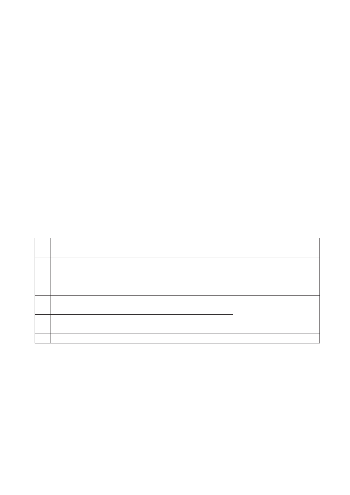
V Module Specification
(1) 60” HD
No Item Specification Remark60
Display Screen Device
1
Aspect Ratio
2
PDP Module
3
60 inch16:9 Color Display Module
16:9
PDP60R1####,
PDP
RGB Closed(Well) Type, Glass Filter(38 %)
Pixel Format: 1365 horiz. By 768 ver.
Operating Environment
4
Storage Environment
5
1) Temp. : 0 deg ~ 40 deg
2) Humidity : 20 % ~ 80 %
3) Temp. : -10 deg ~ 60 deg
LGE SPEC.
4) Humidity : 10 % ~ 90 %
Input Voltage
6
AC 100 V - 240 V ~, 50 / 60 Hz
Maker:SANKEN
Only for training and service purposes
- 4 -
LGE Internal Use OnlyCopyright ©2010 LG Electronics Inc. All rights reserved.
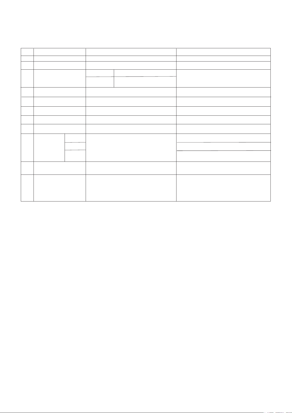
V Model General Specification
No Item Specification Remarks
1 Market EU
2 Broadcasting system PAL/SECAM-BG/I/DK
3
BANDAvailable Channel
VHF/UHF
CATV
PAL
C1~C69
S1~S47
SECAM-L spec out
4 Receiving system Analog : Upper Heterodyne
5 Scart Jack (2EA)
PAL
6 Video Input (1EA) PAL
7 Component Input (1EA) Y/Cb/Cr, Y/ Pb/Pr
8 RGB Input RGB-PC
9 HDMI Input
1EA
2EA
3 EA
Audio Input (5EA)
10
L/R Input(PC 1EA,SCART 2EA,
SIDE AV 1EA Component 1EA)
11 USB
SD Divx, MP3, JPEG
Full Scart 1EA, Half 1EA
Side 1EA(50/42PJ250R-ZA spec out)
50/42PJ250R-ZA spec out
Rear HDMI 1EA(50/42PJ250R-ZA only)
Rear HDMI 1EA , Side HDMI 1EA
Rear HDMI 2EA , Side HDMI 1EA
(50/42PK550R-ZA only)
42/50PJ250R-ZA, 42/50PK250R-ZA :
SVC Only 42/50PJ350R-ZA : only apply
for MP3, JPEG
( SD Divx Spec out )
Only for training and service purposes
- 5 -
LGE Internal Use OnlyCopyright ©2010 LG Electronics Inc. All rights reserved.
 Loading...