

LG 55LV75A-7B Instructions for quick setup

ENGLISH
ENG
Easy Setup Guide
LG Digital Signage
(MONITOR SIGNAGE)
Please read this manual carefully before operating your set and retain
it for future reference.
55LV75A
55LV77A
*MFL68606101*
www.lg.com
P/NO : MFL68606101(1510-REV02)
Printed in Korea
ASSEMBLING AND PREPARING
2
ENGLISH
ENG
ASSEMBLING AND PREPARING
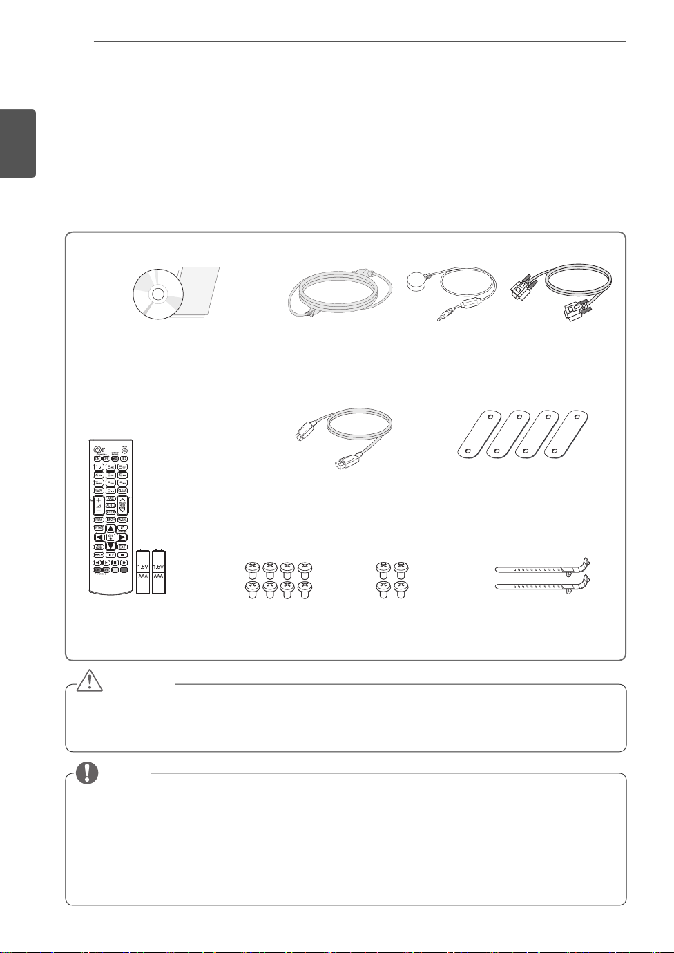
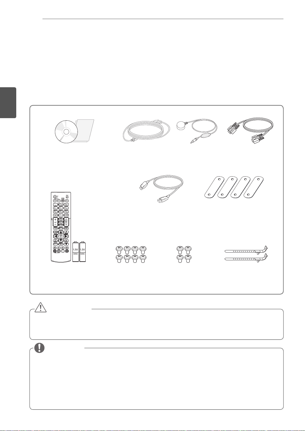
Accessories
Check your product box for the following items. If there are any missing accessories, contact the local
dealer where you purchased your product. The illustrations in this manual may differ from the actual product
and accessories.
CD (Owner's Manual) /
Cards
Power Cord IR Receiver RS-232C Cable
DP Cable
Tiling Guide(4 ea)
Remote Control
and Batteries
M4 x L6
Screws (8 ea)
M6 x L10
Screws (4 ea)
Mounting Cable Tie (2 ea)
(For Cable Arrangement)
CAUTION
Do not use any pirated items to ensure the safety and product life span.
Any damages or injuries by using pirated items are not covered by the warranty.
NOTE
The accessories supplied with your product may vary depending on the model.
Product specifications or contents in this manual may be changed without prior notice due to upgrade
of product functions.
SuperSign SW & Manual
- Downloading from the LG Electronics website.
- Visit the LG Electronics website (
latest software for your model.
https://www.lgecommercial.com/supersign
) and download the

ASSEMBLING AND PREPARING
3
Dimensions (Width x Height x Depth) / Weight
H
W
1213.4 mm x 684.2 mm x 88.5 mm / 23 kg
D
To View the Owner’s Manual
Insert CD-ROM in Computer.
CD-ROM will open automatically.(for Windows only)
If it does not run automatically, it is available to see the below sequence.
My computer
My computer
➙ Digital_LG(CD-ROM) ➙ Index.htm Open
➙ Digital_LG(CD-ROM) ➙ Manual ➙ Owner's Manual Open
ENGLISH
ENG
ASSEMBLING AND PREPARING
4
ENGLISH
ENG
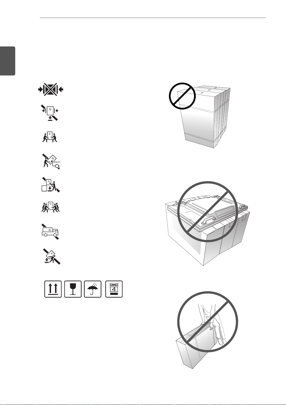
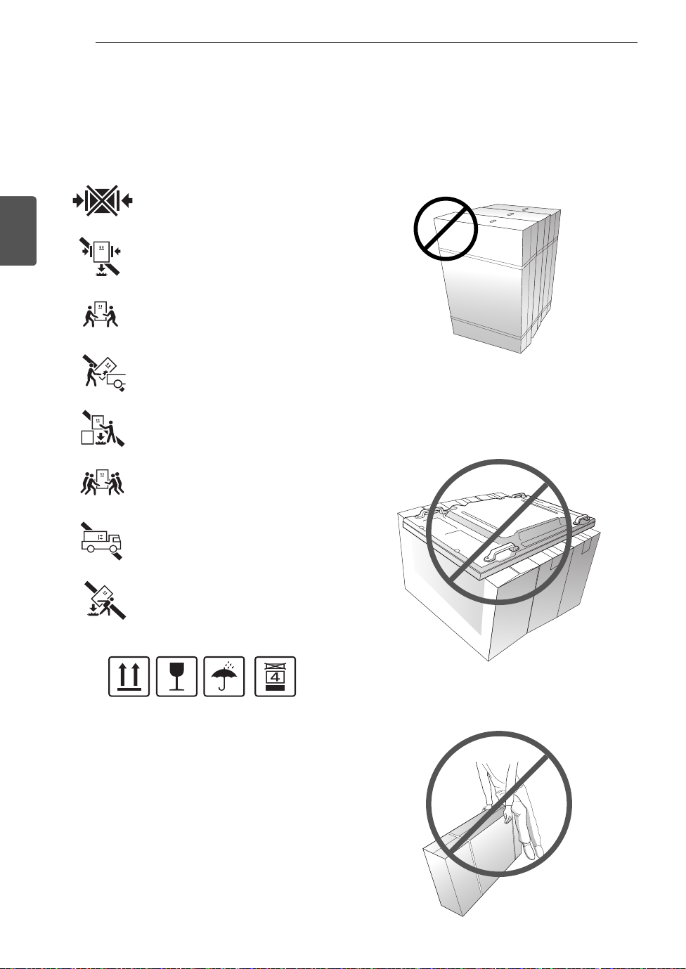
PRECAUTION IN MOVEMENT
- The illustration may look different from the actual product.
Adhere to the warning signs printed on the Box.
Do not Clamp
Do not drop from clamping.
2 Persons needed for transport
Load with care.
Do not drop from stacking.
4 Persons needed for transport
Do not tumble the Set box sideward down.
Do not place the product on the top of a box.
Do not transport horizontally.
Do not drop from carrying.
This way up/ Fragile/ Keep away from rain/ Stacking limit 4.
Do not lean on the product.
ASSEMBLING AND PREPARING
5
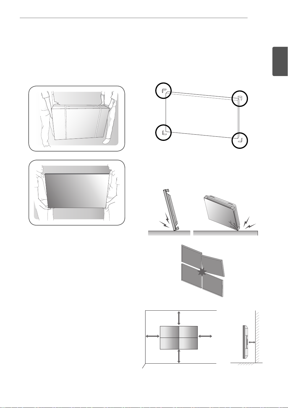
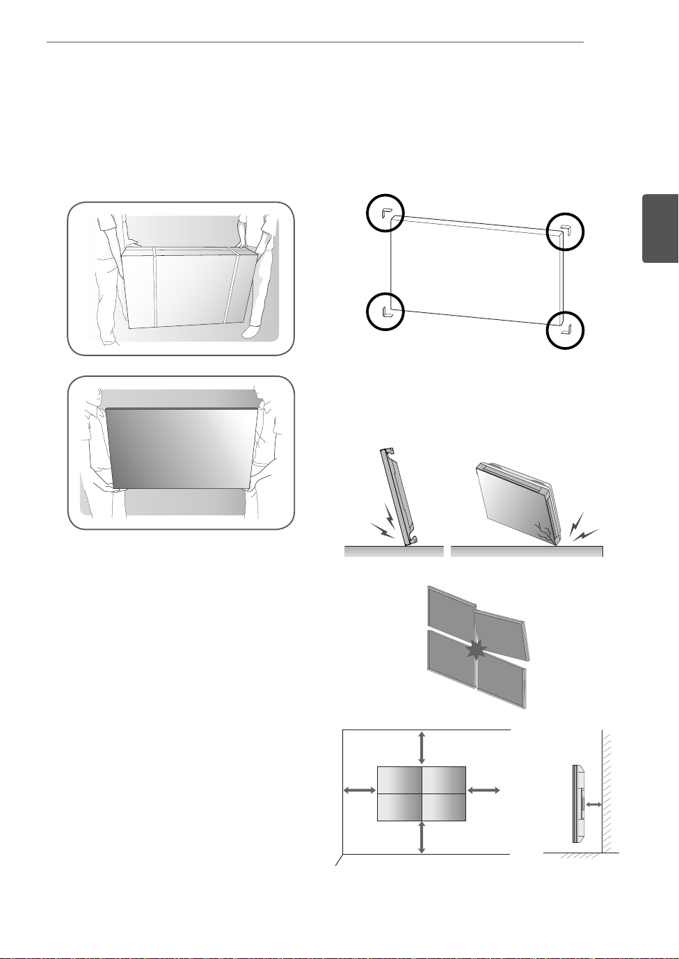
PRECAUTION IN HANDLING Precaution
Move the Set as a team of 2 persons. When you move
the bare Set, please use one hand on grabbing the
handle and the other support under the Set.
1 Remove the L-bracket on the corner of the Set be-
fore installation. When moving the Set, re-assemble
the L-bracket.
2 Be careful not to collide the sets with the floor or with
each other. Install in the space with enough airflow.
ENGLISH
ENG
10 cm
10 cm
20 cm
10 cm10 cm
ASSEMBLING AND PREPARING
6
ENGLISH
ENG
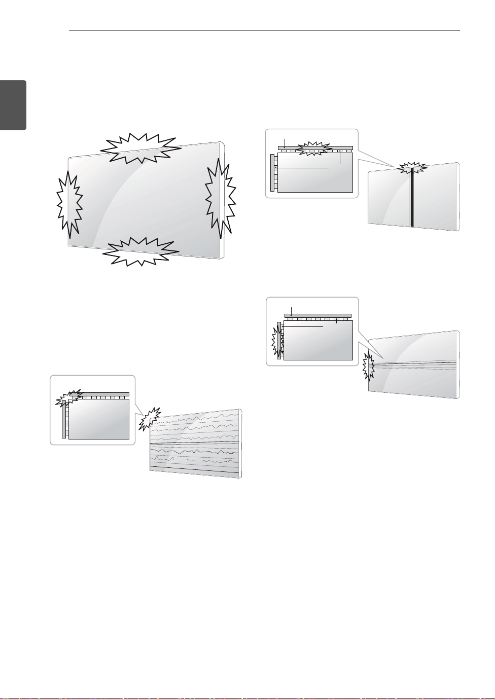
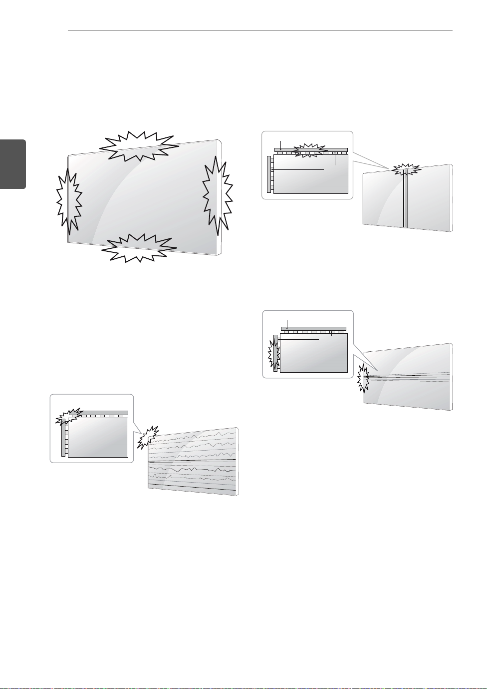
Causes & Phenomena of the
Line Defect
The line defect would occur on your Set if you strike on
the edge of the Set.
LOG (LINE ON GLASS) DEFECT
1 Shock on Module Left/Top Corner ➙ Left/Top LOG
Crack ➙ Horizontal Line Defect
COF (CHIP ON FILM) DEFECT
1 Shock on Module Top Side ➙ Top COF Crack ➙
Vertical Line Defect
Source PCB
COF Cable
2 Shock on Module Left Side ➙ Left COF Crack ➙
Horizontal Line Defect
Source PCB
COF Cable
ASSEMBLING AND PREPARING
7
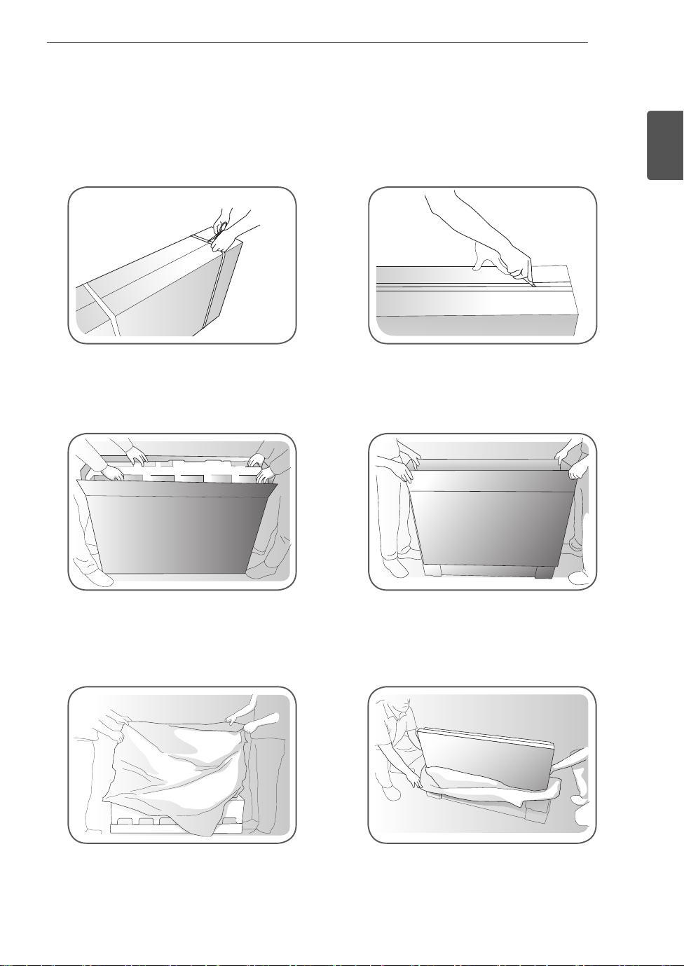
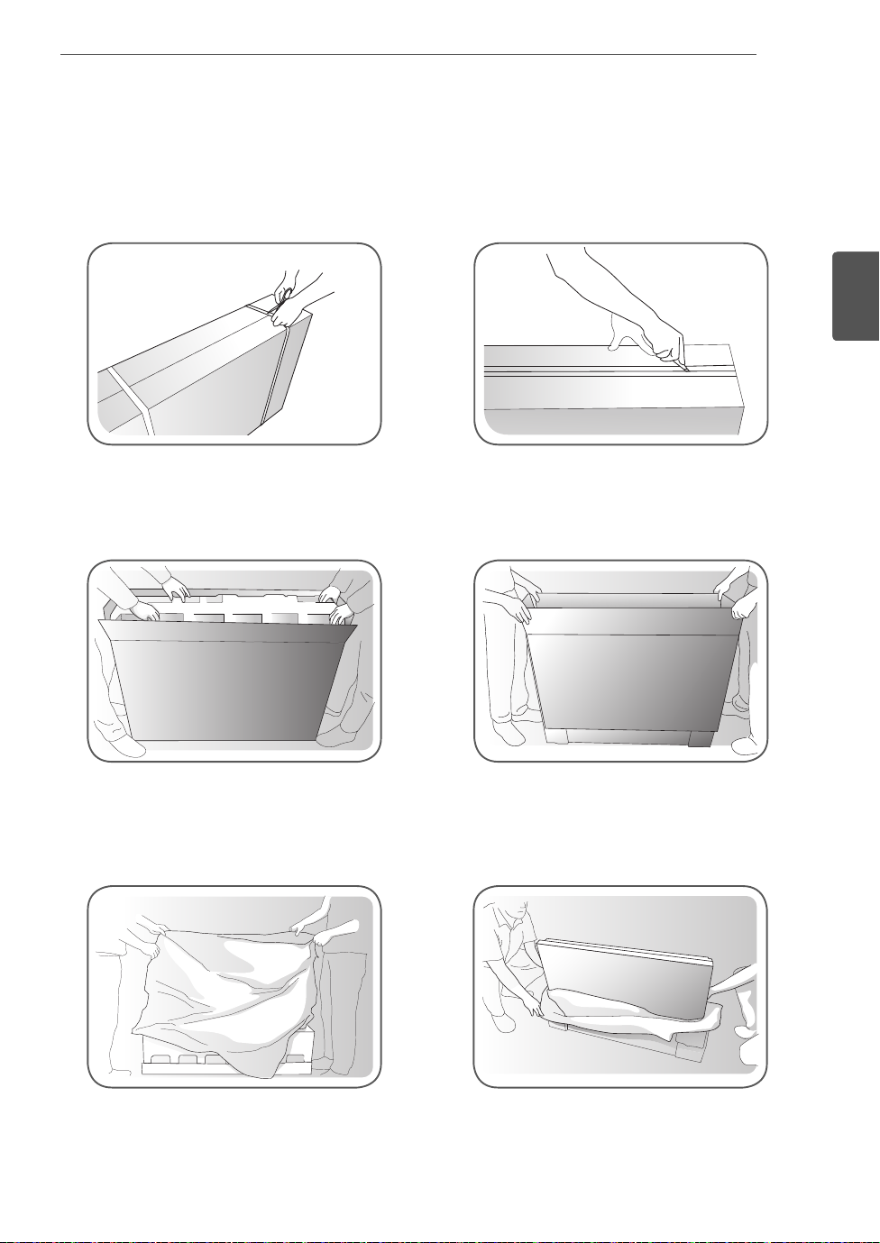
Installing the Product
- The illustration may look different from the actual product.
1 Cut Packing Strap of the Box.
3 Open the Box and remove the top packing.
2 Cut Tape on the Box.
4 Remove the Upper Box.
ENGLISH
ENG
5 Open the Poly Bag.
6 Undress the Poly Bag.
ASSEMBLING AND PREPARING
8
ENGLISH
ENG
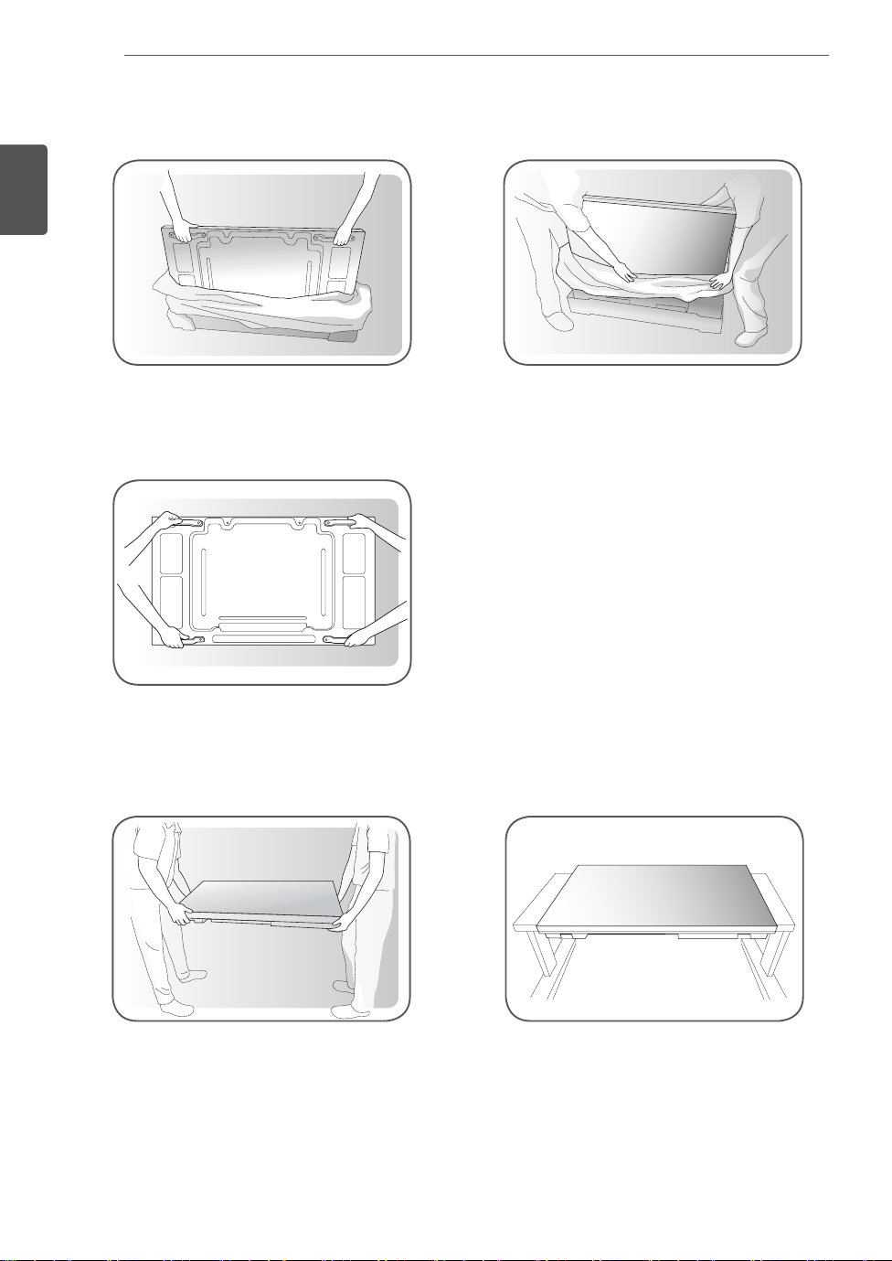
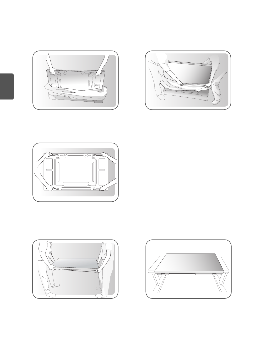
7 Lift up the Set using the SIDE/BACK Handle.
8 Remove Bottom packing when lifting up the Set.
9 With one hand under the set and the other hand grabbing the set, move the set.
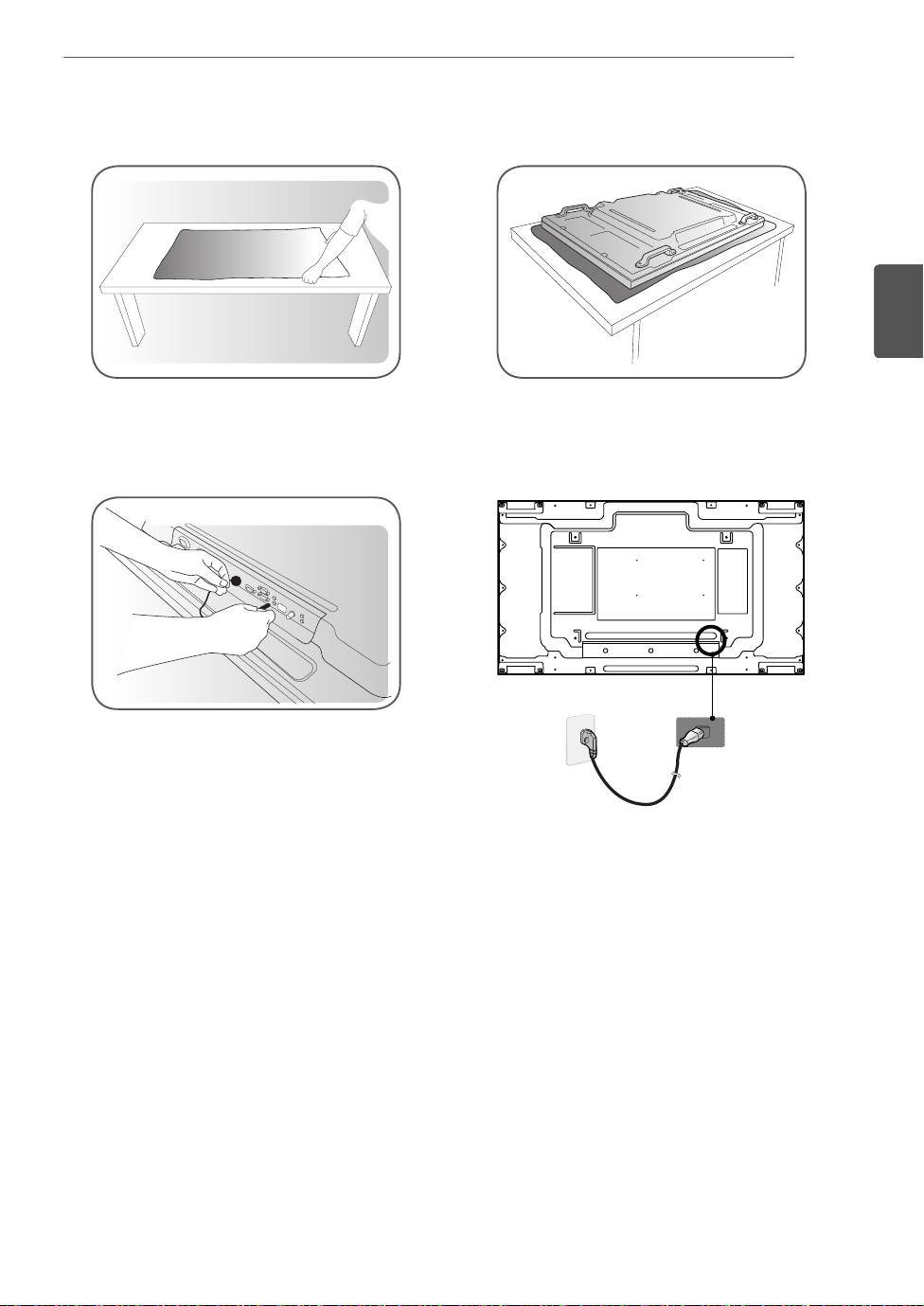
10 Lay the back of the Set down on the table.
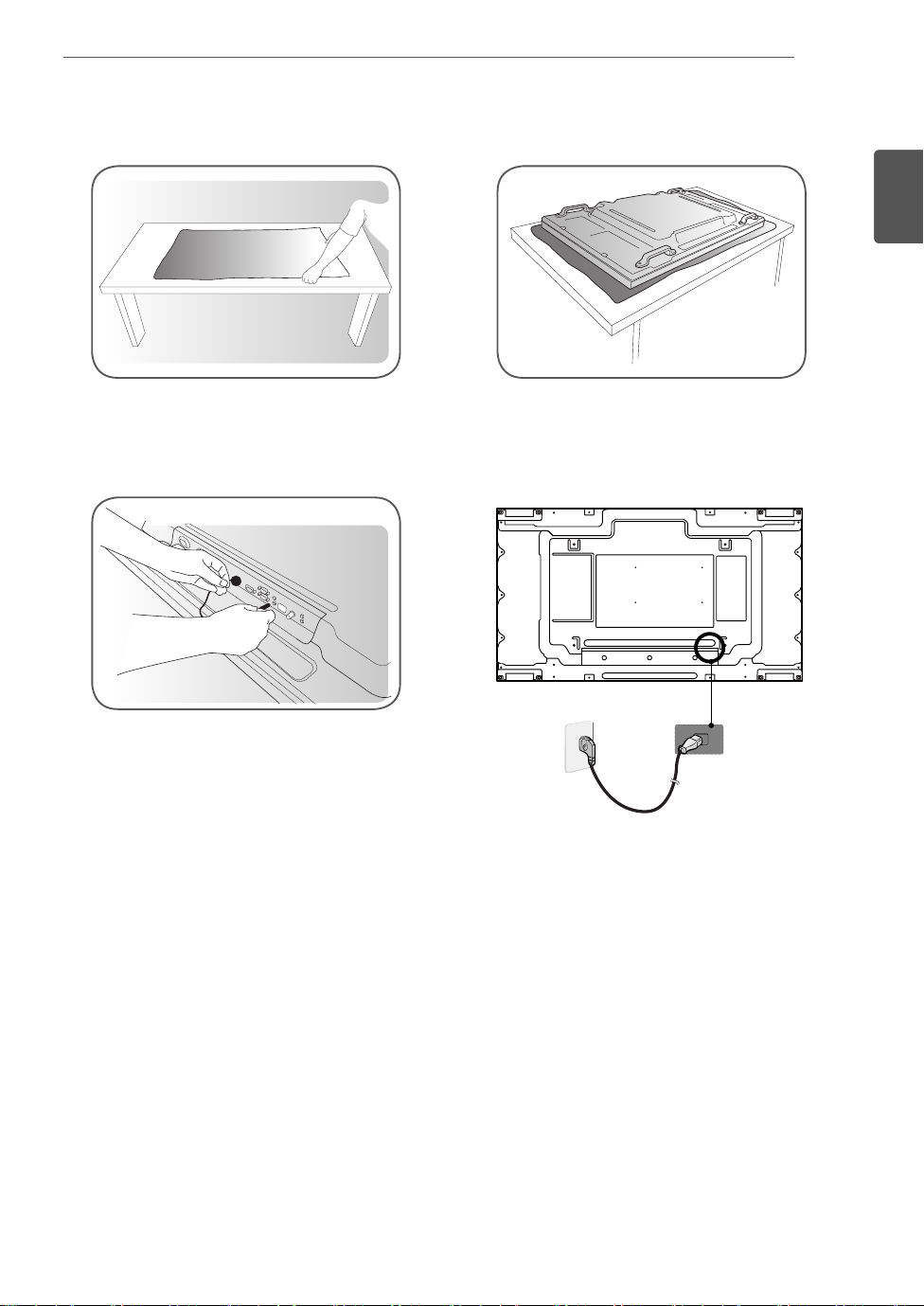
11 Use the cushion or Pad when you lay the face of the Set downward.
12 Connect IR receiver to use remocon. And then, connect power cord.
ASSEMBLING AND PREPARING
9
ENGLISH
ENG
2
1
ASSEMBLING AND PREPARING
10
ENGLISH
ENG
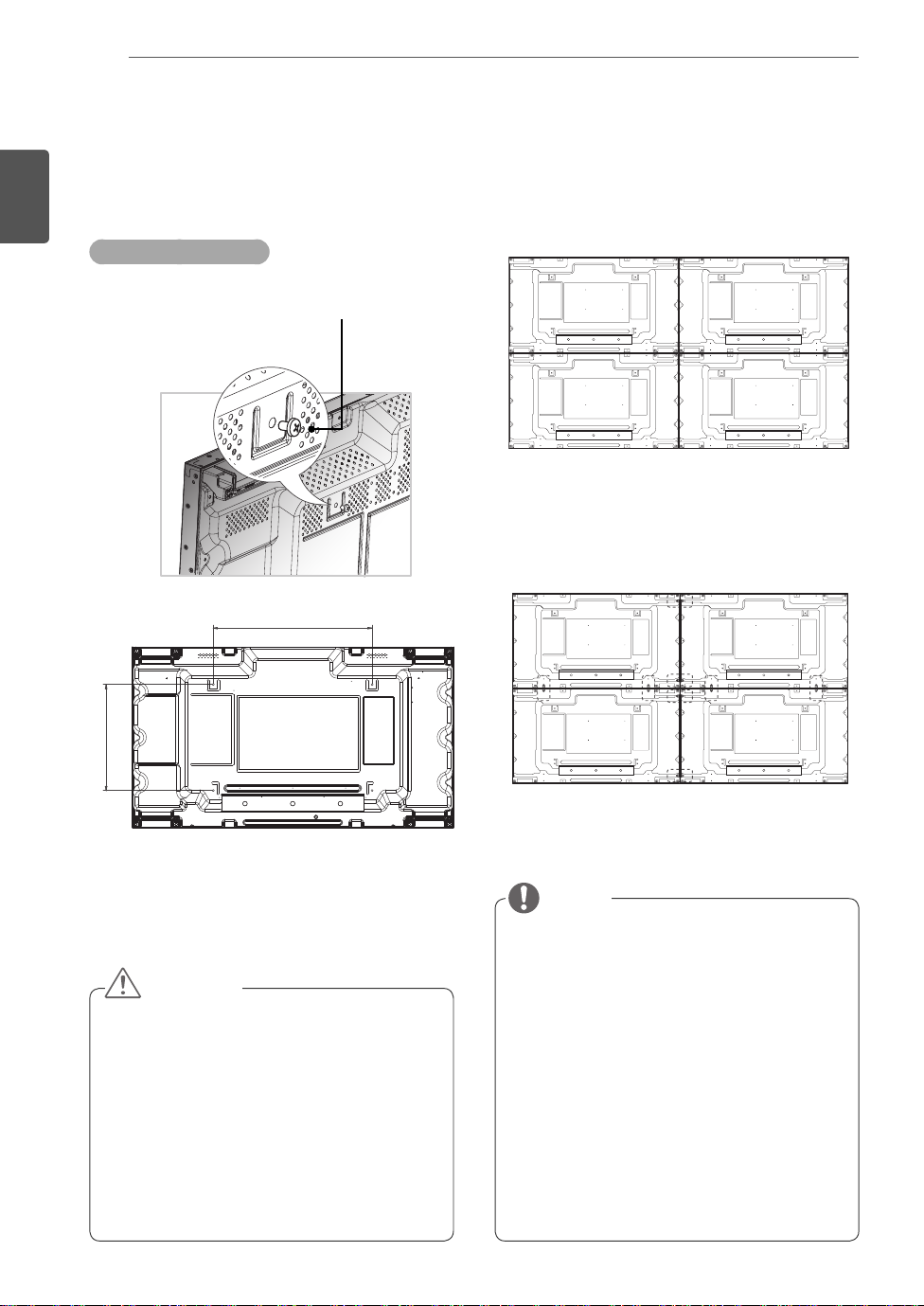
Tiling Displays
How to Mount the Set
Example of 2 x 2 tiling
Screws for attaching the
VESA wall mount (M6)
600
How to Join Sets
1 Join other sets using screws for fixing the
VESA wall mount in the same way as above.
Set 4 joined to the rest of the sets
(2 x 2 tiling)
2 After joining the sets, use the tiling guide to
adjust the gap between the sets.
400
CAUTION
When you connect Monitor sets for
multivision, you may find that the screen
color is not the same across all the Monitor
sets. If you want to adjust the screen color
manually, please refer to the Installation
Manual.
When you install multiple Monitor sets onto a
wall, attach the IR Receiver to all the sets, or
use an RS-232C cable to connect them and
then attach the IR Receiver to the first set.
3 Now the 2 x 2 tiling is complete. You can tile in
various combinations, such as 3 x 3.
NOTE
The load applied to each set should be
supported by the wall mount plate or the wall
using a VESA wall mount (600 x 400).
The load applied to each set should be
supported by the wall mount plate using a
VESA wall mount. (Each set must be firmly
mounted to the wall mount plate or the wall.)
You may mount the set without using
the tiling guide; this does not affect the
performance of the device.
Loosen the screws on the set to install the
tiling guides. (The screws are enclosed with
the other components in the box, including
the tiling guides.)
REMOTE CONTROL
11
REMOTE CONTROL
The descriptions in this manual are based on the buttons of the remote control. Please
read this manual carefully and use the Monitor set correctly.
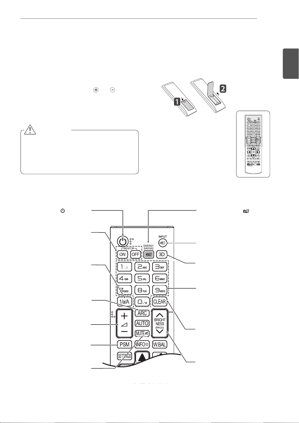
To replace batteries, open the battery cover, replace
batteries (1.5 V AAA) matching
label inside the compartment, and close the battery
cover. To remove the batteries, perform the installation
actions in reverse.
CAUTION
Do not mix old and new batteries, as this
may damage the remote control.
Make sure to point the remote control to the
remote control sensor on the monitor set.
(POWER)
Turns the monitor set on or off.
Turn on the monitor.
Turn off the monitor.
MONITOR ON
MONITOR OFF
and ends to the
ENERGY SAVING( )
Reduces power consumption
by adjusting peak screen
brightness.
INPUT
Selects the input mode.
ENGLISH
ENG
Toggles between numerical
1/a/A Button
and alphabetical.
ARC
Selects the Aspect Ratio
Mode.
Volume Up / Down
This button does not apply to
this model.
PSM
Selects the Picture Status
Mode.
MUTE
Mutes all sounds.
3D
This button does not apply to
this model.
Number and Alphabet Buttons
Enters numerical or alphabetical
characters depending on the
setting.
CLEAR
Deletes the entered numerical
or alphabetical character.
BRIGHTNESS Key
Adjust the brightness by
pressing the Up and Down
buttons on the remote control.
In USB mode, the OSD menu
has the Page function to move
to the next file list.
ENGLISH
ENG
REMOTE CONTROL
12
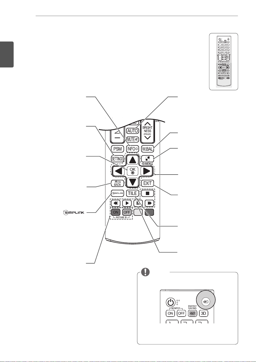
Displays the input
INFO
information.
SETTINGS
Accesses the main menus
or saves your input and exit
menus.
OK
Selects menus or options and
confirms your input.
BACK
Allows the user to move back
one step in user interaction
function.
Allows you to control various
multimedia devices simply
by using the remote control
through the SimpLink menu.
(It may not be supported
depending on the model.)
ⓘ
AUTO
Automatically adjusts picture
position and minimizes image
instability.(RGB input only)
W.BAL
Enters the White Balance
menu.
S.MENU
(SuperSign Menu Key)
This button does not apply to
this model.
Navigation Buttons
Scrolls through menus or
options.
EXIT
Clears all on-screen displays
and returns to Monitor set
viewing from any menu.
TILE
Selects the TILE Mode.
When the number of Picture
ID ON/OFF
ID is equal to Set ID you can
control the monitor which
you want in the multi display
condition.
USB Menu control buttons
Controls media playback.
NOTE
Select an input signal.
INPUT
AV ➙ Component ➙ RGB ➙ HDMI ➙ DVI-D ➙
Dispaly Port ➙ USB
MAKING CONNECTIONS
13
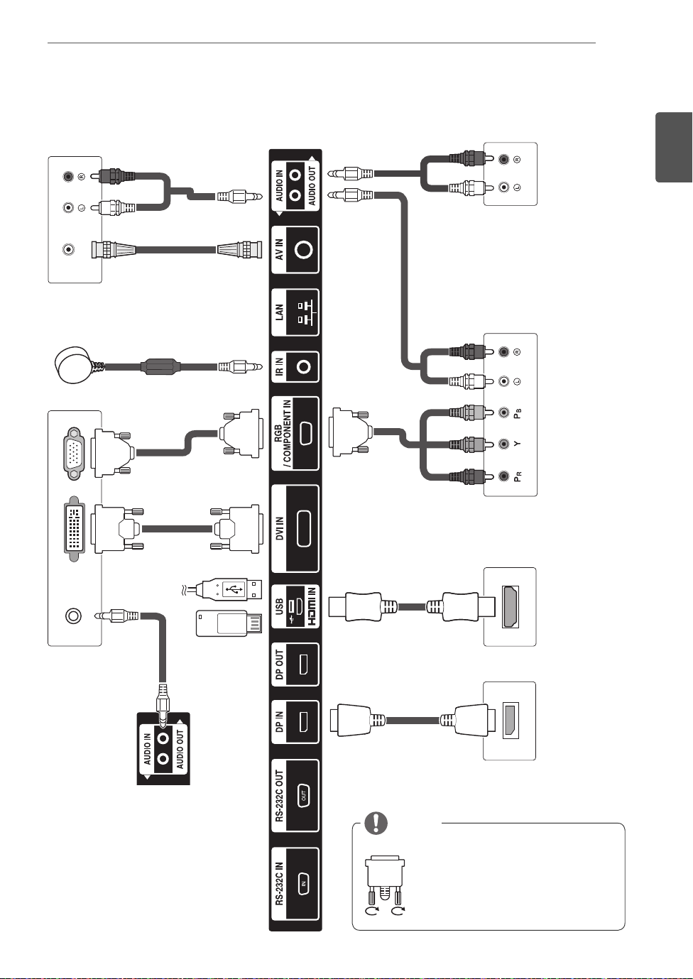
MAKING CONNECTIONS
VIDEO OUT
ENGLISH
ENG
AUDIO IN
NOTE
Connect the signal input cable
and tighten it by turning the
screws clockwise.

MAKING CONNECTIONS
14
ENGLISH
ENG
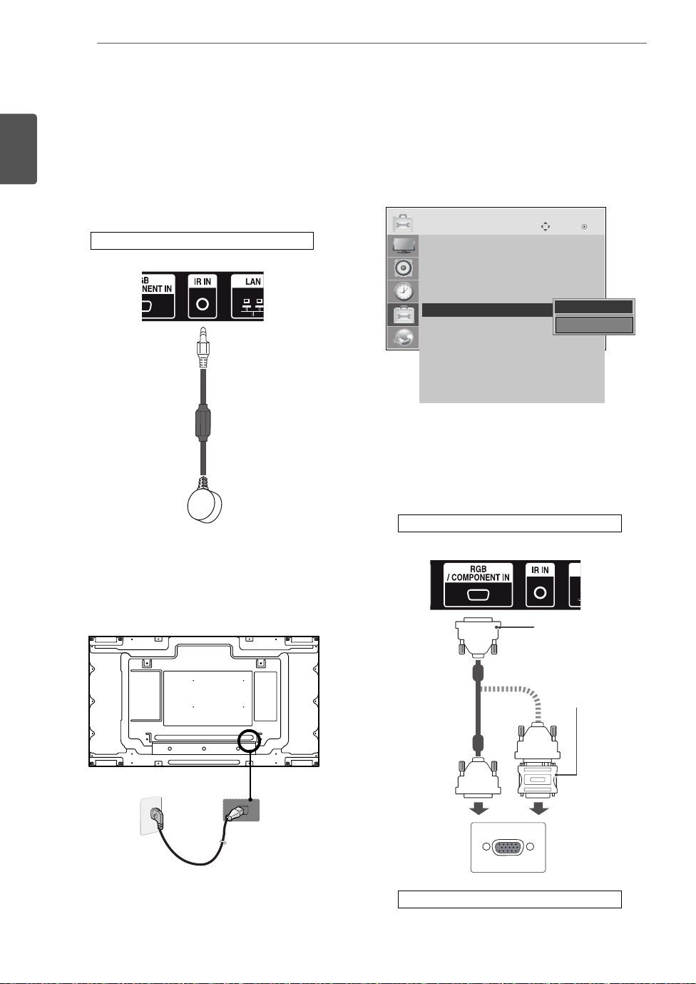
Connecting the Power Cord
Power Button
2
1
Connecting the External devices
HD Receiver DVD VCR
HDMI
DVI
AV
Component
Speaker
PC Camcorder/ Camera Gaming device
HDMI
DVI
RGB
LAN
Display Port
HDMI
DVI
AV
Component
HDMI
DVI
AV
Component
AV
Component
Memory storage
USB
HDMI
AV
Component
MAKING CONNECTIONS
15
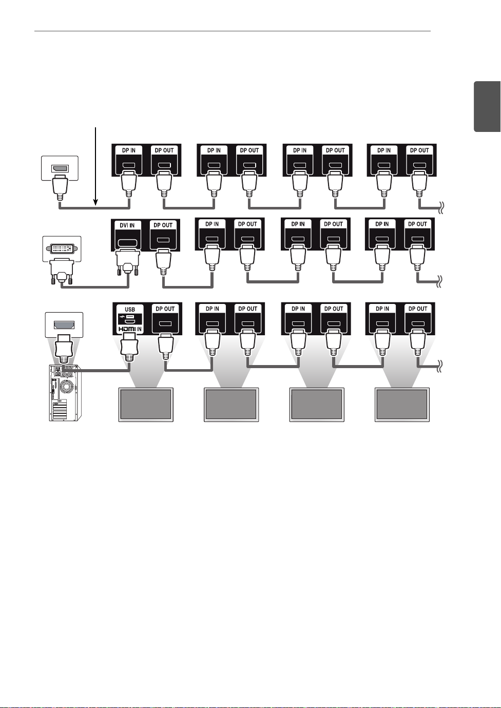
Daisy Chain Monitors
DP Cable
Use the cable provided with the product or use a DisplayPort certified cable version 1.1a or higher.
ENGLISH
ENG
Monitor 1 Monitor 2 Monitor 3 Monitor 4
MULTIVISION CONFIGURATION
16
ENGLISH
ENG
MULTIVISION CONFIGURATION
Set ID setup for each set. (* The model
Function Setting
IR Receiver connection.
1
Back of the product.
3
55LV75A does not support any functions for
controlling the Fan.)
OPTION
• Language
• ISM Method : Normal
• DPM Select : 5 sec.
• Fail Over : Off
• Factory Reset
• Set ID : 1
ꔋ
• Tile Mode
• PIP/PBP
• Fan
• USB Content Recovery : Off
• SIMPLINK
• Product/Service Info.
IR Receiver removal for all sets except for Set 1.
4
RGB connection.
5
Move OK
◀ 1 ▶
Close
Connecting the Power cord.
2
2
Back of the product.
15-pin D-Sub Signal
Cable (Max 3m)
(not included)
Macintosh Adapter
(not included)
1
PC/ MAC
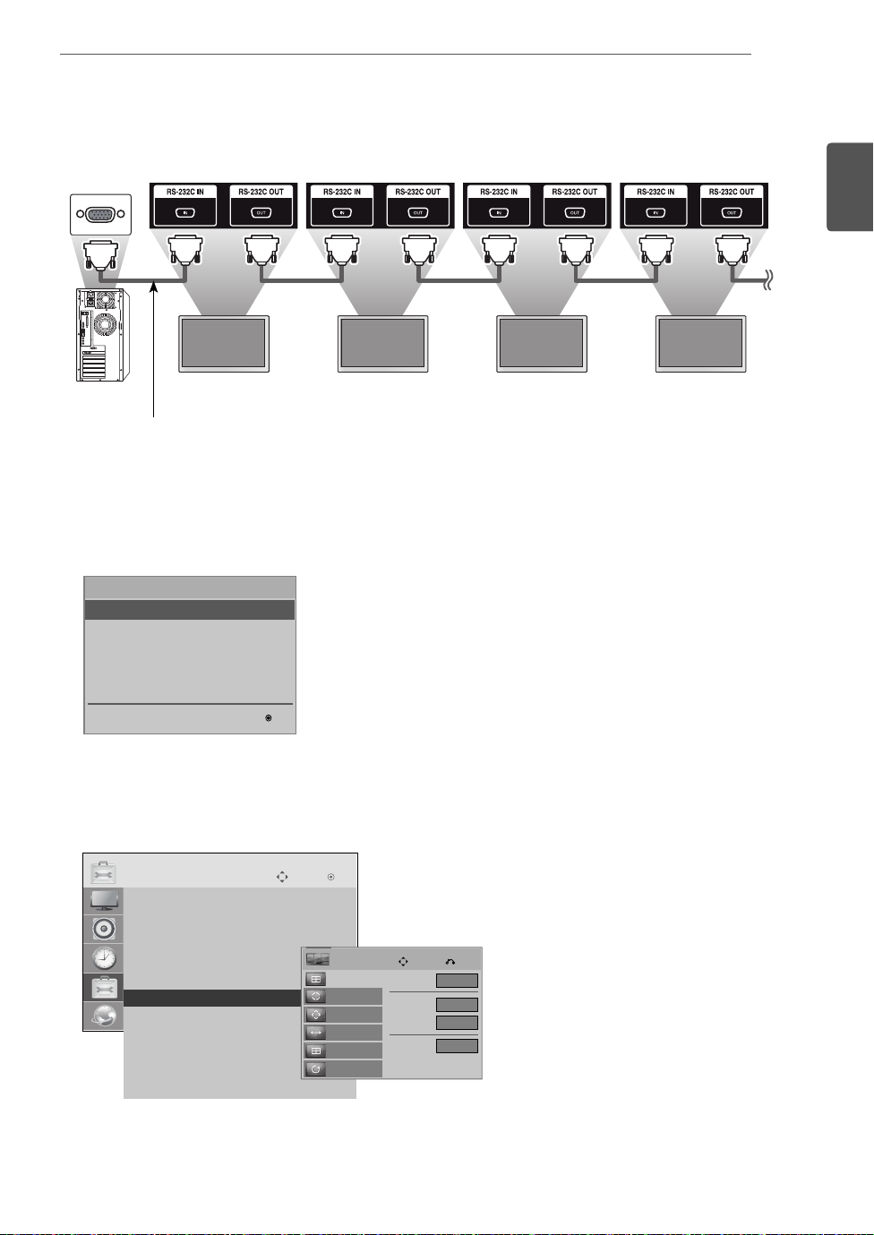
Connect the Monitor sets, in series, using an RS-232C cable.
T
6
Monitor 1 Monitor 2 Monitor 3 Monitor 4
RS-232C Cable
Installation Menu setup.
7
MULTIVISION CONFIGURATION
17
ENGLISH
ENG
Installation Menu (V 2.21)
LG Digital Signage Setup
White Balance Adjust
Password Change
Confi guration Cloning
Set ID Setup
OK
Tile Mode setup. (* The model 55LV75A does not support any functions for controlling the Fan.)
8
OPTION
• Language
• ISM Method : Normal
• DPM Select : 5 sec.
• Fail Over : Off
• Factory Reset
• Set ID : 1
ꔋ
• Tile Mode
• PIP/PBP
• Fan
• USB Content Recovery : Off
• SIMPLINK
• Product/Service Info.
Move OK
Tile
Tile Mode
Auto Config.
Position
Size
Natural
Reset
Move Prev.
Tile Mode
Row
Colunm
Tile ID
▶
◀
Off
2
2
1

ENGLISH
T
ENG
MULTIVISION CONFIGURATION
18
Setting the Tile Mode
In Tile Mode you can view an image in a larger
scale by connecting multiple monitors.
Tile Mode Off:
enlarged, and the same image is shown on
all connected monitors.
Tile Mode On:
according to the value in the H. Set Count
and V. Set Count fields.
(* The model 55LV75A does not support any
functions for controlling the Fan.)
An input image is not
An input image is enlarged
1X2
When using 2 monitors
ID 2ID 2
ID 1ID 1
Tile ID
2X2
When using 4 monitors
ID 2ID 2
ID 1ID 1
OPTION
• Language
• ISM Method : Normal
• DPM Select : 5 sec.
• Fail Over : Off
• Factory Reset
• Set ID : 1
ꔋ
• Tile Mode
• PIP/PBP
• Fan
• USB Content Recovery : Off
• SIMPLINK
• Product/Service Info.
Move OK
Tile
Tile Mode
Auto Config.
Position
Size
Natural
Reset
Move Prev.
Tile Mode
Row
Colunm
Tile ID
ID 4ID 4
ID 3ID 3
3X3
◀
Off
2
2
1
▶
When using 9 monitors
ID 1ID 1
ID 4ID 4
ID 7ID 7
ID 2ID 2
ID 5ID 5
ID 8ID 8
ID 3ID 3
ID 6ID 6
ID 9ID 9
4X4
When using 16 monitors
ID 1ID 1
ID 5ID 5
ID 9ID 9
ID 13ID 13
ID 2ID 2
ID 6ID 6
ID 10ID 10
ID 14ID 14
ID 3ID 3
ID 7ID 7
ID 11ID 11
ID 15ID 15
ID 4ID 4
ID 8ID 8
ID 12ID 12
ID 16ID 16
MULTIVISION CONFIGURATION
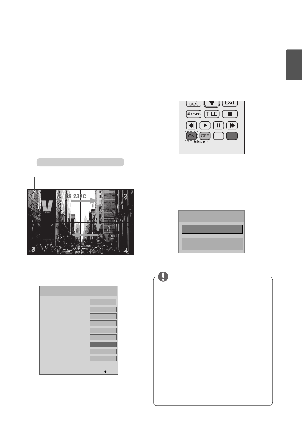
Setting the Picture ID
The Picture ID menu allows you to control all sets using the IR Receiver connected to Set 1.
The IR signal of the remote control is
transmitted through the RS-232C cables
connected in serial mode.
When you set a Picture ID using the remote
control, you can only control the Set that
matches the Picture ID.
ex) For example, if you set a Picture ID to 2,
you can only control the monitor with the
Set ID 2.
If Picture ID is set to Off, you can control all
monitors at the same time.
2X2 Multi-Vision (Total Set ID: 4)
IR Receiver
Press the red ON button on the remote control
2
to assign the Picture ID.
If you press the left/right buttons or press the
3
ON button repeatedly, the Picture ID cycles
through OFF/1 and the value set in the Total Set
ID.
19
ENGLISH
ENG
Set the Total Set ID in the Installation Menu.
1
LG Digital Signage Setup (V2.21)
• Factory Reset
• Menu Display
• OSD Display
• LG IR Operation
• Local Key Operation
• Input Source Change
• Total Set ID
• Baudrate
• Min Volume
Sets the total number of products to be connected in
Tile mode. Total Set ID is used as the maximum value of
Picture ID.
▲
▼
◄
Off
On
On
On
On
On
255
9600
0
►
OK
Picture ID
◄ Off ►
Close
NOTE
For example, if the Picture ID is assigned to
2, the upper right display (Set ID: 2) can be
controlled by IR signals.
For each set, you can change the settings
for the PICTURE, AUDIO, TIME, NETWORK
and MY MEDIA menus or the hot keys on the
remote control.
If you press the green OFF button for Picture
IDs, the Picture IDs for all sets are turned off.
If you then press any button on the remote
control, all sets will start working again.
Picture ID will be disabled while using the
MY MEDIA menu.
If Picture ID is set to Off, holding buttons
on the remote control will execute only one
action at a time.


Easy Setup Guide
Digitální monitor LG pro
ČESKY
reklamní panely
(MONITOR PRO REKLAMNÍ PANELY)
Před uvedením zařízení do provozu si pečlivě prostudujte tento návod auložte jej pro budoucí potřebu.
55LV75A
55LV77A
www.lg.com
ČESKY
CS
MONTÁŽ A PŘÍPRAVA
2
MONTÁŽ A PŘÍPRAVA
Vybalení
Zkontrolujte, zda produkt obsahuje následující položky. Pokud některé příslušenství chybí, obraťte se na
místního prodejce, od něhož jste produkt zakoupili. Vyobrazení v tomto návodu se může lišit od skutečného
produktu nebo příslušenství.
CD (návod k obsluze) /
karta
Dálkový ovladač
a baterie
Napájecí kabel Kabel RS-232CPřijímač IR
Kabel DP
Šroub M4 x L6
(8ea)
Šroub M6 x L10
(4ea)
Průvodce pro
vertikální stěnu
(4ea)
Kabelová spojka pro
montáž (2ea)
UPOZORNĚNÍ
Nepoužívejte jiné než schválené položky, jinak není zaručena bezpečnost a životnost produktu.
Záruka se nevztahuje na poškození a zranění způsobená neschválenými položkami.
POZNÁMKA
Příslušenství dodané se zařízením se může v závislosti na modelu lišit.
Specifikace výrobku nebo obsah v tomto návodu se mohou za účelem zlepšení funkcí výrobku změ-
nit bez předchozího upozornění.
Software SuperSign a příručka
- Stahování z webu společnosti LG Electronics.
- Navštivte webovou stránku společnosti LG Electronics (
a stáhněte si nejnovější software pro svůj model.
http://www.lgecommercial.com/supersign
)

Rozměry (šířka × výška × hloubka) / hmotnost
v
MONTÁŽ A PŘÍPRAVA
3
š
1213,4 mm x 684,2 mm x 88,5 mm / 23 kg
h
Zobrazení návodu k obsluze
Vložte disk CD-ROM do počítače.
Disk CD-ROM se otevře automaticky. (pouze v systému Window).
Pokud se automaticky nespustí, zobrazí se níže uvedená sekvence.
Můj počítač ➙ Digital_LG(CD-ROM) ➙ Otevřít Index.htm
Můj počítač ➙ Digital_LG(CD-ROM) ➙ Návod ➙ Otevřít návod k obsluze
ČESKY
CS
MONTÁŽ A PŘÍPRAVA
4
Bezpečnostní opatření při přenášení
- Vyobrazení v tomto návodu se mohou lišit od skutečného výrobku nebo položky.
ČESKY
CS
Dodržujte varovné značky vyobrazené na balení.
Nepoužívejte upínací zařízení.
Zabraňte pádu z upínacího zařízení.
Přenášení vyžaduje 2 osoby.
Nakládejte opatrně.
Zabraňte pádu, jsou-li balení
naskládána na sobě.
Přenášení vyžaduje 4 osoby.
Nepřepravujte ve vodorovné poloze.
Zabraňte převrácení monitoru.
Nepokládejte produkt na krabici.
Vyvarujte se upuštění.
Touto stranou nahoru/ Křehké/ Nevystavujte dešti/
Max. 4 balení na sobě
O produkt se neopírejte.
MONTÁŽ A PŘÍPRAVA
5
Bezpečnostní opatření při
manipulaci
Monitor by měly společně přenášet 2 osoby. Při přenosu
vybaleného monitoru jednou rukou uchopte držadlo a
druhou monitor zajistěte zespodu.
Bezpečnostní opatření
1 Před instalací odstraňte L-lišty z každého rohu
monitoru. Při přenášení monitoru, L-lišty znovu
připevněte.
ČESKY
CS
2 Dejte pozor, aby nedošlo k pádu monitorů na
zem nebo k jejich srážce. Nainstalujte v prostoru
s dostatečným prouděním vzduchu.
10 cm
10 cm
20 cm
10 cm10 cm
MONTÁŽ A PŘÍPRAVA
6
ČESKY
CS
Vady řádku a jejich příčiny
K vadám řádku může dojít v důsledku nárazu do hrany
monitoru.
VADA MODULU LOG (LINE ON GLASS)
1 Náraz do modulu v levém horním rohu ➙ poškození
modulu LOG vlevo nahoře ➙ vada vodorovného
řádku.
VADA MODULU COF (CHIP ON FILM)
1 Náraz do modulu na horní straně ➙ poškození
horního modulu COF
Source PCB
➙ vada svislého řádku.
COF Cable
2 Náraz do modulu na levé straně ➙ poškození
modulu COF na levé straně ➙ vada vodorovného
řádku.
Source PCB
COF Cable
Instalace produktu
- Vyobrazení v tomto návodu se mohou lišit od skutečného výrobku nebo položky.
MONTÁŽ A PŘÍPRAVA
7
1 Odstraňte balicí pásku.
3 Otevřete balení a odstraňte horní část obalu.
2 Přeřízněte lepicí pásku na balení.
ČESKY
CS
4 Odstraňte vnější část balení.
5 Otevřete plastikový obal.
6 Sejměte plastikový obal.
MONTÁŽ A PŘÍPRAVA
8
ČESKY
CS
7 Zdvihněte monitor pomocí držadel NA BOKU/ZADNÍ
STRANĚ.
8 Při zdvihnutí monitoru odstraňte spodní část obalu.
9 Při přenášení monitoru umístěte jednu ruku pod monitor a druhou jej uchopte.
10 Položte monitor zadní stranou dolů na stůl.
11 Pokud pokládáte monitor obrazovkou dolů, použijte podložku.
12 Chcete-li používat dálkový ovladač, připojte přijímač IR. Poté připojte napájecí kabel.
MONTÁŽ A PŘÍPRAVA
9
ČESKY
CS
2
1

MONTÁŽ A PŘÍPRAVA
10
ČESKY
CS
Stěna z monitorů
Jak upevnit monitor
*Příklad stěny 2 x 2
Šrouby pro upevnění držáku
na stěnu VESA (M6)
600
Propojení monitorů
1 Připojte ostatní monitory pomocí šroubů pro upevnění
držáku na stěnu VESA stejným způsobem, jaký je
popsaný výše.
Monitor 4 spojený s ostatními monitory
(stěna 2 x 2)
2 Po připojení monitorů použijte průvodce pro montáž
na stěnu, abyste nastavili mezeru mezi monitory.
400
UPOZORNĚNÍ
Pokud připojíte více monitorů pro vícenásob-
né zobrazení, nemusí mít obrazovky monitorů stejnou barvu na všech monitorech. Pokud
chcete ručně přizpůsobit barvu obrazovky,
více informací naleznete v instalační příručce.
Při instalaci více monitorů na zeď připevněte
ke všem monitorům přijímač IR nebo pro
připojení použijte kabel RS-232C a přijímač
IR připevněte k prvnímu monitoru.
3 Nyní je montáž stěny 2 x 2 dokončena.
Monitory můžete spojovat i v jiných kombinacích,
například 3 x 3.
POZNÁMKA
Váha jednotlivých monitorů by měla být nese-
na deskou pro montáž na stěnu nebo stěnou
za použití montážní desky VESA (600 × 400).
Váha jednotlivých monitorů by měla být ne-
sena deskou pro montáž na stěnu za použití
montážní desky VESA. (Každý monitor musí
být pevně připevněn k desce pro montáž na
stěnu nebo ke stěně.)
Monitory lze rovněž připevnit bez použití prů-
vodce pro montáž na stěnu; nedojde k ovlivnění výkonu zařízení.
Uvolněním šroubů na monitoru nainstaluje-
te lišty pro montáž na stěnu. (Šrouby a ostatní součásti, včetně lišt pro montáž na stěnu,
jsou součástí balení.)
 Loading...